
InspectAPedia® FREE Encyclopedia of Building & Environmental Construction, Diagnosis, Maintenance & Repair |
Question? Just ask us! InspectAPedia
|
 Electrical Receptacle Wire Connections
How to wire up an electrical plug outlet or wall receptacle / plug
- POST a QUESTION or COMMENT about how to install and wire electrical outlets or receptacles in buildings.
How to wire up an electrical receptacle:
Here we illustrate basic connections seen in the field for the black, white neutral or grounded conductor), and ground wire when hooking up an electrical receptacle (wall plug or "outlet").
We describe how to wire an electrical receptacle by making the right connections between individual electrical wires and the proper screw or clamp connectors on the electrical receptacle device itself.
We also describe connecting the ground wire between the circuit grounding conductor, receptacle ground screw, and the electrical box (if metal boxes are used).
Watch out: mis-wired electrical receptacles are dangerous. Electrical wiring should be performed by a licensed, trained electrician and should comply with the National Electrical Code and local regulations. This article series describes how to choose, locate, and wire an electrical receptacle in a home.
InspectAPedia tolerates no conflicts of interest. We have no relationship with advertisers, products, or services discussed at this website.
Electrical Wiring Connections for Installing an Electrical Receptacle
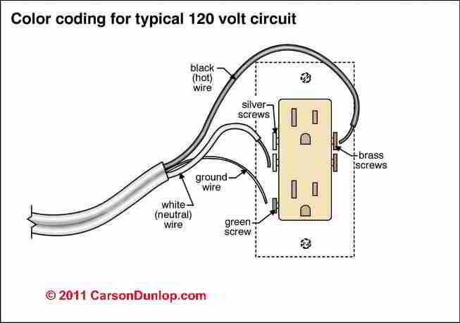
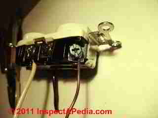
The illustration shows the typical wiring of an electrical outlet or "receptacle", courtesy of Carson Dunlop Associates.
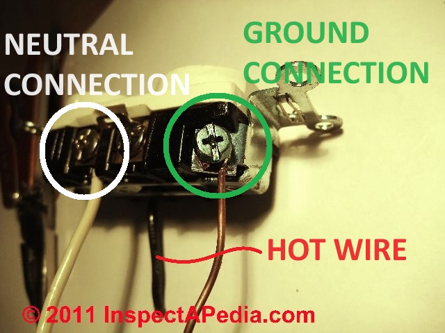
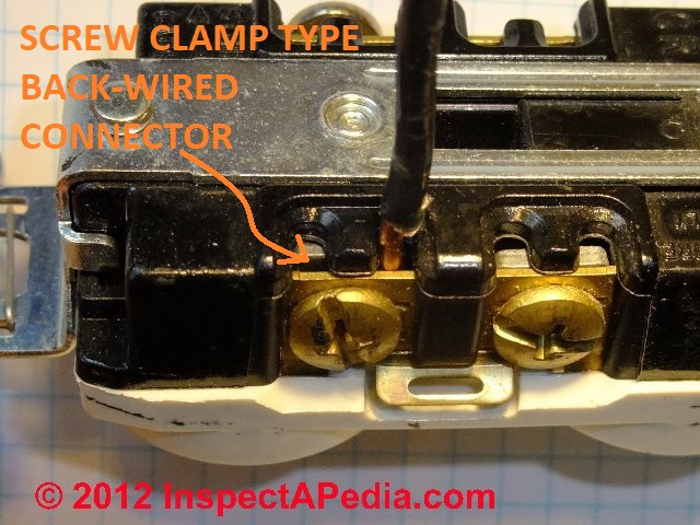
Our photo at page top is not an example of a proper electrical outlet installation.
Watch out: Electrical components in a building can easily cause an electrical shock, burn, or even death.
Even when a hot line switch is off, one terminal on the switch is still connected to the power source.
Before doing any work on the switch,
the power source must be turned off by setting a circuit breaker to OFF or removing a fuse.
Where do the Black, White, & Bare Ground Wires Go on an Electrical "Outlet" or Receptacle?
So where do the wires go: to which screws on the electrical receptacle (shown just above) do we connect the black wire, white wire, and ground wire? And what if there is no ground wire?
On a conventional 120-volt "two pronged" electrical outlet that accepts grounded plugs (two prongs plus the rounded center ground connector prong), your circuit will have three wires:
- The white "neutral" wire -
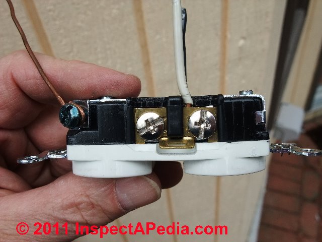
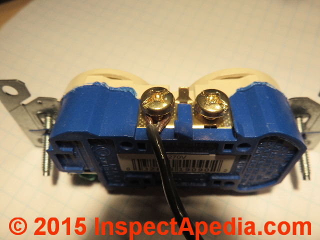
this wire is connected to the silver screw on the electrical receptacle, often labeled "neutral" or "white". You can see our white neutral wire connected to a silver screw on the receptacle in our photo.
- The black "hot" wire -
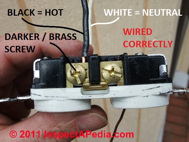
this wire is fed from the circuit breaker to deliver power to the receptacle, and it connects to the brass or bronze-colored screw on the receptacle, often labeled "hot" or "live" or "black" (or "red" in some situations).
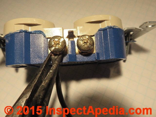
You will see the hot black wire connected to the bronze or darker-colored screw on the receptacle shown at below right. The receptacle we used for these photos happens to be a 20-A rated device that permits the wire to be inserted straight into a clamp that is tightened against the wire by the screw.
Watch out: for the safest, most reliable electrical connections use either the screw clamp connector shown here, or use a wire connected directly to a binding head screw. We don't recommend using the push-in type backwire method that relies on a simple spring-clip connector inside the device.
See BACKWIRED ELECTRICAL RECEPTACLES for details.
- The bare ground wire -
this wire connects to the green ground screw usually found on the bottom of the electrical receptacle (photo at left). You can also see our ground wire connected at the left side of our previous photo, above-left.
What if there are No Screws Indicating Hot & Neutral or What if Boths Sides Look the Same?
Wiring Rule for electrical receptaclrs: Connect the black wire to the brass colored screw, connect the white wire to the silver colored screw.
Watch out: But what if there are no screws or what if the screws look alike? Some older back-wire-only electrical receptacles or switches don't have any side terminal screws. And some new but dirt-cheap receptacles and switches have wire terminal screws that look exactly the same - at least in dim light.
In that case you don't have a screw color to give a clue about which is the neutral and which the hot wire connector.
All such electrical devices should sport a marking on their front or back telling you which terminals or which side of the device wires connect to HOT / BLACK and which side connects to the NEUTRAL / WHITE wires.
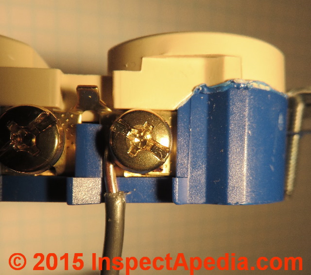
Below: here is a close-up photo of the front of this electrical receptacle. My red oval shows the location of a marking indicating WHITE on the face of the receptacle.
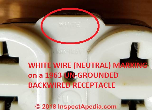
That tells the electrician which pair of the back-wire terminals to use for connecting the neutral wire - particularly important because as you'll see in my photo below, this 1963-vintage un-grounded 15A electrical receptacle did not sport screw terminals whose brass or silver color might otherwise have given us a wiring clue.
Reader Question: When wiring an electrical receptacle, what do I do with the red wire? Can I ground it?
I have a 3 wire (Black, White, Red and ground) feeding a outlet and I want to add another receptacle to run further down the line.
The line out is 14/2.
What do I do with the Hot Red wire? Can i attach it to the ground. - Rick
Reply: NO!!
Rick:
NEVER connect a hot (red or black) wire to ground (nor to the white neutral wire) - doing so would form a dead short, should trip a breaker, or if not, could cause a fire or could cause a dangerous shock.
If there is a hot wire that is not used in a junction box, SOP would be to cap it off with a twist-on connector.
It sounds as if you'd be best served by hiring a licensed electrician.
Reader follow-up:
After capping off the red wire, can I extend the line to the next plug by following the diagram above and adding the black and white wires to the respective second screw connections?
You see, the wiring has already been installed by the builders and they left the boxes without receptacles so all I have to do is connect them to the. I don't know why the extra red wire is there. It was done over a year ago. I want to finish the connections. It runs 14/3 and then 14/2. That's why I have the extra red.
Reply: how three-wire circuits or multiwire branch circuits with a common neutral (and ground) are used and wired
Rick often electricians run a 3-wire system into a building area using two hot wires and a shared neutral, to permit providing two circuits in an area while having to pull just one wire to the area. But to sort out how your wires were connected and are being used requires some expertise, visual inspection, and testing using a VOM.
Take a look at multi-wire branch circuit wiring information and hook-up details at MULTI-WIRE CIRCUITS.
What's the difference between "line" and "load" terminal screws on electrical receptacles?
Reader Question: What are the "Line" and "Load" marks on recetpacles and switches and which wires go to "LINE" and which wires connect to "LOAD" terminals?
What is the difference between the load and line terminal screws on a 15 or a 20 amp receptacle? How do i wire 4 more recepticles to an existing receptacle in a room? - Anon
Reply: how to wire line and load terminals on receptacles (outlets)
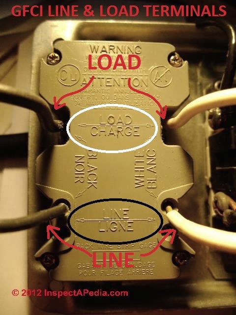
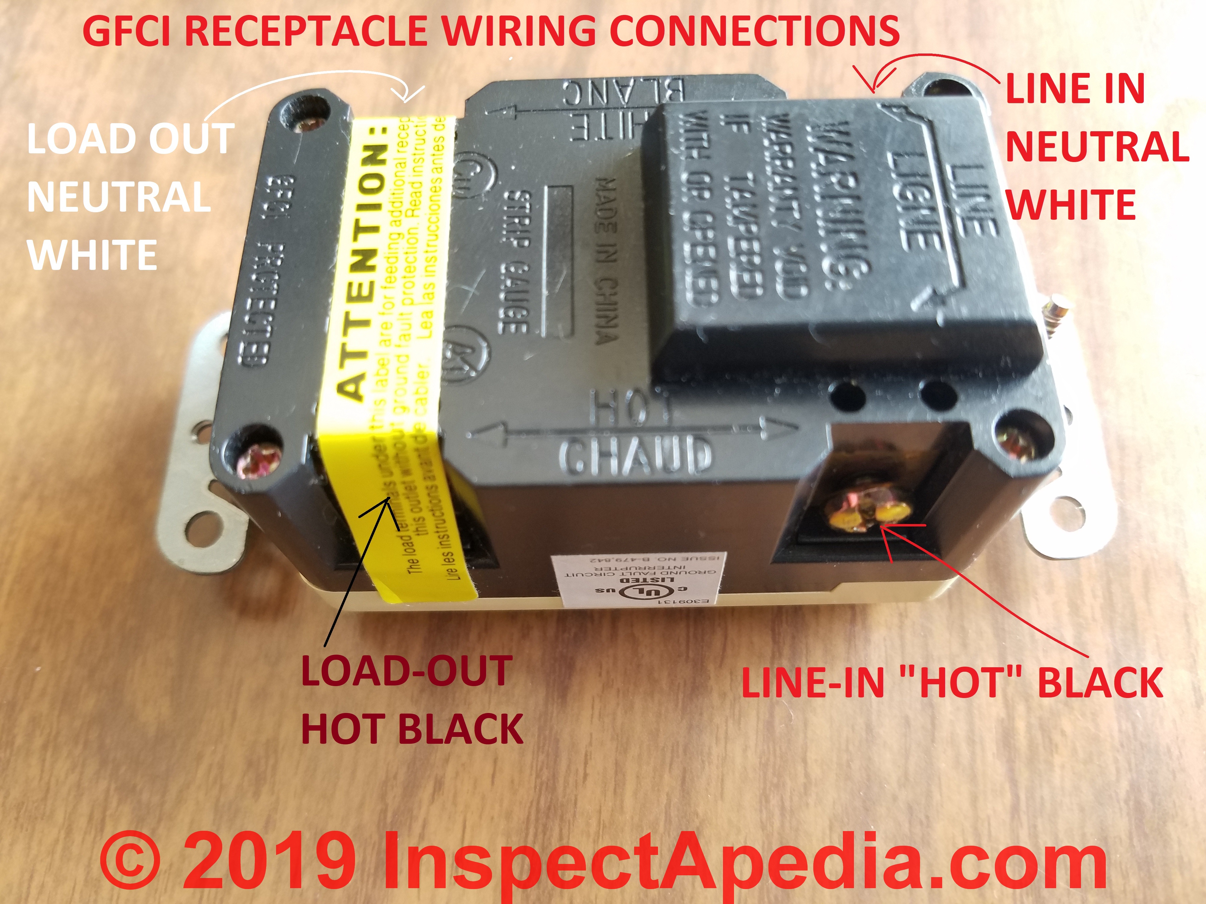
Anon: the line and load electrical wire connections are important to get right on certain electrical devices such as GFCIs and AFCIs. Our photograph (left) illustrates the line and load markings on the back of a GFCI electrical receptacle.
Looking at the side or back of the molded case of this and other electrical devices such as AFCIs, you will see that one pair of terminals will be marked "line" and the other "load".
Which wires connect to the "Line" terminals:
The Line terminals (green arrows in photo at left) on an electrical receptacle are for the incoming hot wire - the terminal marked LINE is connected to the incoming power source or the "hot" wire (typically black or red in insulation color) that connects to the brass colored screw (marked "Black" or "Noir) at the lower left " in our photo.
And the incoming neutral (white) wire from the electrical panel connects to the "Line" and "White" or "Blanc" terminal marked at the lower right in our photo
Which wires connect to the "Load" terminals"
The Load terminals (red arrows near the top of our photo at left) on an electrical receptacle are for the outgoing wires. These wires feed electrical receptacles that are located "downstream"(farther from the electrical panel) from the device. The outgoing hot or black wire (red arrow, above left in our photo) connects to the terminal marked "Load" or "Charge" and "Black" or "Noir".
The outgoing white, neutral wire, connects to the terminal marked "Load" or "Charge" and "White" or "Blanc" in our photograph.
Re-stating, terminals marked LOAD on a GFCI or AFCI are intended to be used to feed other devices (such as receptacle) that are wired "downstream" from the one being worked-on. In a string of electrical receptacles wired in series, incoming electrical power flows in to the first GFCI/AFCI receptacle and is connected to the LINE terminal.
The LOAD terminals of that device are connected to hot and neutral wires that subsequently are connected to the next electrical receptacle in the series.
To hook up a quad of electrical receptacles you'll need a larger junction box.
And often we wire two separate electrical circuits to the box, placing one pair of receptacles on one circuit and the other on the second circuit - that approach allows us to plug more devices into the wall at that location with less chance of overloading a single electrical circuit in the building.
Watch out: while a conventional receptacle may work with the line and load terminals reversed, a GFCI or AFCI will be unsafe if wired with that mistake, and those devices will not work properly nor test properly in all circumstances.
For example, if you connect the incoming "hot" wire and neutral wire to the "load" terminals on a GFCI, and if you connect wires leading to downstream electrical receptacles to the "line" terminals (these are the incorrect connections), then pushing the test button on the GFCI will not activate that device's internal trip mechanism.
Question: are receptacles wired "downstream", that is, after a GFCI receptacle OK?
Are receptacles wired after GFI receptacles OK? - Denny 11/25/12
Reply:
Denney,
Yes, and if wired correctly the downstream receptacles will also be GFCI protected.
Watch out: When wiring a GFCI the incoming leads are connected to the LINE terminals and the downstream receptacles are connected to the LOAD terminals marked on the back of the receptacle. If the devices is not wired correctly it is unsafe and does not provide the intended safety protection from ground faults.
How to Actually Connect the Wires at a Receptacle or Switch
[Click to enlarge any image]
There are two approaches to physically connecting electrical wires to an electrical receptacle ("Outlet") or to an electrical switch ("light switch" or "wall switch"). Back-wiring means connecting the wire through an opening or into a clamp accessed on the back of the receptalce or switch.
Our photo above illustrates using a screw-clamp back-wire connector on an electrical receptacle.
Alternatively a wire may be connected directly to a screw on the receptacle or switch as we show in the photo below.
Most literature refers to these as "binding head" screws or "binding head screw connector" because the head of the screw on modern receptacles and switches is designed to grip the electrical wire to hold it securly in place.
Some old switch or receptacle screws were rounded or tapered a bit on their underside or at their outer circumference so that if you were not careful the wire would pop out of place when tightening the screw.
At WIRE-TO-CONNECTOR PERFORMANCE SUMMARY you will see that the most-reliable electrical connections are made using either binding-head screw shown in the photo above (first choice) or the screw-clamp connector (shown at the start of this section) on receptalces and switches.
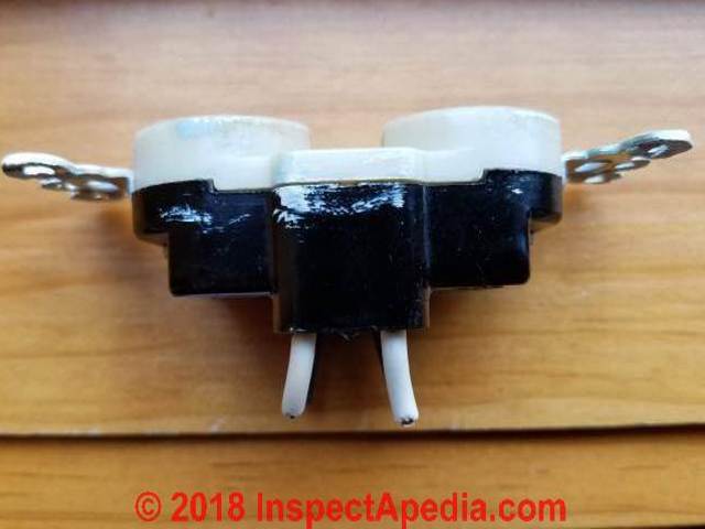
We do not recommend using the push-in back-wire connection that relies on a simple spring-clip device inside the receptacle or switch because that connection has both less contact area and less clamping force on the wire.
Below our photo illustrates using the (not-recommended) push-in back-wire connection that relies only on a spring clip connector. You can see that this receptacle also offers side-mounnted binding head screws (recommended).
Watch out: We have seen field reports of receptacle burn-ups that all involved spring-clip push-in type backwire connections.
See BACK-WIRED ELECTRICAL DEVICES for a description of the types of back-wired receptacles and an opinion about which of those are most-reliable.
See BACKWIRED RECEPTACLE FAILURE PHOTOS for a detailed failure report.
The steps in connecting a wire to a binding head screw are simple but require a bit more labor than connecting an electrical wire in a screw-clamp type connector.
Both of those approaches make good connections, and you'll find that on some receptacles and switches you have only two choices: push-in spring-clip back-wiring, or using the side-mounted binding-head screw.
For those devices we recommend using the binding head screw connector.
Steps in preparing and connecting electrical wires to a receptacle or switch.
The proper wire size (for 15A or 20A circuit) and type and number of connectors have already been selected. And you've already determined which wires go to which terminal. And you already know which wires go where, as we discussed
at WHICH SCREWS GET the BLACK, WHITE & GROUND WIRES ?
and further
at WHICH WIRES GO to LINE or LOAD CONNECTIONS?
and
Watch out: electrical wiring involves fire, shock, death and other safety hazards. In many jurisdictions electrical wiring can be performed only by licensed electricians.
We recommend hiring a qualified, licensed electrican for electrical work. Even where home-owner electrical work is permitted, permits and electrical code and safety inspections are usually required. Check with your local building department.
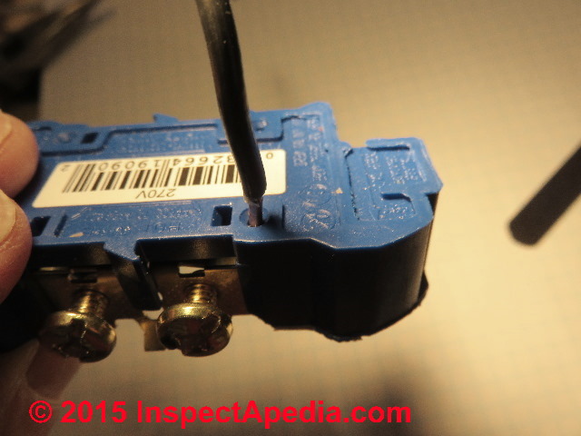
Strip the insulation from the electrical wire: how to use the wire strip gauge marked on a receptacle or switch

Above I'm showing the wire strip-back gauge area marked on the back of a 15A electrical receptacle. This gauge shows the amount of insulation that should be removed presumably for either of the types of connectors provided on this particular device. For the device shown above we are to remove from 1/2" to 5/8" of insulation, or about 16mm.
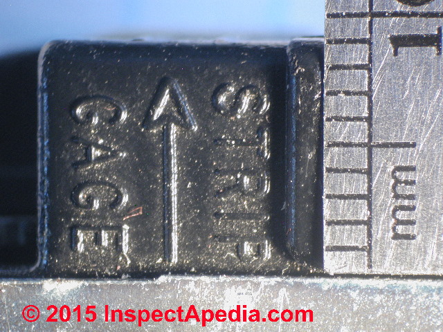
Below is a rather shorter wire stripping gauge telling us that for the device where this gauge appears - in this case a screw-clamp type wire connector, somewhat less insulation is to be removed. For the device shown below we are to remove 9mm of insulation - about 0.35" - quite a bit less insulation than for the device above.
Watch out: don't strip off too little insulation or the wire will not make a safe, reliable electrical connection: either the wire won't push far enough into the screw-clamp connector or the insluation may prevent the binding head screw from pinching the wire - it'll pinch onto the insulation instead, making a loose, poor electrical contact.
And don't strip off too much wire insulation or the extra length of bare wire may cause a short circuit when you push the device back into its electrical box. That's more than embarrassing, it's dangerous. Trust me.
Most light switches and receptacles include this indicator that tells you how much insluation the manufacturer recommends stripping off when wiring this device.
Typically we're removing from 1/2" to about 5/8" of insulation, taking care not to damage or notch the wire. It makes sense, then, to actually look at these instructions given by the manufacturer, as not all strip gauges show the same strip-back quantity.
Also see ELECTRICAL WIRE STRIPPING TIPS
Insert the Wire into the Connector OR Make a Loop for Use with the Binding Head Screw
If the wire is being inserted straight into the connector, push the stripped end into the connector skip our illustrations of making a hook or loop at the wire end, just insert the wire into the connector straight, as shown below, and go on to Tighten the Screw below.
In the photo above I've inserted the stripped copper wire into the opening between the pressure plate and the backing plate of a screw clamp type connector on a 20A electrical receptalce.
If the wire is not being inserted straight into a connector, bend the end into a hook or loop
Bend the wire into a hook for use with a binding head screw if you are using that connector.
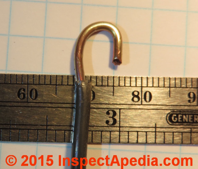
I bend the wire into a loop using pliers. I like rounded needle-nose pliers for making a nice smooth hook.
Tip: If I'm going to use the factory-provided bending lug to close this loop around the binding head screw stem then I make the open end of the hook a bit longer than shown in the photo above. That makes it easier to bend the loop shut against the lug as we will illustrate below.
If the wire is not being inserted straight into a connector, hook the wire loop around the binding head screw.
The hook is placed around the shaft of the binding head screw. With the back of the receptacle facing you, place the wire on the left side of the screw so that when you tighten the screw by turning it clockwise the screw tends to pull the wire into the connection rather than pushing it out.
Below is the result of this step. Don't foreget that we're connecting the black or "line" or "hot" wire to the brass or darker or "LINE"-marked screw connector on the receptacle.
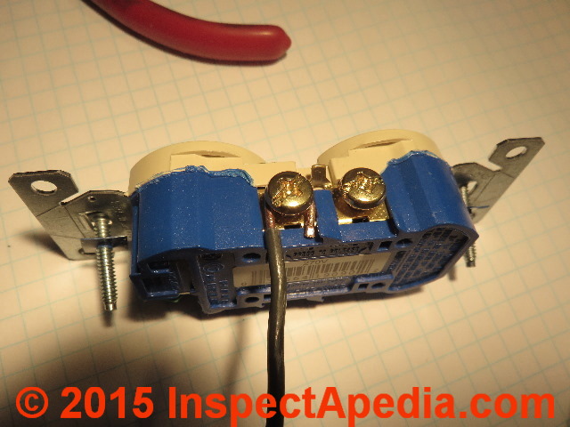
In the photo above you can see that the open end of the hooked copper wire pushes against a factory-designed raised lug or protrusion on the side of the receptacle. This feature gives a pushing surface against which the hooked wire can be pushed to close the loop.
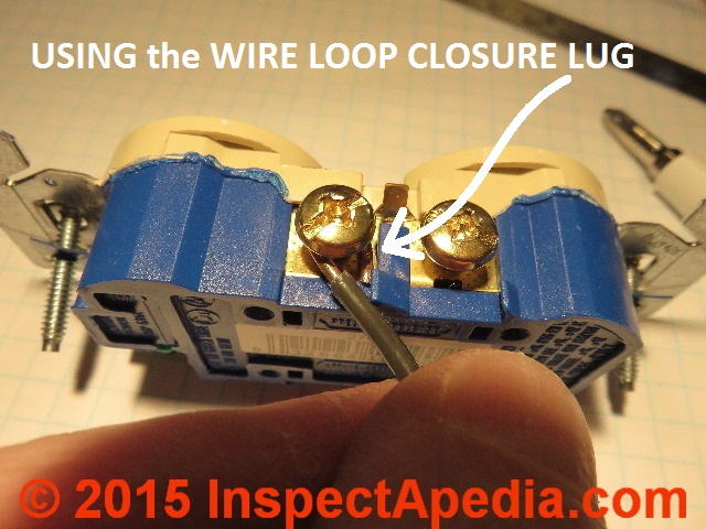
Option: close the wire loop around the binding head screw shaft. The electrician can use one of two approaches to maximize the wire-to-screw contact area, making use either of a factory-included detail that helps close the wire loop around the screw (demonstrated below), or by pinching the wire closed with needle-nose pliers.
The second of these approaches takes more time and appears to do no better than using the factory-included bending feature. To use the factory-provided wire loop closing feature present on some electrical receptacles we first strip the wire insulation, removing the amount of insulation indicated by the strip gauge on the back of the receptacle - typically about 1/2" to 9/16" of insulation is removed.
Below I'm closing the wire hook by pushing the wire towards the raised lug while the end of the wire hook remains pressing against the lug (white arrow). The photo shows the result of this simple step.
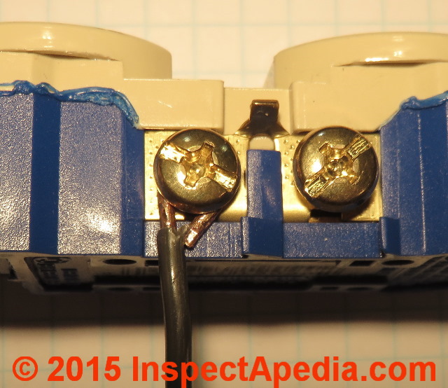
Below is this closed wire hook after I've tightened the binding head screw. Notice that before tightening the screw I returned the wire to a neat 6-O'Clock position .
In the photo below I'm using needle-nosed pliers to close the wire hook around the stem of the binding head screw. You'd use this technique if the receptacle you are wiring does not include the factory-included pressure lug demonstrated above.
As you may agree when seeing the photo below, I don't see that the pliers do any better of a job in closing the loop around the screw stem.
But closing this wire hook or loop around the screw improves both the security of the electrical connection and increases the total contact area between the screw connector and the wire. I don't see any difference, however in the contact area between using pliers or using the factory-provided bending stud available on some receptacles and switches.
Use the lug, Luke! or if there is no bending lug against which to push the wire loop or hook's open end, Use the Pliers Luke!
Tighten the screw on the receptacle or switch
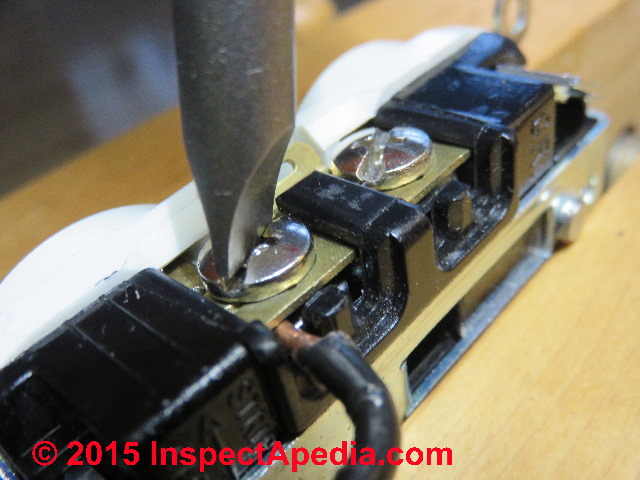
Electricians I've worked with or watched either make the screw hand tight (which turns out to be between 8 and 15 inch pounds of torque in my view), or they use a power driver which most assume applies very high torque.
In all events unless your electrical device is being held in a vise the screw tightening-torque you can apply will be limited by the fact that you're usually holding the receptacle or switch in your other hand.
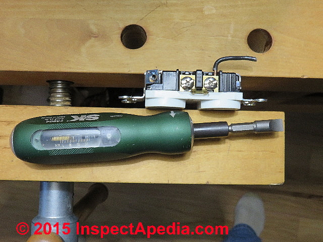
I have never once seen an electrician use a torque wrench at electrical devices like receptales and screws except for forensic engineers and other experts examining electrical connectors, but there are industry specifications for screw tightness or torque.
And for using some special connectors such as the aluminum wiring pigtail device, these torque specifications are critical to avoid failure.
See ELECTRICAL SCREW CONNECTOR TORQUE-FORCE for details and for torquin
or for torquing an AlumiConn copper pigtail connector
Watch out: it may be possible to damage the screw connector in any electrical device if you over-tighten it, particularly if using a power tool or if like me you enclosed your receptacle in a vise.
See ELECTRICAL SCREW CONNECTOR TORQUE DAMAGE for details.
Connecting the Ground Wires at the Receptacle & at the Electrical Box
Proper grounding connections for an electrical receptacle
The electrical receptacle must be properly connected to the building grounding system - not shown in our sketch.
That connection is made from the ground screw on the receptacle to the grounding conductor (usually bare copper) in the wire leading back to the electrical panel where in that location it is connected to a grounding bus and from that bus to the building grounding system, one or more earth-driven electrodes or their equivalent.
The incoming ground wire is connected to the ground terminal on the electrical receptacle (usually a green screw such as shown in our photo at left).
Details of ground wire connections for electrical receptacles are given
If you are wiring a 2-wire electrical circuit that has no ground wire, also
see 2-WIRE RECEPTACLE CONNECTIONS for proper wiring details.
How to Extend Too-Short Wires in the Junction Box when Wiring a Receptacle
Reader Question: I don't have enough wire to lower receptacles on the wall
I recently moved into a 3 1/4 story home, and I have a basement that I am trying to finish with drywall. The room is down to the studs and the electrical receptacles are about 4' up the wall.
The Romex wiring is stapled, and there isn't enough wire to lower them. It is way to much work for me to replace all of the downstairs wiring right to the breaker box, so I'm wondering if it is possible to add onto the existing wires and attach wire screws or marrets within the walls before I start adding drywall, or whether I should add some kind of junction box to contain the marreted wires in between.
My building code stipulations would differ in some cases because I live in Canada, but I just want to do the job right, and I do not want to take the chance of having any fire hazards, as I also have small children. - Dave 2/10/12
Reply: if you have to move an entire string of electrical receptacles complete re-wiring is faster and cheaper than adding a splice box for every device.
Dave,. you are correct to be careful about moving outlets or any other device when the existing wires are too short. The temptation is to just splice on an extension and bury that in the wall or ceiling: an illegal, improper, unsafe as well as really aggravating approach.
The proper approach is to add a junction box at each splice - we never splice 120/240V wires without including them in a box. You can reduce the wiring work a little by using plastic boxes instead of steel - avoiding having to also connect the box to the ground wire.
See ELECTRICAL SPLICES, HOW TO MAKE.
The proper approach also means that you don't then bury any of these splice-boxes in the walls either. Each box has to be brought to the surface and covered.
The result is a lot of work and expense and an ugly wall with an extra junction box and blind cover all along the wall over each of the now moved or lowered electrical receptacles.
Frankly I figure that especially as you've already got the wall open to the studs, if there are more than one or two receptacles to be moved you'll probably find it is actually much less total work to re-wire the entire circuit, allowing proper lengths of wires for each box. You might carefully remove and re-route the existing wire lower in the wall or you might buy all new electrical wire - depending on the age and condition of the existing materials.
Watch out: when removing wire that appears to be in good condition, if you nick the insulation you've created a new hazard.
How Many Conductors Should be in the Receptacle Circuit?
This information is now at NUMBER of WIRES NEEDED: 2-WIRE, 3-WIRE, 2 or 3 WITH GROUND?
How to Wire Multiple Receptacles ("Outlets") at One Electrical Box
This information has been moved to ELECTRICAL DUPLEX RECEPTACLE WIRING
Wiring a Split Receptacle to Two Different Electrical Circuits - option for separate receptacle control
This topic has moved to ELECTRICAL SPLIT RECEPTACLE WIRING
Reader Comments, Questions & Answers About The Article Above
Below you will find questions and answers previously posted on this page at its page bottom reader comment box.
Reader Q&A - also see RECOMMENDED ARTICLES & FAQs
On 2022-02-19 by Inspectapedia Com Moderator
@Vince,
In that case we know that you expect to find a hot or black wire and a neutral or white wire and there's no ground.
On 2022-02-19 by Vince
What there is only two wires black and white for outlet
On 2022-02-04 by Inspectapedia Com Moderator
@Danielle Cornet,
The convention that I gave before (black tape on white wire means it's being used as a "hot" wire) and your discovery of a mis-wired indicator on testing your circuit are as far a we can go with this by text.
In essence you have to trace a mis-wired circuit back to the panel, checking every junction box, splice, connection, device, until you find the mistake.
On 2022-02-04 by Danielle Cornet
@Inspectapedia Com Moderator
The switch was not controlling any outlets. I have the 3 whites on the silver and the 2 blacks and white wrapped in black on the brass. Unfortunately, I did not test the original outlet before I replaced it.
On 2022-02-04 by Inspectapedia Com Moderator
@DANIELLE CORNET,
You have probably mis-wired the receptacle: Watch out: that's unsafe, risking shock or fire.
Hot and neutral reversed means just what it says: the receptacle is mis-wired. Some appliances and other devices can be damaged by reversed hot and neutral.
Where a white wire is wrapped with black tape the electrician who did so is indicating that that particular white wire, while normally used as a neutral wire, is in this case being used as a "hot" wire - equivalent to "black". This use is made, for example when a pair of wires (white and black) are used to power a device (perhaps a receptacle or half of a receptacle) through a switch.
So what's needed now is a more-complete tracing of the wires in the circuits involved: identifying receptacles, switches, junction boxes, to be sure that the hot and neutral are properly identified, connected, and used. I suspect you're going to find that someone was using a wall switch to control a receptacle.
In the Index to Related Articles (given near the end of any of these articles) you'll find a master index that includes articles on wiring light switches, on safe use of DMMs and VOMs for wire tests, etc.
Or use our Search box on any page to find any of these articles.
ELECTRICAL WIRING BASICS
and
ELECTRICAL CIRCUIT ID, MAP & LABEL
LIGHT SWITCH WIRING DETAILS
DMMs VOMs SAFE USE OF
are all worth a read
Watch out: if you are not trained in proper electrical wiring you could make a mistake that could shock or kill someone or cause a building fire. So don't be embarrassed or reluctant to bring in a professional as needed.
On 2022-02-04 by DANIELLE CORNET
I have 3 sets of wires in an outlet that I was replacing. One of the white wires is marked with black tape. After wiring it, it reads hot/neutral reverse. My whites are on silver screws and my blacks are on brass screws.
Another outlet that I have not replaced in the adjacent wall / different room reads hot/neutral reversed. Any suggestions how to correct this?
On 2021-10-15 by Inspectapedia Com Moderator
@CS,
Watch out: if you're not familiar with safe and proper electrical wiring you could be shocked or killed - get help before either of those occur.
Now nobody here at InspectApedia is going to bet your life on telling you what wires are from our remote place here in Minnesota.
But IF the installer of the original circuit followed typical North American wiring convention,
Black = hot
Red = hot
White = neutral
Green or bare = ground
This may be a multi-wire branch circuit used to permit wiring adjacent kitchen electrical receptacles ("outlets" in your note) such that adjacent receptacles are on different circuits, thus providing at least two separate 20A circuits to the kitchen where we often need to plug in and run a lot of stuff at once, AND for convenience, wiring such that in a quad of receptacles, or even within the same individual receptacle we wire the adjacent receptacles on the two different hot legs (two different breakers in the panel, 2 different circuits, maybe both sharing the same neutral and ground)
Take a look at the old recpetacle; were the brass or copper tabs between the receptacles upper and lower connector or"plug receptacle" broken off to electrically separate top from bottom "outlets"?
If so then the electrician would have powered one, perhaps the top with black and the other, bottom, with red, and used the same neutral for both and same ground for both
OR
If that was not the case then perhaps your receptacles were installed as quads (4 "plug-ins" or two actual receptacles, side by side in a single electrical box).
If this alternative is your case, then the black hot would have powered one receptacle (both top and bottom tab between top and bottom left intact, not removed)
and
the red hot would have powered the adjacent receptacle of the pair.
Watch out: I DO NOT KNOW if this is how your receptacles were wired, I'm simply describing common practice for kitchens,
By wiring nearby or adjacent receptacles onto two different 20A circuits we can, for example, plug in a microwave and a toaster at the same general countertop area, and run them both at once without tripping a circuit breaker as we've put them on different circuits.
On 2021-10-15 by CS
i am replacing a kitchen outlet. It has one each of red, white, black . And a ground. How do I wire this. I think it was done incorrectly before as the outlet blew and is not working.
On 2021-04-03 by Anonymous
@danjoefriedman,
Thank you
On 2021-04-02 by danjoefriedman (mod)
@Anonymous,
The first GFCI in a string of daisy-chained receptacles is wired to the LINE side and its output that feeds additional receptacles "downstream" from itself are wired to its LOAD terminals.
Watch out: if you are not familiar and trained in safe proper electrical wiring you could be shocked or killed.
On 2021-04-02 by Anonymous
I have a junction box connected to two different GFI plugs. Is my connection on the first a line or load?
On 2021-02-07 by danjoefriedman (mod)
Kirk: to wire that GE ZW 1001 as shown, you'd use a twist-on connector to splice together
Black: incoming-hot, outgoing-hot, and black "hot" pre-wired to the receptacle
White: incoming-neutral, outgoing-neutral, and white "neutral" pre-wired to the receptacle
The green ground wire must be connected to the incoming circuit ground (bare copper wire) that was shown in your first photo, and that incoming ground must also connect to the metal electrical receptacle box shown in your first photo; there is usually a pre-tapped screw in that box that accepts a green ground connector screw or there are box side-clips for ground wires that can work.
More on that last item is at GROUND WIRE CONNECTIONS
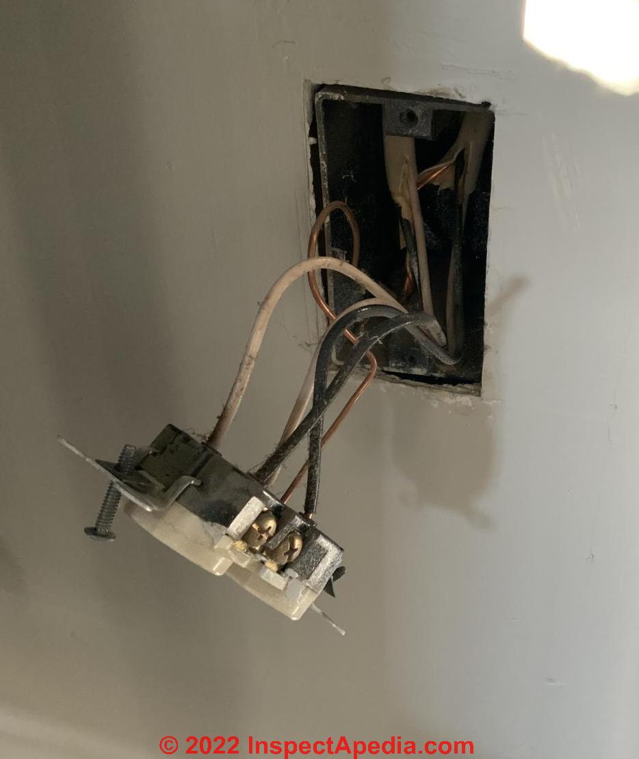
On 2021-02-07 by danjoefriedman (mod)
Kirk: IMO, your copy of your receptacle hanging out from the wall is in effect an example of "daisy-chained" electrical "outlets" because power enters at one terminal on the receptacle, flows through the brass connector to a second screw on the same receptacle, and thence onwards to the next receptacle "downstream" from this one.
Watch out: I note that the receptacle is back-wired: not a reliable connection over time. See our warnings at
BACK-WIRED ELECTRICAL DEVICES
If power in to this receptacle is interrupted so will be power interrupted to all of the receptacles "downstream" from it.
On 2021-02-07 by Kirk
3-lead replacement outlet (GE ZW 1001). Z-wave.
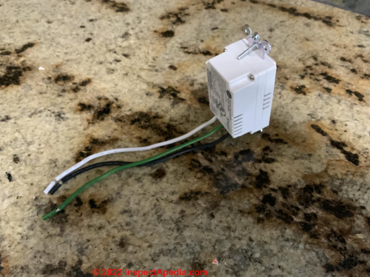
Looks like a daisy chain.
On 2021-02-03 by danjoefriedman (mod)
Kirk
I can't tell from your note if your original wiring was bringing separate elecrical power to the upper and lower receptacle outlets OR if the installer simply used the second pair of terminals to continue the circuit on to the next receptacle in a daisy-chain of tem.
If you know how to use a DMM or VOM you can determine if just one or both black wires are hot - that'll answer that question.
If the circuits were daisy chained then you'd splice the wires as needed in the box.
But I'm unsure what sort of replacement receptacle you've bought as your description doesn't match any conventional duplex elecrical receptacle with which I'm familiar.
Use the "Add Image" button (one image per comment) to give us a look at the old and new receptacles.
Watch out: if you're not familiar with proper electrical wiring practices you could cause a fire or get shocked or killed.
On 2021-02-01 by Kirk
I'm replacing an outlet that currently has two black wires connected to two separate terminals and also two white wires connected to two separate terminals. There's one ground wire. The new outlet only has one black and one white terminal (and ground). How should I connect the black and white wires?
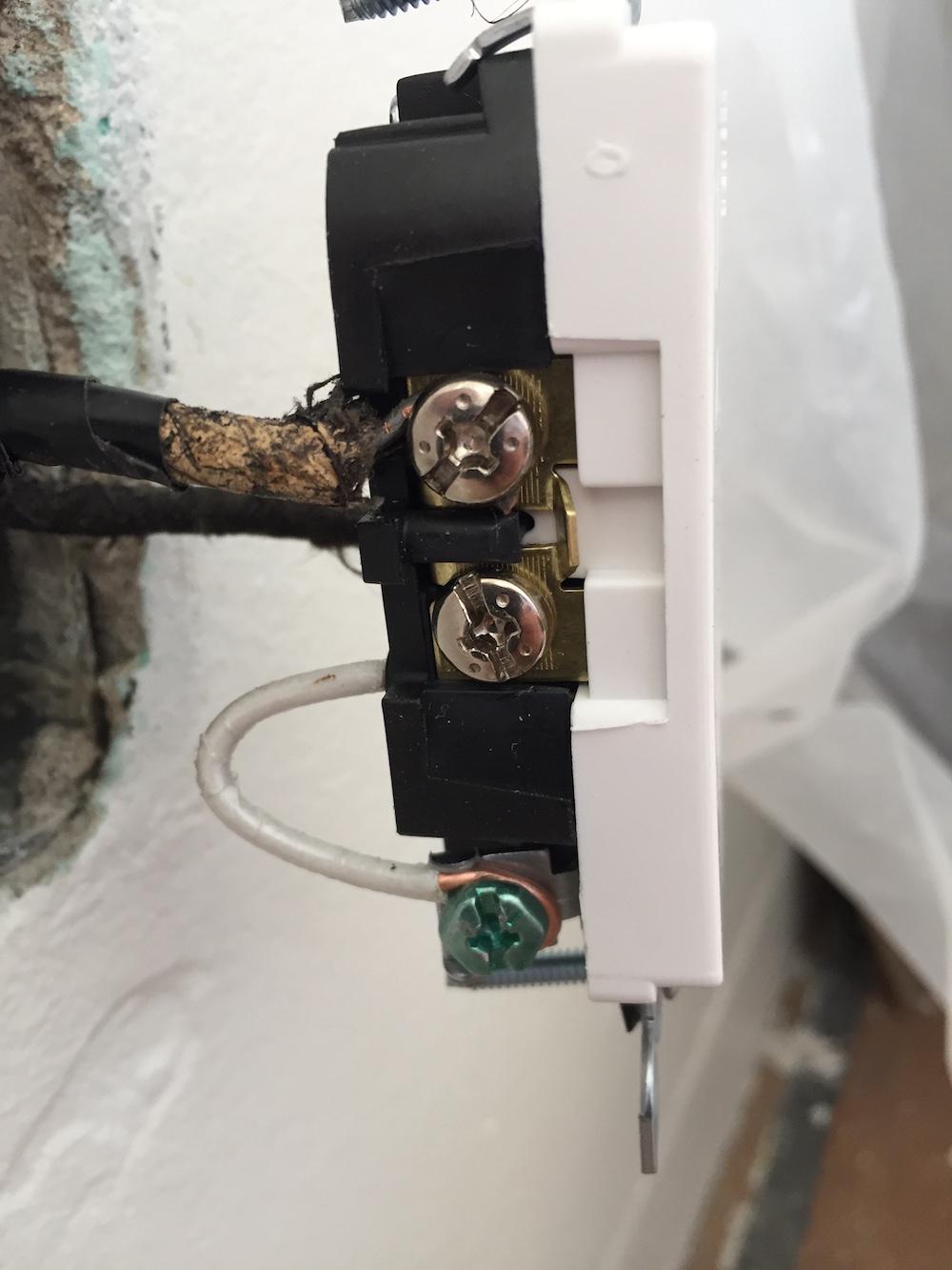
On 2020-07-12 - by (mod) - unsafe, improper electrical receptacle wiring: neutral connected to ground terminal
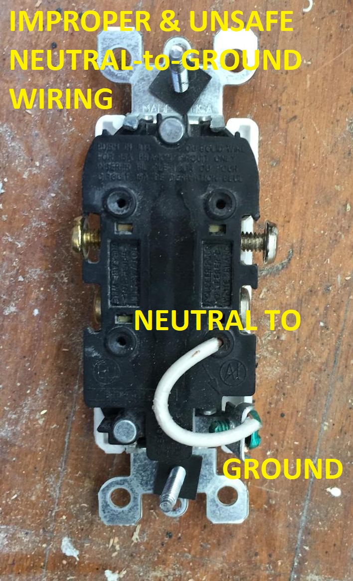 Sure Jaco, thanks for an important question and photos.
What I see is incorrect, illegal, and very dangerous wiring at an electrical receptacle: someone installed a "jumper" between the neutral side of the receptacle (using the push-in wiring connector) and the receptacle's green grounding conductor connection screw.
The reasons that this is dangerous include at least:
1. We know that there is a wiring error somewhere on this circuit and that most-likely someone did a "work-around" to force the receptacle to "work" by providing a path from neutral direct to ground.
So somewhere this circuit is mis-wired or damaged and thus we've left a fire or shock hazard un-repaired in the building.
2. The grounding conductor or "ground wire" at a receptacle is not intended to carry current continuously; it's there as a safety device.
In some buildings, such as where metal or armored cable wiring is used, this connection makes the BX metal jacket electrically live. Someone touching the BX cable exterior and also touching ground (like a water pipe or standing on a wet floor) could be badly shocked or even killed.
3. Watch out: when we see makeshift and incorrect electrical wiring at one spot in a building we need to be alert for other mistakes elsewhere, in electrical wiring and possibly on other systems; those, too, may be unsafe.
On 2020-07-12 by jaco
What the heck is this? [Photos above & below.]
On 2020-03-30 - by (mod) - how to wire a GFCI when there are multiple hot wires
 Don:
Don:
Watch out: if you are not familiar with safe and correct electrical wiring it's important to get help from a qualified person like an electrician. Making a mistake can kill you or burn down the house.
That standard warning given, typically one of the black wire will be the circuit "hot" feed and paired with it will be the circuit neutral.
At a light switch the electrician often uses a pair of wires to wire the light switch to and from a light fixture (or switched receptacle).
When installing a GFCI (Ground Fault Circuit Interrupter) receptacle, it is critical that the incoming "hot" and "neutral" be connected to the proper terminals (usually indicated by "LINE" on one pair of terminals on the GFCI device.
If you need to feed other electrical devices (like a light, switch, or downstream electrical receptacle) those wires (hot and neutral) are connected to the "LOAD" terminal on the GFCI.
Mis-wiring, particularly swapping the LOAD and LINE wire connections on GFCI's has been such a notorious problem that newer GFCIs like the one in my photo below are sold with a yellow tape over the LOAD terminals in hope that the installer will be forced to connect the LINE wires (hot and neutral) to the proper connection screws on the device.
See details at GFCI DEVICE SELECTION & WIRING https://inspectapedia.com/electric/GFCI-Installation-Procedure.php
On 2020-03-30 by Don
Installing a GFIC and a single light switch in a box that has three black wires and two white wires
On 2020-03-19 - by (mod) - this electrician carries a torque wrench
Thanks for the important comment, Mink, on torquing electrical connections. From my experience you are in a minority - but the right one.
I've spoken with several thousand inspectors and hundreds of licensed electricians about this topic and have found virtually none of them even carries a torque wrench.
Aronstein's work on this topic found some subtle but important snafus such as the binding of a steel screw in an aluminum terminal block that can fool the installer into thinking that the connection against the wire is properly tight when in fact the wire is quite loose - arcing and overheating later-on.
So we are in complete agreement that proper torquing is important, though apparently rarely-done.
On 2020-03-19 by Mlnk - 12 to 14 inch pounds for receptacles and switches
I am an electrician. Please read NEC 120-14. I torque every electrical connection, lugs, circuit breakers, receptacles, switches to factory specs with a Belleville washer, torque wrench Or torque screwdriver.
Leviton specs 12 to 14 inch pounds for receptacles and switches. Too loose Leads to arcing. Over torquing damages the threads and Gradually becomes loose. Torque screwdrivers cost about $60.
On 2018-02-03 - by (mod) - the white "in" wire and black "out" wire is connected on same side.
This sounds like mis-wiring or reversed polarity.
IF your receptacle has not had a tab broken away on each side, the two screws on each side are "common" electrically, connected by a brass strip.
The two silver screws get the white neutral wires
The two brass colored screws get the two black hot wires.
Why two wires on each side:
Typically of the two black wires one will be "hot" or live - the incoming power, and the other is the hot wire being used to power a device that is downstream from the receptacle you're seeing.
The white wire paired with the incoming hot black is the incoming neutral.
Sometimes I find that an installer reversed wires out out of their normal, proper connections rather than tracking down a mis-wired reverse-polarity issue that is upstream from the place where she/he is working.
Also see REVERSED POLARITY ELECTRICAL DEVICES / CIRCUITS
Watch out: doing electrical wiring if you are not trained and qualified risks fire, shock, death.
On 2018-02-03 by Brad Connot
Went to change a 3-2 prong outlet and the white "in" wire and black "out" wire is connected on same side. Same with the other side......can't seem to find why this works
...
Continue reading at GROUND WIRE CONNECTIONS or select a topic from the closely-related articles below, or see the complete ARTICLE INDEX.
Or see ELECTRICAL RECEPTACLE CONNECTION FAQs - questions & answers about wiring electrical outlets
Or see these
Recommended Articles
- ELECTRICAL OUTLET, HOW TO ADD & WIRE - home
- 2-WIRE ELECTRICAL RECEPTACLE CONNECTIONS
- BACK-WIRED ELECTRICAL DEVICES
- ELECTRICAL BOX GROUND WIRING
- ELECTRICAL BOX RECESSED DEPTH IN WALLS
- ELECTRICAL BOX FIRE SEPARATION DISTANCES
- ELECTRICAL DUPLEX RECEPTACLE WIRING
- ELECTRICAL OUTLET ADAPTER SHORT CIRCUIT
- ELECTRICAL OUTLET HEIGHT ABOVE FLOOR
- ELECTRICAL OUTLET, HOW TO ADD in OLDER HOME
- ELECTRICAL RECEPTACLE ARC PITTING
- ELECTRICAL RECEPTACLES for 30A 240VAC CIRCUITS
- ELECTRICAL RECEPTACLE CONNECTION DETAILS
- ELECTRICAL RECEPTACLE COUNTERTOP SPACING
- ELECTRICAL RECEPTACLE COVER PLATES
- ELECTRICAL RECEPTACLE HEIGHT & CLEARANCES
- ELECTRICAL RECEPTACLE LOCATIONS
- ELECTRICAL RECEPTACLE POSITION: WHICH WAY UP
- ELECTRICAL RECEPTACLE TYPES
- ELECTRICAL RECEPTACLE WIRING SERIES vs PARALLEL
- ELECTRICAL WIRE CLEARANCE FROM DUCTS & PIPES
- GROUND WIRE CONNECTIONS
- OLD WORK ELECTRICAL BOXES for RETROFIT
- REVERSED POLARITY ELECTRICAL DEVICES / CIRCUITS
- ROUTING, SECURING & PROTECTING ELECTRICAL WIRES
- SIZE of WIRE REQUIRED for ELECTRICAL RECEPTACLES
- SPLICING ELECTRICAL WIRES
- STRIPPING ELECTRICAL WIRES
- ELECTRICAL WALL PLUG WIRING ID & CONNECTIONS
- LIGHT SWITCH WIRING DETAILS
- SAFETY for ELECTRICAL INSPECTORS - home
Suggested citation for this web page
ELECTRICAL RECEPTACLE CONNECTION DETAILS at InspectApedia.com - online encyclopedia of building & environmental inspection, testing, diagnosis, repair, & problem prevention advice.
Or see this
INDEX to RELATED ARTICLES: ARTICLE INDEX to ELECTRICAL INSPECTION & TESTING
Or use the SEARCH BOX found below to Ask a Question or Search InspectApedia
Ask a Question or Search InspectApedia
Try the search box just below, or if you prefer, post a question or comment in the Comments box below and we will respond promptly.
Search the InspectApedia website
Note: appearance of your Comment below may be delayed: if your comment contains an image, photograph, web link, or text that looks to the software as if it might be a web link, your posting will appear after it has been approved by a moderator. Apologies for the delay.
Only one image can be added per comment but you can post as many comments, and therefore images, as you like.
You will not receive a notification when a response to your question has been posted.
Please bookmark this page to make it easy for you to check back for our response.
Our Comment Box is provided by Countable Web Productions countable.ca
Citations & References
In addition to any citations in the article above, a full list is available on request.
- Timothy Hemm has provided photographs of various electrical defects used at the InspectAPedia TM Website. Mr. Hemm is a professional electrical inspector in Yucala, CA.
- Mark Cramer Inspection Services Mark Cramer, Tampa Florida, Mr. Cramer is a past president of ASHI, the American Society of Home Inspectors and is a Florida home inspector and home inspection educator. Mr. Cramer serves on the ASHI Home Inspection Standards. Contact Mark Cramer at: 727-595-4211 mark@BestTampaInspector.com
- John Cranor [Website: /www.house-whisperer.com ] is an ASHI member and a home inspector (The House Whisperer) is located in Glen Allen, VA 23060. He is also a contributor to InspectApedia.com in several technical areas such as plumbing and appliances (dryer vents). Contact Mr. Cranor at 804-873-8534 or by Email: johncranor@verizon.net
- [3] NFPA - the National Fire Protection Association can be found online at www.nfpa.org
- [4] The NEC National Electrical Code (ISBN 978-0877657903) - NFPA might provide Online Access but you'll need to sign in as a professional or as a visitor)
- US NEC Free Access: See up.codes at this link: https://up.codes/code/nfpa-70-national-electrical-code-2020
- [5] Special thanks to our reader Steve who pointed out prior errors in our illustrations.
- [6] Simpson Strong-Tie, "Code Compliant Repair and Protection Guide for the Installation of Utilities in Wood Frame Construction", web search 5/21/12, original source strongtie.com/ftp/fliers/F-REPRPROTECT09.pdf, [copy on file as /Structures/Framing/Simpson_Framing_Protectors.pdf ]. "The information in this guide is a summary of requirements from the 2003, 2006 and 2009 International Residential Code (IRC), International Building Code (IBC), International Plumbing Code (IPC), International Mechanical Code (IMC), 2006 Uniform Plumbing Code (UPC) and the 2005 National Electrical Code."
- "Electrical System Inspection Basics," Richard C. Wolcott, ASHI 8th Annual Education Conference, Boston 1985.
- "Simplified Electrical Wiring," Sears, Roebuck and Co., 15705 (F5428) Rev. 4-77 1977 [Lots of sketches of older-type service panels.]
- "How to plan and install electric wiring for homes, farms, garages, shops," Montgomery Ward Co., 83-850.
- "Simplified Electrical Wiring," Sears, Roebuck and Co., 15705 (F5428) Rev. 4-77 1977 [Lots of sketches of older-type service panels.]
- "Home Wiring Inspection," Roswell W. Ard, Rodale's New Shelter, July/August, 1985 p. 35-40.
- "Evaluating Wiring in Older Minnesota Homes," Agricultural Extension Service, University of Minnesota, St. Paul, Minnesota 55108.
- "Electrical Systems," A Training Manual for Home Inspectors, Alfred L. Alk, American Society of Home Inspectors (ASHI), 1987, available from ASHI. [DF NOTE: I do NOT recommend this obsolete publication, though it was cited in the original Journal article as it contains unsafe inaccuracies]
- "Basic Housing Inspection," US DHEW, S352.75 U48, p.144, out of print, but is available in most state libraries.
- In addition to citations & references found in this article, see the research citations given at the end of the related articles found at our suggested
CONTINUE READING or RECOMMENDED ARTICLES.
- Carson, Dunlop & Associates Ltd., 120 Carlton Street Suite 407, Toronto ON M5A 4K2. Tel: (416) 964-9415 1-800-268-7070 Email: info@carsondunlop.com. Alan Carson is a past president of ASHI, the American Society of Home Inspectors.
Thanks to Alan Carson and Bob Dunlop, for permission for InspectAPedia to use text excerpts from The HOME REFERENCE BOOK - the Encyclopedia of Homes and to use illustrations from The ILLUSTRATED HOME .
Carson Dunlop Associates provides extensive home inspection education and report writing material. In gratitude we provide links to tsome Carson Dunlop Associates products and services.
 | HOME | ABOUT | ASK a QUESTION | CONTACT | CONTENT USE POLICY | DESCRIPTION | POLICIES | PRIVACY | |
| © 2024 - 1985 Publisher InspectApedia.com - Daniel Friedman | |||||||||