 Backwiring Electrical Receptacles (wall plugs) & Switches
Some back-wired electrical devices perform well, but some push-in devices may be unsafe
- POST a QUESTION or COMMENT about how to install and wire electrical outlets or receptacles in buildings.
Back wired electrical receptacles:
Using the back-wire or push-in type connection points on an electrical receptacle or switch may be just fine, or it may not be reliable nor safe, depending on the age and type of back-wire connector provided.
Here we describe the types of backwire connectors used on electrical receptacles and light switches and we explain the safety and performance questions that may arise.
This article series explains receptacle types, receptacle grounding, connecting wires to the right receptacle terminal screws, electrical wire size, electrical wire color codes, and special receptacles for un-grounded circuits.
InspectAPedia tolerates no conflicts of interest. We have no relationship with advertisers, products, or services discussed at this website.
- Daniel Friedman, Publisher/Editor/Author - See WHO ARE WE?
Performance of Push-In, Back-Wired Electrical Devices: receptacles & switches
 Article Series Contents
- BACK-WIRED ELECTRICAL DEVICES - home
- BACKWIRED RECEPTACLE FAILURE PHOTOS
- BACKWIRED RECEPTACLE FAILURE REPORT
- RECEPTACLE WIRE-TO-CONNECTOR CONTACT AREA SIZES
- WIRE-TO-CONNECTOR FORCE COMPARISONS
- WIRE-TO-CONNECTOR PERFORMANCE SUMMARY
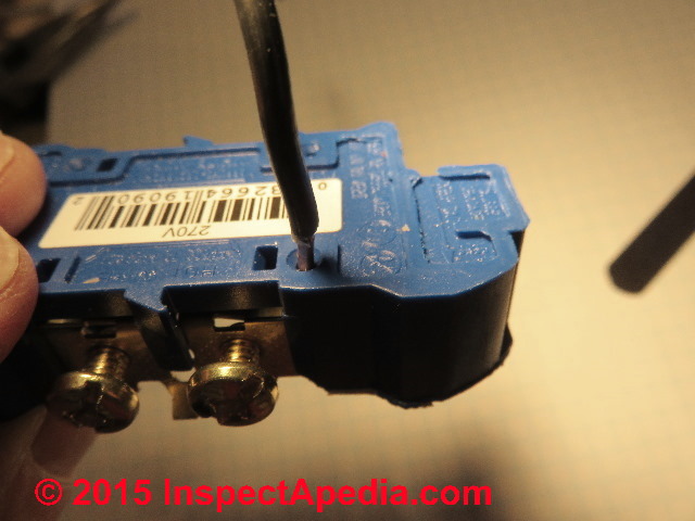
At left we illustrate a #14 solid copper wire being pushed into the backwire opening of a common electrical receptacle. The wire has not been pushed fully into the connection as I wanted to show the diameter of the wire entering the push-in connector opening.
This article illustrates and explains possible electrical failures and fire risk when using the push-in rear connectors on some back-wired electrical devices such as receptacles and switches.
We illustrate the typical connector used in some receptacles and switches that accept a simple push-in connection usually found on the rear of the device. The rectangular opening is used to release an installed wire. Simple screw terminals are also visible in the lower left of the photo.
Four Types of Push-In, Back-Wired Electrical Devices: receptacles & switches
1. Push-In or Conventional Binding-Head Screw Back-Wired Receptacles
A lower price ($0.69 U.S.D.) push-in type back-wired receptacle purchased at a Home Depot store in 2015 is illustrated above.
Above the photo gives view of the neutral wire side screw connectors and a green grounding conductor connector screw.
[Click to enlarge any image]
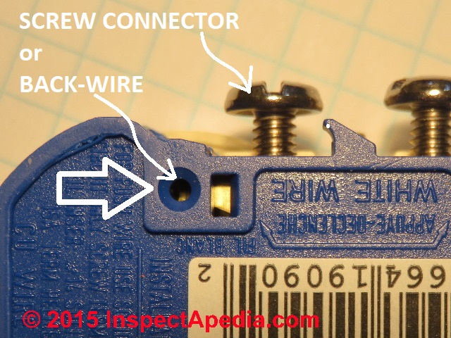
Just above you can see on the back of this device the round opening that accepts a push-in connection of a #14 solid copper wire (white arrow).
The small rectangular opening permits insertion of a probe to open the spring clip to release wires that have been installed through the round opening.
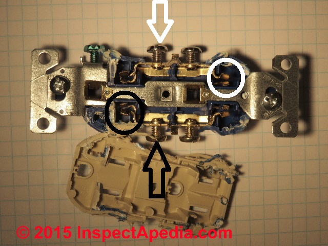
We disassembled the push-in backwire receptacle shown above to permit a view of the wire connections inside this device
. In the photo at below left, and viewed from the front with the electrical receptacle's plastic front cover removed, the white and black arrows indicate the side screw connectors while the white and black circles show the interior location of the push-in spring-clip connectors.
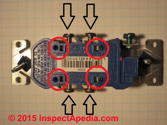
However wires are pushed in from the other side - the "back" of this device as I show below.
Below at left is a close-up of the spring clip connector.
Click to enlarge this image and you'll see that the end of the spring clip has a rounded notch (red arrow) that I think is intended to increase the contact area and security of spring grip on the wire when it's pushed through this opening.
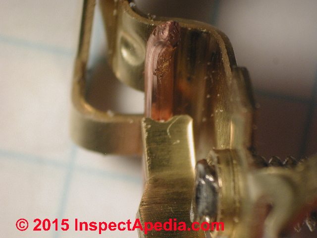
Below you can see a high magnification (stereo microscope) photo of the areas of contact between a relatively-straight copper wire and the spring clip connector surfaces.
There are two points of electrical contact with the wire: the notched end of the spring blade (red arrows in the photographs above) and the side contact plate against which the wire is pushed (green arrow).
Details about this connection and a discussion of wire-to-device contact area and contact force are given below
at BACKWIRED DEVICE SPRING CLIP DETAILS
2. Screw-Clamp Type Back-Wired Electrical Receptacles
[Click to enlarge any image]
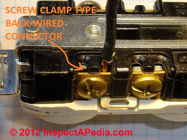
Modern back-wired electrical devices like receptacles and light switches use a clamp-type screw and plate that permits very good contact between the electrical connector on the device and the wire - as shown in our photograph at above-left.
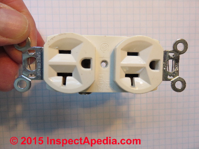
With wires stripped to the proper length, not nicked, and with the screw tightened, these are, in our OPINION, good electrical connections. Shown at above left is a FS Spec Grade 20-Amp 120V electrical receptacle listed by UL, CSA, and other agencies.
This device is marked as suitable for copper wire only.
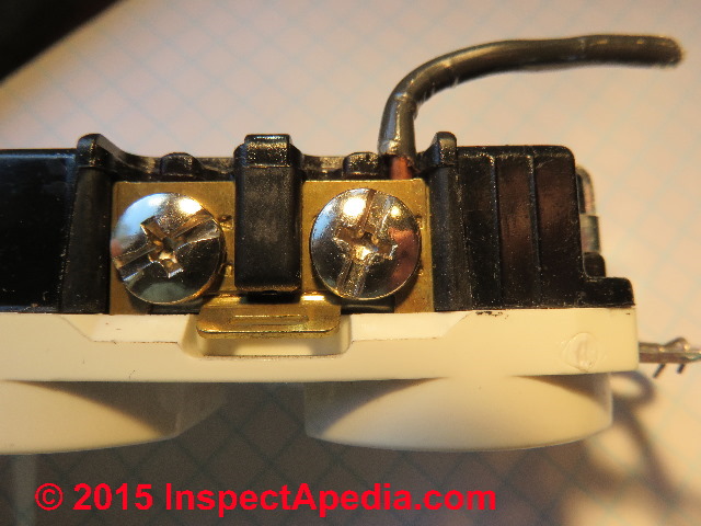
At above right is a top view of a #12 copper wire inserted into one of the clamp type electrical receptacle openings. At right in the same photo you can see the silver edge of the clamp pushed against the copper plate beneath the screw when the device is fully closed.
Watch out: to make proper use of this electrical connector on a receptacle you must be sure to insert the electrical wire between the silver coloured clamp and the inner face of the copper screw plate.
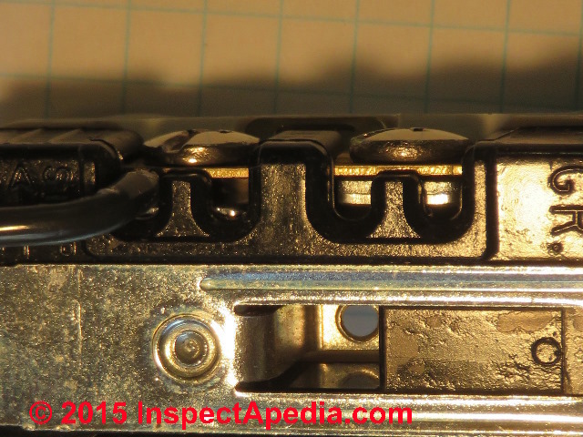
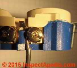
Otherwise when you tighten the connector screw it will not clamp onto the wire. A close-up view of the wire inserted properly into the screw-clamp connector is shown at below right.
Definition of "FS" and "FD" electrical boxes & devices: The label "FS" on an electrical device indicates (F) it is suitable for mounting on a metallic ("ferrous") electrical box and (S) indicates it will fit in a shallow box.
Other devices may be labeled "FD" indicating "Ferrous" and "Deep" electrical boxes.
An "FS" type electrical box has a minimum depth of 1 3/4" and 13.5 cubic inches and can accept up to 6 #14 or 6 #12 electrical wires.
An "FD" type electrical box has a minimum internal depth of 2 3/8", 18.0 cu. in., and can accept up to 9 #14 wires or 8 #12 gauge wires. - NEC Table 314-16 (A)
- Eaton Crouse-Hinds, "Switch & Outlet Boxes - Technical Data", Eaton Crouse-Hinds Commercial Catalog (2015), www.crouse-hinds.com, Tel: US: 1-866-764-5454, Canada: 1-800-265-0502. Excerpting from NFPA 70-2005, the National Electrical Code (2005), National Fire Protection Association (NFPA), Quincy MA 02269.
- NEC Table 314.16 (A) Metal Boxes
- U.S. National Electrical Code NEC Article 314 that covers the installation and use of electrical boxes.
- Also see "NEC Article 370, Outlet,Device, Pull and Junction Boxes, Conduit Bodies and Fittings" for a mention of this appellation, including the excessively cited text "Boxes such as FS and FD or larger cast or sheet metal boxes are not classified as conduit bodies."
3. Older Back-wire Only Dual-Wire (#12 or #14) Push-in-ONLY Back-Wired Electrical Receptacles
Older electrical receptacles and light switches and some lower-cost modern products use a spring-clip type contact that presses the mere edge of a metal spring or clip inside the device against the edge of a wire that is pushed into the device through a hole on the device back.
These devices offer two different methods of connecting wires: through use of a binding head screw usually found on the device side, or through a simple push-in connector on the device back.
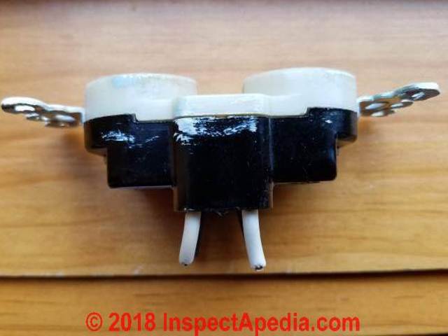
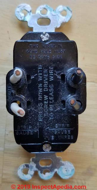
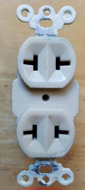
Notice that the electrical receptacle shown above sports only push-in type backwire connections. In my second photo you can see that on this receptacle no side screws and no screw clamp options were provided. This receptacle photo was taken in a Minnesota home built in 1962.
Below is a photo of back or "wiring-side" of this electrical the backwire-only type electrical receptacle. You can see from these images that that only accept back-wired push-in wire connections were provided. There are no screw terminals for wire connections.
The back-wiring holes in this receptacle accepted either #12 or #14 wire, but used a common spring for each pair of holes. If a #12 wire was pushed into one hole and a #14 in the other hole of the pair, the #14 wire would not be gripped by the spring.
The manufacturer's embossed text on the receptacle back surface warns Two Wires in Same Hole Must Be Same Size. Back-wire receptacles like this one above are no longer sold in North America.
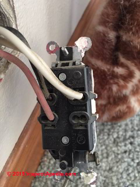
Typically these electrical switches or receptacles are referred to as "backwired" if the push-in connectors on the device back surface are used to make electrical wiring connections. An example of a back-wired electrical receptacle is shown at above-right.
Most-likely this receptacle was a split-wired unit - note the red and black wires on the receptacle's left or "hot" side and the common neutral wire in and out of the receptacle on its neutral side. This image was contributed by reader J.K.
These devices provide less electrical contact area between the device electrical connector and the wire surface than the clamp type connector, but are code-permitted and may work acceptably provided that the devices are not re-used.
That is, in our OPINION, if you remove and reinsert wires in devices that rely on a spring clip rather than a screw and plate clamp connector, the spring may be weakened and the connection less reliable.
Still older receptacles and switches (shown at left, no longer sold in the U.S. or Canada) used a hole diameter on the device back that would accept either No. 12 or No. 14 copper wire to be connected by a push-in back-wired connection method (red arrows).
Not only did these devices sport a limited electrical contact between the wire and the connector (just the edge of a flat spring in contact with the edge of a round wire), but worse, if a device was back-wired using No. 12 wire and later re-used with smaller diameter No. 14 wire, the contact spring, having been bent open by the No. 12 wire, performed poorly against a No. 14 wire later inserted into the same opening.
In our OPINION these older devices were less reliable, less safe, and should not be used by backwiring. The devices would perform acceptably, however, if the screw connectors on the device side were used to connect the wires.
Also see WIRE CONNECTIONS IF NO SCREW COLOR CODES or NO SCREWS
4. Binding Head Screw Connectors on Electrical Receptacles & Switches
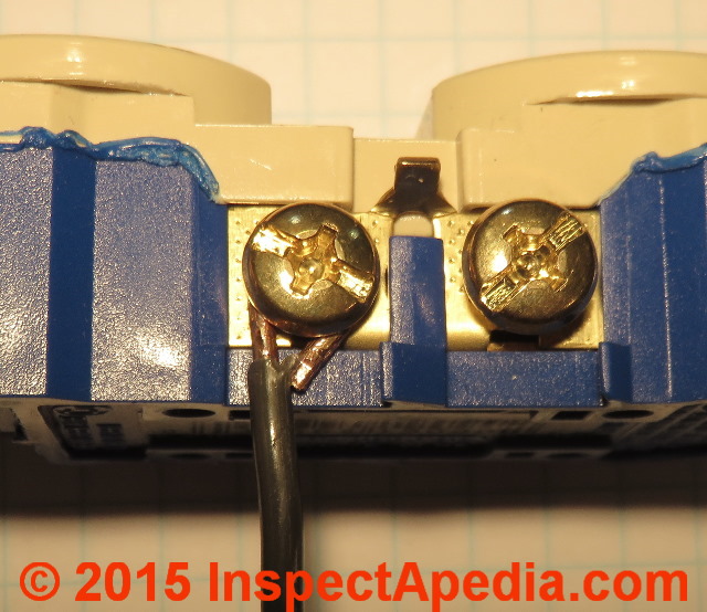
Above is a typical connection of a #14 copper wire to the binding head screw of a 15A electrical receptacle. Most electrical receptacle models that offer a back-wiring option also offer a screw or screw-clamp option.
At WIRE-TO-CONNECTOR PERFORMANCE SUMMARY we suggest that binding head screw connections such as shown here are likely to be significantly-better performers over the life of the electrical system in a building, adding that screw-clamp connectors also perform well.
Watch out: not all screw terminals on receptacles and switches used a "binding head". The binding head screw has machined grooves or teeth on the under-side of the screw head. Those are intended to get a secure bite on the wire surface as well as to cut through any slight oxidation that might be present.
But some (usually cheaper-device) screw heads are smooth on their under-side. Those are not binding-head screws and they do not make as-reliable a wiring connection.
Above is the same electrical device and binding head screw connection with a variation: we closed the hook or loop around the screw either by pushing the open end of the loop against a plastic or metal protrusion on the right side of the screw or by using pliers. This detail provides a still more-secure electrical wire connection and a bit more electrical contact area between the screw and the wire.
Electrical Wire to Receptacle Connector Type Service Life Performance Comparisons
This discussion has moved to its own page at WIRE-TO-CONNECTOR PERFORMANCE SUMMARY
For electrical receptacles and switches that offer a choice of using a push-in type spring-clip backwire connector and using a binding head screw connector to connect a No. 14 copper wire to the device, the overall quality and thus long term reliability of the electrical connection made by the combined effects of contact area (wire to connector) and contact force (wire to connector) under a binding head screw is between 300x (straight wire) and 750x (wire not straight) better than that obtained using the push-in spring-clip connector.
For electrical receptacles and switches that offer a choice of using a push-in type spring-clip backwire connector and using a pressure-plate screw connector, other constraints kept as in the case above, the pressure plate screw connection is between 150x (straight wire) and 200x (wire not straight) likely to be more reliable in long term use.
Overall, the binding-head screw offers the best electrical wire connection quality and long term reliability, all other features being equal, because it offers the greatest bulk surface contact area and significantly-higher contact pressure. The pressure-plate connector is also likely to perform significantly better than the spring-clip connector.
Reader Question: I'm changing a wall plug and the wires are too thick to go through the holes on the back of the new device.
(June 3, 2014) William said:
I am changing a wall plug with a double plug but the wires are too thick to go through the hole of the new device. HOW can I resolve this?
Reply:
Use the screw terminals not the backward device.
Watch out. What are those large diameter wires? If aluminum you have a bigger safety hazard to address.
See BACK-WIRED ELECTRICAL DEVICES.
See ALUMINUM WIRING HAZARDS & REPAIRS - home
Reader Question: Is it safe to plug a 10-Amp A/C into an outlet that is back wired?
Is it safe to plug in an ac unit that runs 10 amps , into outlet that is backed wired, i had read that you don't like this method, the outlet is on third floor and is on a 15 amp breaker - Johnny B 5/2/w
Reply: Comparing Three Types of Backwired Receptacles: 20-A Clamp Type & 15-ASpring Type & Clamp Type Backwiring Devices
Johnny, that's an interesting question and one I'm scared to answer - by online posting one cannot assure the electrical safety of your building.
Here we will illustrate three different types of electrical receptacles that can be wired from their back-side.
Our photo (left) illustrates a spec-grade 20-Amp, 125V rated electrical receptacle that looks as if it is "back-wired" - in fact while a wire can be wrapped around the terminal screws on this device, the screw is intended to be used to tighten a rectangular brass plate against a square metal nut (silver in color) that makes a very strong and positive connection over a good area of wire surface.
This receptacle is marked on its back surface as CU Wire Only - copper only. [Click images to see enlarged details.]
That said, I agree that older, spring-type back-wired electrical connections (shown at below left) are not as reliable as connections made under a screw or clamp, as the total contact area between the back-wire spring edge and the wire surface is minimal.
Nevertheless, on a 15-A circuit using 15-A devices such as receptacles, the circuit and its devices are rated and intended to be able to support the 10-amp load you describe, so long as the sum of all of the items plugged into that electrical circuit don't overload it.
Follow-up:
Thank you for responding, my town home was built in 1999, not sure if that is considered newer or older, lights do dim though when i use 10 amp vacuum . - Johnny B.
Reply:
Backwiring electrical receptacles is a permitted installation and might be found in a 1999 home - but as we show above, there are two different approaches, the second of which is a better quality installation and is in our opinion more reliable. See the details just below.
Push-in back-wire spring connector receptacle
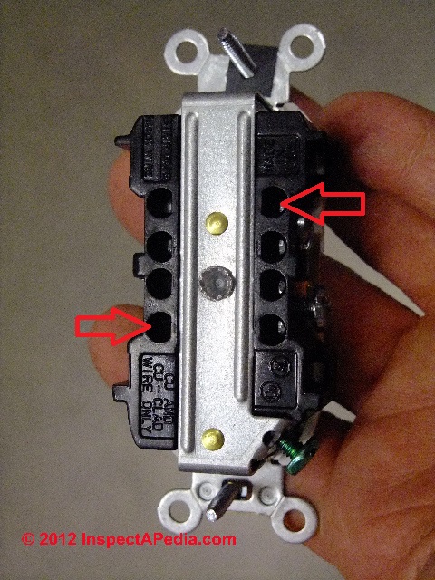
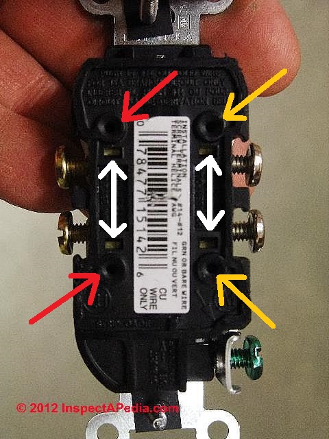
Contractor-grade 15-A spring-type-connector back-wired electrical receptacles (below left) provide a single opening at each of the four terminals (two neutral wires - yellow arrows, and two hot wires - red arrows) on the back of the receptacle.
The white arrows point to the smaller rectangular opening giving access to a press-to-release spring that will allow removal of the wire, but we prefer not to re-use this type of back-wired receptacle. Tightening the screw at the main wire terminal (blue arrow) has nothing to do with the spring-clamp that is securing the back-wired terminal wire.
You can see that this receptacle also includes two binding head screw connectors on each side - silver screws for neutral wire (right side in the photo) and brass-coloured screws for hot or black wire (left side in the photo).
I consider these screws a more secure electrical connection than the push-in backwire connectors though of course a bit more labour is involved as well.
Insert & screw-clamp 15-A back-wire receptacle connectors
Some newer heavy-duty 15-A back-wired electrical receptacles (below-left) do not rely on a simple spring-edge to contact the electrical wire, as we illustrate in our photo below.
Rather, when the wire is inserted into any of 4 receiving holes on the back of the receptacle (red arrows) on the line side (black wire) and another 4 receiving openings on the load or neutral side (white wire) of the device.
When the terminal screw is tightened that actually snugs up a clamp that contacts a much larger surface area of the back-wired wire.
That's a more secure connection mechanically. On this receptacle, instead on a single back terminal accepting a single wire, there are a pair of back terminal openings at each of the four terminal screws.
Insert & screw-clamp 20-A back-wire receptacle connectors
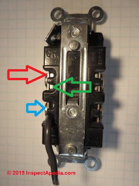
The 20-A rated electrical receptacle shown below is a variation on the 15-A pressure-clamp connector discussed just above. This receptacle dispenses with the round holes in the plastic receptacle back and exposes the wire clamps for a more clear view of what's happening.
The electrical wire (copper-only according to markings on these device) is inserted between a copper face plate (red arrow) and a thicker silver colored base plate (green arrow).
Turning the screw (blue arrow) at any of these four connectors (each of which will accept two wires) pinches the stripped wire-end between these two plates.
A comparison of crude contact areas between the copper wire and the different types of wire connectors is at RECEPTACLE WIRE-TO-CONNECTOR CONTACT AREA SIZES.
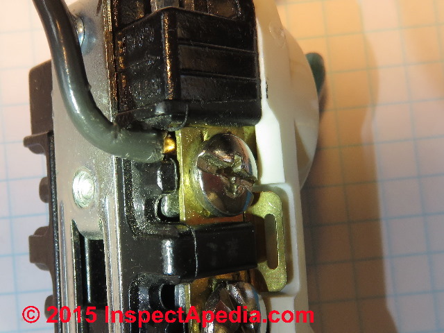
Below is a side-view of the tightened connector.
Also see ELECTRICAL SCREW CONNECTOR TORQUE-FORCE
Illustrated Details of the Push-In Spring-Clip Electrical Wire Connections at Receptacles & Switches
Reader Question: how to show the poor contact between the spring edge and wire surface of a spring-clip type back-wired receptacle or switch
10/24/2015 Markus said:
Is there a picture somewhere that shows the flimsy spring clip contact against the inserted wire? I have a hard time convincing friends that the large and secure contact area of the clamp style backwire outlet is superior to the spring clamp.
Reply:
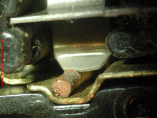
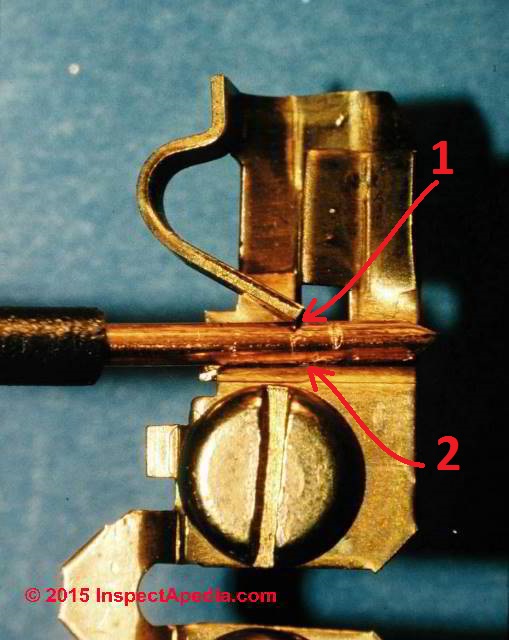 Great suggestion, Markus. It's of course difficult to photograph the poor spring-clip-to-wire contact without disassembling the receptacle as the pushed-in wire covers the opening through which the spring is visible.
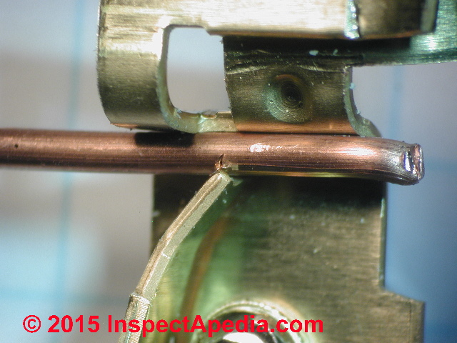
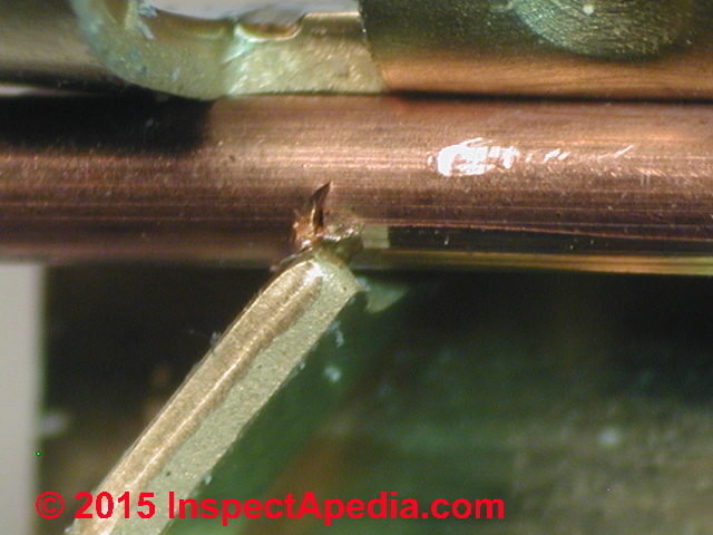
Shown at left is a close-up photograph showing the connection between the edge of a push-in type "backwire" electrical receptacle contact spring and the edge of a copper electrical wire.
The photo at left was provided by Dr. Jess Aronstein,
You can see that the contact area on the spring-side of the connector is quite small - just the point at which the edge of the spring touches the rounded surface of the copper wire.
In some of the spring clips that I've examined and not visible in the photo at left, we may find that the end of the spring clip that contacts the wire is cut out in a round profile or "notch" to increase the contact area against the rounded surface of the wire, but still the total contact area will be very small as only the edge of the angled clip touches the wire.
You can also infer that all of the spring force against the wire has to come from the arc of the copper spring.
[Click to enlarge any image]
Dr. Aronstein points out that in the connector shown at left there are two contact areas: the edge of the spring clip (red arrow #1) and possibly the larger surface area of the contact plate (red arrow #2). Certainly there will probably be at least some contact between the wire and surface #2 or the spring clip may not hold the wire in place at all.
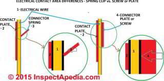
I have added a sketch below to illustrate the types of contact between the electrical wire and the connector within or on the device such as an electrical switch or receptacle.
The sketch (below) compares the wire-to-receptacle (or switch) contact area sizes of an older type flat spring with the contact area of a compression plate or screw type connector pushing against the same wire size.
Diagram of Differences in Electrical Contact Area Between Push-in Back-wire Spring Connectors and Screw / Pressure-Plate Connectors on Electrical Receptacles & Switches
In the sketch below we depict the labeled items as follows
[Click to enlarge any image]
- The electrical wire, shown in yellow
- The contact plate found in both receptacles and switches on both types of devices: push-in wired or screw-connector-wired.
This plate is found on the opposite side of the wire or sometimes partly-surrounding the wire that is held in place by ... - The connector spring in a push-in type back-wired electrical device.
You can note that on this side of the wire, the electrical contact surface between the edge of a spring clip and the surface of the wire itself (black in my drawing) is very small compared with the surface contact when a screw or clamp-type connector is used.
or - The contact plate or the under-side of the head of the screw itself on switches or receptacles that use a binding-head screw or a screw + compression plate to connect the electrical wire to the electrical device
The large and small gray-colored arrows depict differences in force between the contacting device (spring or plate or screw) and the surface of the wire.
The force exerted using a screw type connector will be significantly greater than the force exerted by the thin metal spring clip in older back wired electrical receptacles or switches.
Watch out: the older thin-spring type push-in back-wired electrical receptacle or switch hazard arises not just the very small surface area contact at the spring. After all, both types of wire-to-device connectors include a contact plate against which the spring or screw force the wire.
But in a connector-spring-type "push-in" electrical wire connector, anything that weakens the spring - itself a thin flat copper component - such as age, re-use of the electrical device, removal and re-insertion of the wire, or changing wire sizes from a #12 to a smaller $14 wire gauge or possibly even bending forces exerted by the pushed-in wires as the device is pushed back into the electrical box are likely to weaken the contact force as well.
In a binding-head screw connection, Aronstein also points out, there are again two current paths: one at the interface between the wire and the contact plate (#2 in the right-portion of the illustration above) and a second through the screw to the connector plate (#4 in the illustration above) or through the under-side of the screw head to the wire directly depending on the connector type.
In my opinion the effects and thus the benefits of the greater contact area and the greater contact force of the newer screw-type connections are additive and are features not available using the simpler spring-clip push-in type back-wired electrical connectors shown here.
Watch out: Dr. Aronstein warns (Aronstein to DF 2015) that while the screw-clamp type connections are an improvement on electrical switches and receptacles that permit back-wiring, they are not fail-safe, warning that "... they sometimes fail due to the wire moving when the receptacle is pushed back into the [electrical] box, loosening the connection."
Below is a magnified view of the connection between the spring clip and the copper wire after it has been pushed in through the back-wire opening.
You can see the rounded notch in the end of the spring clip that we mentioned earlier (red arrow). In this connection the two current paths are through the wire to the notched end of the spring clip (red arrow) and through the wire to the contact plate (green arrow).
Backwired-Only Receptacle Design from 1960: Better Performance?
These photos and comments describe a backwire-only push-in type electrical receptacle that was one of many installed in a Two Harbors, Minnesota home constructed ca 1960.
[Click to enlarge any image]
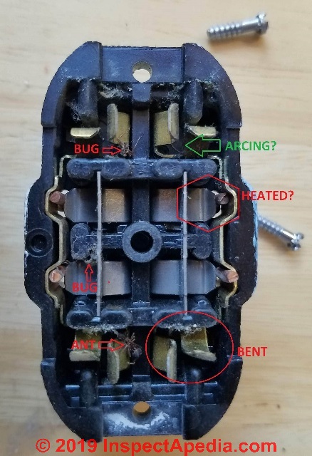
In 2019 we disassembled and photographed a push-in type backwire recptacle from a 1960-built home in northern Minnesota.
That receptacle, a backwire-only product, showed the best contact area and generally best construction (Opinion from Aronstein that I share) that we've seen in these devices.
In our first backwire receptacle connector photo above, notice that the contact spring that forces the wire against the contact plate has cut deeply into the wire and that there is - at least to the eye, good contact between the rounded wire surface and the rounded surface of the contact plate.
More about this detail is
at RECEPTACLE WIRE-TO-CONNECTOR CONTACT AREA SIZES
and
at WIRE-TO-CONNECTOR FORCE COMPARISONS
Above: an electrical receptacle retrieved from a Two Harbors Minnesota home wired in 1961.
It's as if the manufacturers originally made heavier-duty, better-designed devices that, perhaps under pressure from foreign competition, just got thinner, and weaker and ... in my opinion, cheaper - and that performed poorly in comparison.
The 1960s device had thicker copper and it used a rounded contact plate against which the locking spring pushed the wire, giving more contact area as long as the wire was somewhat straight along its length than do the flat contact plate, weak spring, thin copper modern versions of this device.
This receptacle served without failure in active use from 1960 until about 2015 when I removed it in response to a complaint that its grip on the family's vacuum cleaner wall plug was "loose".
Indeed one of the spring contacts had got bent. Not bad after 55 years of service.
Inside I could not see certain evidence of arcing, burning, overheating - at least not with the low-power microscope. There were a few dead insect bodies and dust and debris inside the receptacle from fifty years of service.
Sources of Limitations in Wire-to-Connector Contact Area in Push-in Back-wired Electrical Receptacles and Switches
Our lab photographs below illustrate conditions that may reduce size of the contact area between the electrical wire and the electrical receptacle or switch when a push-in, back-wire type connector is in use.
The factors described here are opinion and have not been peer-reviewed by a professional forensic electrical engineer or other industry experts. Use our page bottom CONTACT link or the comments box to offer suggestions or critique.
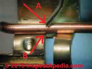
The photograph above illustrates the two intended contact areas between the push-in backwire electrical connector and a #14 copper wire: the contact spring (A in the photo) and the contact plate against which the spring pushes the wire (B in the photo).
Effects of Curved Electrical Wires on Push-In Connector Contact Area in an Electrical Receptacle
At above left is a typical, relatively-straight #14 new copper wire pushed into the spring-connector of a push-in back-wire electrical receptacle connector.
You'll notice that the wire at above-left is not perfectly straight. Some contact between wire and contact plate may be lost at arrow A.
Even when trying to keep the wire straight some bending may occur from handling, during insertion into the electrical device, or near the end when the wire was cut to the proper insertion length - arrow B in the photo above.
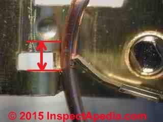
Above is a curved #14 copper wire illustrating the reduction in contact between the wire and the contact plate against which the push-in wire connector spring is exerting force.
Click to enlarge the photo and you'll see that the wire is in contact with the connector plate over about the wire length indicated by the red lines and double-headed arrow.
Curved wire ends may be more likely to occur in old-work, re-wiring, in electrical outlet or switch replacement and similar situations, particularly if the wire being inserted was previously connected by having been bent or curved around the shaft of the screw of an electrical receptacle switch that is being replaced.
The width of the contact plate surface is about 11mm (see the red scale). I estimate that the wire is in contact with the contact plate (ignoring any effects of the cut-out opening) over about 2mm. of that distance.
Additional wire-to-connector effects from notches, abrasion or damage to an older wire are not depicted here: I was using new #14 wire.
Effects of the Leaf Spring Force & Edge Profile on Push-In Connector Contact Area in an Electrical Receptacle
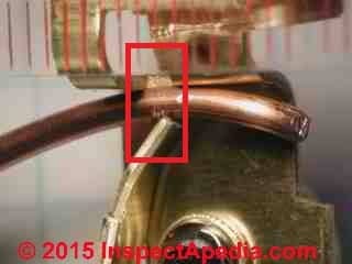
Above at left the photo shows a typical contact point between the notched end of the spring and the copper wire in a push-in backwire connector in an electrical receptacle.
The rounded notch appears to be designed both to increase the wire-to-spring contact area and perhaps to improve the cut or notch formed in the wire by the spring pressure - an effect that would probably improve the resistance against wire withdrawal as well as the wire-to-connector contact.
The notch cut by the spring in the copper wire seems to be increased if the wire is rotated at all during installation or when the receptacle is pushed back into the electrical box.
Above at right is a close-up of the wire notch I'm discussing. You can see that notch increases the actual contact between spring and wire includes more than the mere sharp edge of the spring as it permits contact between the back side of the spring (red arrow) as well as the face or end of the spring (green arrow).
Incidentally we note that the cut-out area of the contact plate (blue arrow) might reduce the contact surface between the wire and the contact plate against which the spring pushes the wire.
Variations in Wire-to-Connector Contact Area on Three Electrical Receptacle Connector Types
The article cited just below compares the approximate size of contact areas between an electrical wire and the connector surfaces in an electrical receptacle across three different connector designs:
- Push-in back-wired electrical receptacles
- Binding head screw connector on electrical receptacles
- Insert-in screw-clamp type back wired or side-wired electrical receptacles
This article concludes that
On an electrical receptacle or switch the binding head screw wire contact area offers about four times the contact surface as a perfectly-made push-in backwired receptacle or switch connection, and if the wire is bent in a push-in connection, the binding head screw offers nearly ten times the contact area as the push-in device.
Please see RECEPTACLE WIRE-TO-CONNECTOR CONTACT AREA SIZES - separate article - for details.
Research on Backwired Electrical Connector Overheating, Failures, Fires

- Aronstein, Jess,[Personal communication, J.A. to the editor (Daniel Friedman)], 25 October 2015. Dr. Jess Aronstein, protune@aol.com is a research consultant and an electrical engineer in Schenectady, NY.
Dr. Aronstein provides forensic engineering services and independent laboratory testing for various agencies. Dr. Aronstein has published widely on and has designed and conducted tests on aluminum wiring failures, Federal Pacific Stab-Lok electrical equipment, and numerous electrical products and hazards.
See ALUMINUM WIRING BIBLIOGRAPHY and FPE HAZARD ARTICLES, STUDIES
and also BACK-WIRED ELECTRICAL DEVICES for examples. - Aronstein, J. (1993), “Evaluation of Receptacle Connections and Contacts,” Proc. 39th IEEE Holm Conf. on Electrical Contacts, IEEE, pp. 253–260.
- Aronstein, J. (1983), “Fire Due to Overheating Aluminum-Wired Branch Circuit Connections,”
Wright Malta Corp., Ballston Spa, NY. - Aronstein, J. (1977), “Investigation of Fire Hazards in Field Samples of Aluminum-Wired Devices,” Wright Malta Corp., Ballston Spa, NY.
- Ashizawa, K. and Omata, K. (1997), “Property of Ignition Mechanism Caused by Thermal Degradation on Plug,” Abstracts of Annual Meeting of JAFSE, Paper C-22, pp. 386–389.
- RECEPTACLE WIRE-TO-CONNECTOR CONTACT AREA SIZES - measurements & calculations of the contact area between an electrical wire and the connecting device on an electrical receptacle or switch explain differences between push-in type backwire connectors, compression plate connectors, and binding head screw connectors, all of which are found on many electrical receptacles and switches.
- Babrauskas, Vytenis. "Electrical fires." In SFPE handbook of fire protection engineering, pp. 662-704. Springer, New York, NY, 2016.
Abstract:
An electrical fire is generally understood to be a fire that is caused by the flow of an electric current or by a discharge of static electricity.
It is not defined as a fire involving an electrical device or appliance. For example, a fire on an electric range that occurs due to overheating and ignition of the oil in a deep-fry pan is not classed as an electrical fire, even though it involves an electrical appliance.
Conversely, an electrical device or appliance is not always needed for an electrical fire to occur. Lightning-caused fires are a form of electrical fires and these can ignite, for example, a dry bush, which is not an electrical device. - Babrauskas, V. (2013), “Arc Breakdown in Air Over Very Small Gap Distances,” Interflam 2013 – Proc. Thirteenth Intl. Conference, Interscience Communications Ltd., London.
- Babrauskas, V. Y. T. E. N. I. S. "Research on electrical fires: the state of the art." Fire Safety Science 9 (2008): 3-18.
- Babrauskas, V. (2006), “The Principles of Electrical Fires,” ISFI 2006 – Proceedings of the 2nd International Symposium on Fire Investigation Science and Technology, National Association of Fire Investigators.
- Babrauskas, V. (2004), “Arc Beads from Fires: Can ‘Cause’ Beads be Distinguished from ‘Victim’ Beads by Physical or Chemical Testing?” Journal of Fire Protection Engineering, 14, pp. 125–147.
- Babrauskas, V. (2003), Ignition Handbook, Fire Science Publishers, Issaquah, WA.
- Babrauskas, V., HOW DO ELECTRICAL WIRING FAULTS LEAD TO STRUCTURE IGNITIONS? [PDF] pp. 39-51 in Proc. Fire and Materials 2001 Conf., Interscience Communications Ltd., London (2001).
Abstract & Introduction Excerpts:
A sizable fraction of ignitions of structures are due to electrical faults associated with wiring or with wiring devices. Surprisingly, the modes in which electrical faults progress to ignitions of structure have not been extensively studied.
This paper reviews the known, published information on this topic and then to point out areas where further research is needed.
The focus is solely on single-phase, 120/240 V distribution systems. It is concluded that systematic research has been inordinately scarce on this topic, and that much of the research that does exists is only available in Japanese.
Background The latest statistics of the National Fire Protection Association [1], available for 1993 ñ 1997 are that 41,200 home structure fires per year are attributed to ëelectrical distribution.í These electrical distribution fires account for 336 civilian deaths, 1446 civilian injuries, and $643.9 million in direct property damage per year.
Ontario Hydro (Oda 1978) conducted a series of tests using duplex outlets wired with aluminum wire and previously exposed to a modest overload of 27 A. The outlets were cycled using a 15 A load applied for 3.5 h, then off for 0.5 h.
A mockup up stud space was built, including thermal insulation inside the cavity and combustibles placed at the face. No male plug was used, the current being drawn by a daisy-chain connection. The results are summarized in Table 2.

Most cases of external heating involve the wire or wiring device as 'victim' of fire and not as the initiator of fire.
But some situations do exist where external heating of wiring serves as the initiating event. In many cases, arcing occurs after sufficient overheating. - Benfer, Matthew E., and Daniel T. Gottuk, DEVELOPMENT AND ANALYSIS OF ELECTRICAL
RECEPTACLE FIRES [PDF] Fire Science and Engineering, a research report submitted to the U.S. Department of Justice. Matthew E. Benfer and Daniel T. Gottuk, Hughes Associates, Inc. 3610 Commerce Drive, Suite 817 Baltimore, MD 21227 Ph. 410-737-8677 FAX 410-737-8688 www.haifire.com September 12, 2013, retrieved 2018/08/09, original source: https://www.ncjrs.gov/pdffiles1/nij/grants/243828.pdf
Abstract:
Laboratory testing evaluated the impact of a wide range of variables on the formation of overheating connections in residential duplex receptacles. Two types of receptacle configurations have been evaluated:
1) those focused on terminal connections and
2) those focused on plug connections.
Testing included 528 receptacle trials, 408 trials with various terminal connections and 120 trials with various plug connections. Thirteen pre-fabricated wall assemblies of 36 receptacles were placed in 8 compartment fire tests and 5 furnace fire tests.
The variables evaluated in the fire exposure testing included: the receptacle material, materials of the receptacle faceplate and box, terminal torque, and energized state of the receptacle.
A portion of the receptacles in the fire exposure testing had overheated connections that were created in the laboratory testing. These receptacles were used to assess whether evidence of overheating would persist after a fire exposure.
All receptacles were documented for damage to the receptacle, faceplate, and outlet box including any arcing, overheating, and/or melting. The results of laboratory testing indicate that only the loosest connections tend to form significant overheated connections irrespective of other variables, such as receptacle materials and installation.
Forensic signatures of overheating have been identified and have been found to persist even after external fire exposure. In addition, locations of arcing within receptacles as a result of fire exposures were identified and characterized.
The location of arcing is primarily dependent on the duration and intensity of the fire exposure, as well as the construction and materials of the receptacle, outlet box, and faceplate. The presence of characteristic indicators of arcing and melting were analyzed.
Excerpt:
1.1.3.4 Back wired Push-in Connections The fire hazards of receptacles employing back wired push-in terminals have also been the subject of much debate in the literature.
Earlier studies had shown that these connections are susceptible to overheating, and many failed the UL 498 [1986] temperature test requirements for receptacles after as little as one removal and reinstallation of a back-wired conductor [Aronstein, 1993], or even after being exposed to a year of normal cyclic loading using 15A and 20A currents [Biss, 1989].
Oda [1978] also found that back-wired push-in receptacles were more likely to ignite proximate materials than side-wired receptacles. These and other studies prompted changes to the 11th edition of UL 498 [1986] for testing requirements for back-wired receptacles, yet there has been no subsequent study to determine any consequent improvements [Babrauskas, 2003]. - Biss, A.A. (1989), “Evaluation of Design and Operating Characteristics of 15 Ampere 125 Volt Receptacle Outlets,” Consumer Product Safety Commission, Washington, D.C.
- Ferrino-McAllister, J. L., Richard J. Roby, and J. A. Milke. "Heating at electrical contacts: Characterizing the effects of torque, contact area, and movement on the temperature of residential receptacles." Fire technology 42, no. 1 (2006): 49-74.
Abstract:
Testing was performed using 120 volt, 15-amp receptacles and copper wire to determine the effect of torque and wire contact area on temperature elevation at receptacle screw terminals. Torque was varied on both the hot and neutral terminals from 0 to 12 in-lbs, and the apparent wire contact at the screw terminal was varied by 1/8″ and 5/8″.
There was no significant difference in temperature when changing apparent wire contact. Increased temperatures were observed with reduced torque, however, they were not significant enough to initiate a glowing connection, nor high enough to cause rapid oxidation.
Further testing showed that movement of a loose connection was necessary to cause significantly high temperature changes, arcing and sparking, rapid oxidation, and in some cases, glowing connections. - Oda, S. J., Progress Report of Fire Initiation Potential of Failing Electrical Receptacles (Report 78-92-K), Ontario Hydro, Toronto (1978).
- Zhou, Xin, and Thomas Schoepf. "Detection and formation process of overheated electrical joints due to faulty connections." (2012): 288-295.
Abstract:
Overheated electrical joints due to faulty connections are often precursors of electric fires, arc faults and arc flash in electrical systems. NEMA procedures call for visual inspection and re-torque on a regular base. Various technologies have been developed for the detection and mitigation of overheated connections. As of today there is no cost effective technology available to monitor and detect overheated electrical joints in electrical distribution equipment.
This paper reviews different technologies developed to monitor and detect overheated electrical connections. Results of recent feasibility investigation on overheated connection detection employing acoustic sensing technology are introduced. Furthermore, investigations on the formation mechanism and behavior characteristics of faulty connection induced overheated electrical joints at different current levels are discussed.
The results demonstrate that overcurrent has a major impact on the overheated electrical joint formation process. Collapsing of overheated contact spots can be observed during the thermal test cycle. It is an indication of softening or even melting of the existing contact spot and formation of a new contact spot. - Zhou, Xin, and Thomas Schoepf. "Characteristics of overheated electrical joints due to loose connection." In Electrical Contacts (Holm), 2011 IEEE 57th Holm Conference on, pp. 1-7. IEEE, 2011.
Abstract:
Overheated electrical joints due to loose connection are often precursors of electric fires, arc faults, and arc flash in electrical systems. This paper is about the formation mechanism and behavior characteristics of loose connection induced overheated electrical joints. Specific experiments were conducted on busbar joints and systems with currents ranging from 100 A up to 5000 A.
The lead time of the overheated contact formation is significantly impacted by the tightening torque of busbar bolts, the amplitude of current, and the proper sizing of electrical joints. - Also see additional citations atReferences or Citations below
Comparing Clamping Force in Two Electrical Wire-to-Connector Devices: Back-wired Spring-Clip vs. Binding Head Screw
This discussion has moved to WIRE-TO-CONNECTOR FORCE COMPARISONS
There we compare estimates of the connection force exerted by a spring clip wire connector and a binding head screw wire connector. Stronger contact surface force means a more reliable contact and better connector performance.
Failures in Back-Wired Electrical Receptacles Illustrate the Failure Condition & are Attributed to Low Contact Force
This topic has moved to BACKWIRED RECEPTACLE FAILURE PHOTOS
In that article we quote:
Low contact force between the wire and the receptacle connector where spring-type push-in backwired terminals are used on receptacles is probably the most significant reason that these connections can be expected to deteriorate over many years.
...
Reader Comments, Questions & Answers About The Article Above
Below you will find questions and answers previously posted on this page at its page bottom reader comment box.
Reader Q&A - also see RECOMMENDED ARTICLES & FAQs
On 2021-02-23 - by (mod) -
@Anonymous, It's possible that as with Jeff I don't understand your question correctly.
But it seems to me there's no requirement for an electrical receptacle to have both side screw and back wire connectors. I have certainly encountered products that only could be back wired.
However as we warn you in this article series, pushing back wire connections are considerably less reliable and therefore possibly Less safe than using a screw terminal type connector.
It's worth noting that there are some back wired receptacles that use a clamp to secure the wire and the clamp is intern secured by a screw. That's a very good connection.
The connection that I am referring to as unreliable is a push-in-only connection that relies on a simple and thin spring clip inside the receptacle to make the connection. Details are in the article above
Mini electrical receptacles offer both types of connections, that is a push-in-only spring clip backstab connection that I do not recommend and a side terminal screw connection that's perfectly fine.
On 2021-02-23 by Anonymous
Why would it be necessary to have screw side mount connections and backstab hole connections to a single Outlet?
On 2021-02-23 - by (mod) -
@Jeff, apologies but I don't understand the question. If the previous receptacle had electrical connections bringing power to it as well as feeding power to a downstream receptacle you would have to continue those connections or the downstream receptacle would be dead.
On 2021-02-23 by Jeff
I remove a outlet from the kitchen wall above the counter not near a water source but still in the kitchen. It had side and back wiring connected to it. I put a new one in and repeated the process as it was previously wired but then I read is something about that not being correct. What do I do with the other two wires that went into the back
On 2020-04-12 - by (mod) -
Barbara
In my opinion your electrical wiring of receptacles is improper, unsafe, unreliable, violates the manufacturer's instructions, warranty, and the electrical code.
Using a side-screw connection, including the really-easy back-insert connection that clamps the wire by tightening the side screw, is a superior connection and, properly performed, follows the manufacturer's instructions.
I can't assess the immediate danger; certainly if the circuit is off or not in use the danger is minimized.
On 2020-04-12 by Barbara
Plugs kept falling out of our old receptacles, so my husband replaced them using the backstab option on the new receptacles. The problem is that whenever he found 12 gauge wire, he forced it into the 14 gauge backstab holes. Is this of any immediate danger, or can it be fixed in due time?
He plans to redo them all using the side screw connections (which are smooth under the heads, not binding heads). If he can’t pull out the 12 gauge wires from the backstab holes, we will cut the wires and buy new receptacles
On 2019-09-21 by (mod) - ungrounded receptacle wiring in 1940s home
Stephanie
In the 1940s when your home was built it was common to run two wire circuits - Hot, Neutral, but no grounding conductor.
TO install a GFCI or an AFCI AND to have it work in all situations including the in-device testing you'd want a circuit that included a grounding conductor.
Still you can install a GFCI on a 2 wire circuit
BUT
1. it cannot be tested reliably using its internal tester
2. it is technically improper to install an electrical receptacle that has a third hole for the grounding prong on wall plugs but is wired without an electrical ground
I might go ahead and install the GFCI anyhow as a safety improvement, but I'd label the receptacle with a NO GROUND warning.
The existing wire may be ok to use or not - no one with any experience would nor should pretend she can tell you the safety or condition of the electrical wiring in a 1940 circuit by simply looking at a couple of inches of two wires in one location.
On 2019-09-21 by Stephanie N.
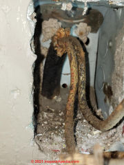
I have a kitchen outlet in my 1940's house that sparked when I plugged something in. It is located within 6' of the sink and I want to switch it out for a combo GFCI/ACFCI outlet. When I turn off the breaker, my NCVT has detected some low voltage that seems to decrease with time. Today the NCVT stayed green so I pulled the outlet out and found two wires coming from one black patterned sheath.
The 2 wires appear to be covered in cloth or paper that is held in place with a very thin wire(?) wrapped along its length. One wire appears to be copper and the other has a silver sheen -possible tinned copper or aluminum. The outlet states to use only 12-14 gauge copper wire with it.
My questions are 1) what kind of wire is this and is it safe,
2) is it normal to only have 2 wires instead of 4 at an outlet, and
3) is it okay to replace the outlet with a Leviton GFCI/AFCI outlet?
On 2018-11-08 - by (mod) -
Anon:
Not exactly, Anon. There are some back-wire electrical receptacles that use a screw-activated clamp that makes excellent wire contact. We discuss that advice in the article above on this page. I'll re-post a photo below.
IMAGE LOST by older version of Clark Van Oyen’s Comments Box code - now fixed. Please re-post the image if you can. Sorry. Mod.
PS:
I (editor) accidentally lost Anon's comment to which the below was a reply:
On 2018-11-07 by Anonymous - so we should only ever use the side screws to connect wires to a receptacle or switch?
So the bottom line is, only use the screws.
...
Continue reading at RECEPTACLE WIRE-TO-CONNECTOR CONTACT AREA SIZES for a discussion of the areas of wire-to-receptacle contacts on electrical receptacles., or select a topic from the closely-related articles below, or see the complete ARTICLE INDEX.
Or see these
Recommended Articles
- BACK-WIRED ELECTRICAL DEVICES - home
- BACKWIRED RECEPTACLE FAILURE PHOTOS
- BACKWIRED RECEPTACLE FAILURE REPORT
- BACK-WIRING FAQs for RECPTACLES & SWITCHES
- LIGHT SWITCH WIRING DETAILS
- ELECTRICAL OUTLET, HOW TO ADD & WIRE - home - for general wiring procedures, connections & advice for connecting electrical receptacles.
- RECEPTACLE WIRE-TO-CONNECTOR CONTACT AREA SIZES
- WIRE-TO-CONNECTOR FORCE COMPARISONS
- WIRE-TO-CONNECTOR PERFORMANCE SUMMARY
Suggested citation for this web page
BACK-WIRED ELECTRICAL DEVICES at InspectApedia.com - online encyclopedia of building & environmental inspection, testing, diagnosis, repair, & problem prevention advice.
Or see this
INDEX to RELATED ARTICLES: ARTICLE INDEX to ELECTRICAL INSPECTION & TESTING
Or use the SEARCH BOX found below to Ask a Question or Search InspectApedia
Ask a Question or Search InspectApedia
Questions & answers or comments about how to install and wire electrical outlets or receptacles in buildings.
Try the search box just below, or if you prefer, post a question or comment in the Comments box below and we will respond promptly.
Search the InspectApedia website
Note: appearance of your Comment below may be delayed: if your comment contains an image, photograph, web link, or text that looks to the software as if it might be a web link, your posting will appear after it has been approved by a moderator. Apologies for the delay.
Only one image can be added per comment but you can post as many comments, and therefore images, as you like.
You will not receive a notification when a response to your question has been posted.
Please bookmark this page to make it easy for you to check back for our response.
IF above you see "Comment Form is loading comments..." then COMMENT BOX - countable.ca / bawkbox.com IS NOT WORKING.
In any case you are welcome to send an email directly to us at InspectApedia.com at editor@inspectApedia.com
We'll reply to you directly. Please help us help you by noting, in your email, the URL of the InspectApedia page where you wanted to comment.
Citations & References
In addition to any citations in the article above, a full list is available on request.
- [3] NFPA - the National Fire Protection Association can be found online at www.nfpa.org
- [4] The NEC National Electrical Code (ISBN 978-0877657903) - NFPA might provide Online Access but you'll need to sign in as a professional or as a visitor)
- US NEC Free Access: See up.codes at this link: https://up.codes/code/nfpa-70-national-electrical-code-2020
- "Evaluating Wiring in Older Minnesota Homes," Agricultural Extension Service, University of Minnesota, St. Paul, Minnesota 55108.
- In addition to citations & references found in this article, see the research citations given at the end of the related articles found at our suggested
CONTINUE READING or RECOMMENDED ARTICLES.
- Carson, Dunlop & Associates Ltd., 120 Carlton Street Suite 407, Toronto ON M5A 4K2. Tel: (416) 964-9415 1-800-268-7070 Email: info@carsondunlop.com. Alan Carson is a past president of ASHI, the American Society of Home Inspectors.
Thanks to Alan Carson and Bob Dunlop, for permission for InspectAPedia to use text excerpts from The HOME REFERENCE BOOK - the Encyclopedia of Homes and to use illustrations from The ILLUSTRATED HOME .
Carson Dunlop Associates provides extensive home inspection education and report writing material. In gratitude we provide links to tsome Carson Dunlop Associates products and services.


