
 Electrical Receptacle Wiring in Parallel vs Daisy-Chained
How to wire up a receptacle or "outlet" - two options
What is the difference between series & parallel
in electrical circuits?
- POST a QUESTION or COMMENT about how to install and wire electrical outlets or receptacles in buildings.
How to wire up an electrical receptacle in one of two methods: parallel or "daisy-chained" and the difference between the two.
Here we compare wiring an electrical receptacle wired "daisy chained" from one to another (the most-common practice) with wiring receptacles in parallel on an electrical circuit.
Wiring in parallel gives greater reliability to the devices on the electrical circuit, but larger electrical boxes and more wiring connections are required.
We also explain the difference between a series and a parallel device electrical circuit, and we note that laypeople may refer to daisy-chained electrical receptacles on a circuit as "in series" even though technically that's not correct.
In this article series we illustrate basic connections seen in the field for the black, white neutral or grounded conductor), and ground wire when hooking up an electrical receptacle (wall plug or "outlet").
Watch out: mis-wired electrical receptacles are dangerous. Electrical wiring should be performed by a licensed, trained electrician and should comply with the National Electrical Code and local regulations. This article series describes how to choose, locate, and wire an electrical receptacle in a home.
InspectAPedia tolerates no conflicts of interest. We have no relationship with advertisers, products, or services discussed at this website.
- Daniel Friedman, Publisher/Editor/Author - See WHO ARE WE?
Wiring Daisy-Chained vs. Pigtailed Parallel-Wired Receptacles
[Click to enlarge any image]
What's the difference between wiring electrical receptacles in a daisy-chain versus wiring them in parallel?
Why does it matter?
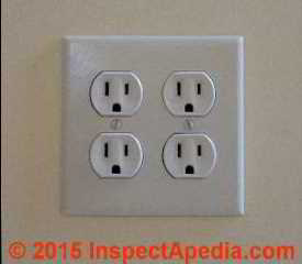
It matters because if any connection fails in electrical receptacles wired in a "daisy chain" as drawn above and as shown in our photo below, all of the downstream electrical receptacles will also lose power.
Definition of daisy-chained ("in-series") electrical wiring
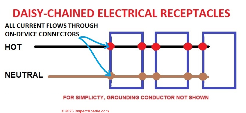
In an electrical circuit in which receptacles are wired daisy-chained together (a practice some electricians call in series) (illustrated above), all of the receptacles are connected "end to end" and pairs of terminals on each receptacle are used to carry current from each device on to the next one in the circuit.
All of the current flows through the copper terminal screws and strips or wire clamps each device, in this case an electrical receptacle, in the circuit.
That is, current flows through the first electrical receptacle connectors on the first device in the circuit then on to and through the second receptacle or device, then on to and through the third in series, etc.
If any electrical connection or device in this a series is interrupted (a broken wire, a loose screw, a failed push-in wire connection) then receptacles wired after or "down-stream" from that point will lose power - they wont' work. In most buildings and certainly in homes, electrical receptacles are wired in series.
Really? Well not quite. Technically, electrical devices that were wired "in series" electrically would mean that all of the current flowing in the circuit flows through all of the devices in the circuit.
Here, by electrical receptacles wired "in series" electricians mean that they're wiring electrical receptacles such that the connectors (screw or push-in terminals) for each receptacle are used to feed the next electrical receptacle in the series.
Definition of in-parallel electrical wiring
In an electrical circuit in which receptacles are wired in parallel (illustrated below), the receptacles are connected along multiple paths such that if any of the receptacles fails - a loose wire, screw or other component, other receptacles on the circuit are unaffected. In a parallel circuit, the current flow is divided so that only part of it flows through each device.

Details of these two wiring methods are given below.
These two wiring methods differ not only in the effect of a break or failure of a connector at an individual receptacle but also in their electrical properties.
Formal Definitions of "Series" & "Parallel" Circuit Wiring
In a series circuit, the current that flows through each of the components is the same, and the voltage across the circuit is the sum of the individual voltage drops across each component. (Resnick 1966)
A series circuit comprises a path along which the whole current flows through each component. - Encyclopedia Britannica
in a parallel circuit, the voltage across each of the components is the same, and the total current is the sum of the currents flowing through each component. (Resnick 1966)
A parallel circuit comprises branches so that the current divides and only part of it flows through any branch.
The voltage, or potential difference, across each branch of a parallel circuit is the same, but the currents may vary. - Encyclopedia Britannica
Daisy Chain-Wired Receptacles
 In our photograph of the back of an older electrical receptacle here, (synonyms for "electrical receptacle" used by normal people include "outlet" or "wall plug"), this back-wired receptacle illustrates wiring electrical receptacles in series or "daisy-chained".
The pair of white wires in the upper portion of this photo are are marked as NEUTRAL IN and NEUTRAL OUT.
White wires are to be connected to the silver terminals or screws or to the terminals marked "WHITE" or "NEUTRAL"
- One of these white wires brings the neutral wire of the circuit in to the electrical box and connects to the receptacle.
- The second white wire connects the circuit neutral onwards to the next receptacle downstream from this one.
The pair of black wires in the lower photo are marked HOT IN and HOT OUT.
Black wires are connected to the brass or gold colored terminals or screw or to the terminals marked "Black" or "Hot".
- One of these black wires brings the circuit hot or "live" wire in to the electrical box where it connects to either of the receptacle's "hot" or "black" terminals.
- The second black wire connects to the receptacle's second "hot" or "black" terminal and carries the circuit's hot or live wire onwards to the next receptacle or device that is downstream from this one.
Technical note: Having nothing to do with daisy-chaining or not, back-wiring, as shown in our photo above, is an accepted wiring practice, though on newer receptacles and in my opinion better workmanship jobs you will see the wire connections made at screws or screw clamps more often than in simple push-in backwired connections.
Watch out: we do not recommend back-wiring receptacles that use only a spring-clip type wire connector. Those connections are not in our opinion reliable nor safe.
Details are at BACK-WIRED ELECTRICAL DEVICES
Properties of "Daisy-Chained" electrical receptacles
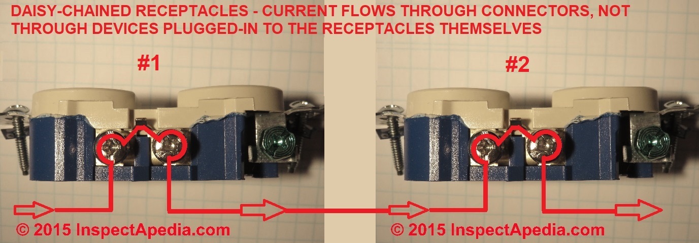
As we illustrate with the red "wire" in our photo below, electrical power flows from the incoming "hot" wire at Receptacle #1 through the receptacle internal parts (the brass screws and copper connector strap) and onwards to the brass screws and copper connector strap of receptacle #2.
Should an individual electrical receptacle (or "outlet") fail or lose one of its connections such that it loses power, all of the electrical receptacles on the downstream side of the circuit will also lose power.
Note that power to the downstream daisy-chained or "in series-wired" receptacles flows through wires and connectors and not through devices that are plugged-into the receptacles themselves.
Most electricians wire electrical receptacles in this daisy-chain series.
Some electricians call the wiring method above "wiring in series" though technically that is not correct. The four wall plug connectors on the two duplex receptacles shown above are actually wired in parallel. Each of the four wall plug connectors receives power independently from all of the others.
However IF any of the wire connections at receptacle #1 come loose or burn-up so that the connection no longer works, receptacle #2 will no longer receive electrical power.
That's why some electricians wire receptacles in the more-complex parallel wiring shown below.
Ground connections on daisy-chained receptacles:
Notice that only the hot and neutral wires are daisy-chained through the receptacle's screws and copper strap.
The electrical ground connection for the receptacle is connected to a the circuit ground single ground screw on the device, and of course if a metal electrical box is used, an additional ground-wire is connected from the circuit ground to the metal box as well.
Wire Electrical Receptacles on a Single Circuit In Parallel
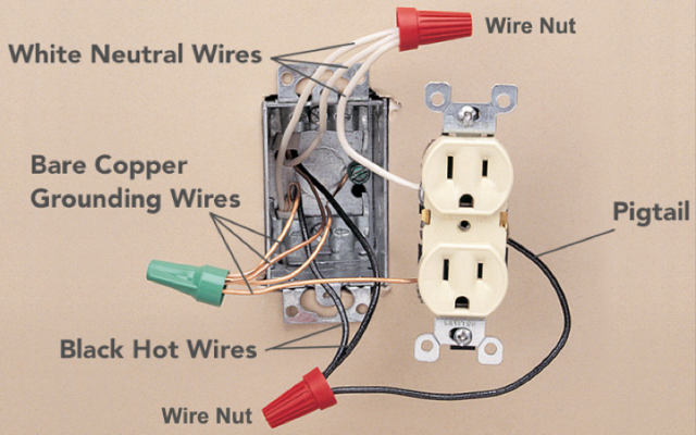 Photo: this reader-provided illustration shows how an electrical receptacle might be wired in parallel to the circuit. Using twist-on connectors and pigtail wires the receptacle's neutral and hot terminals are connected to the circuits hot and neutral wires.
In some jurisdictions electricians prefer to not "daisy chain" receptacles in the same box together by using the second pair of screws on each one.
Rather the circuit enters the box and using twist-on connectors, short pig-tail wires are connected to each receptacle at the proper screws. This approach requires a larger electrical box as it will contain more connections, connectors, and so needs more room.
Properties of Electrical Receptacle Circuit Wired in Parallel
When wired in parallel as shown in the photo above, should an individual electrical receptacle (or "outlet") fail or lose one of its connections such that it loses power, the rest of the circuit remains "live".
Electrical power is thus retained at all of the other receptacles on the circuit.
Wiring Connections for Receptacles in Parallel
You'll see three wires at teach twist on connector:
Black: (3 wires) hot in, hot out, hot pigtail to the receptacle
- The black or "hot" wire from the circuit entering the electrical box goes to a twist-on connector or "wire nut"
- The black or "hot" wire leaving the electrical box to go onwards to the next electrical box (and devices) downstream goes to the same twist-on connector.
- The third short black "hot" wire is a "pigtail" that connects from the twist-on connector to the receptacle "hot" or "black" terminal
White: (3 wires) neutral in, neutral out, neutral pigtail to the receptacle
- The white or "neutral" wire from the circuit entering the electrical box goes to a twist-on connector or "wire nut"
- The white or "neutral" wire leaving the electrical box to go onwards to the next electrical box (and devices) downstream goes to the same twist-on connector.
- The third short The white or "neutral" wire is a "pigtail" that connects from the twist-on connector to the receptacle neutral terminal
Ground wires: (4 bare copper wires) ground in, ground out, ground to receptacle, and a ground to the metal electrical box (if the box is metal rather than plastic).
At BACKWIRED RECEPTACLE FAILURE REPORT we illustrate a use of these two wiring practices in which the contributor is replacing a back-wired daisy-chained receptacle with a new receptacle wired in parallel on the circuit.
Check the Size of the Electrical Box When Adding Pigtails
 Watch out: when converting from device-wired to a parallel-wired electrical circuit in a string of receptacles, you may not be permitted use this pigtailing method unless the electrical box size is of sufficient cubic inches to contain the additional wires and connectors.
In the illustration of parallel wiring of an electrical receptacle shown above we have
- 3 neutral wires - count as 3 #14 conductors
- 3 hot wires - count as 3 #14 conductors
- 4 ground wires - count as 1 #14 conductor; all of the ground wires are counted as equivalent to 1 of the largest conductors present in the box
- 3 twist-on connectors - not counted when calculating the required box size
- 1 electrical receptacle - not counted when calculating the required box size
all of which have to jam into the electrical box. Using NEC box sizing rules that's a total of 7 #14 wires.
[Reader Don says this is wrong but that the total number of "wires" remains at 7 for "different reasons" - see his comment below on this page]
Assuming the circuit we show is a 15A circuit using #14 wire, the U.S. NEC requires 2 cubic inches per conductor. The box must be (2cu.in. x 7 conductor) 14 cubic inches or larger.
Tables in the NEC and given also at ELECTRICAL JUNCTION BOX TYPES tell us that for this wiring we can use a box of these dimensions
- 3 x 2 x 3 1/2" Device Box (18 cubic inches)
- 4 x 2 1/2 x 2 1/8" Device Box (18 cubic inches)
- or larger
The National Electrical Code Article 314 contains complete details and tables of electrical box sizes in dimensions and cubic inches and should be consulted for complete accuracy because the actual size of the box required, in cubic inches, depends on the number of wires that will be within that enclosure.
If you need more space than the present box allows, it may be possible to expand the existing box by adding a "side car" extension described in the article cited just above and illustrated in our photo.
That's a heck of a lot easier than pulling the whole existing box and wall apart to replace it with a deeper or wider box.
Watch for Line and Load Terminal Markings
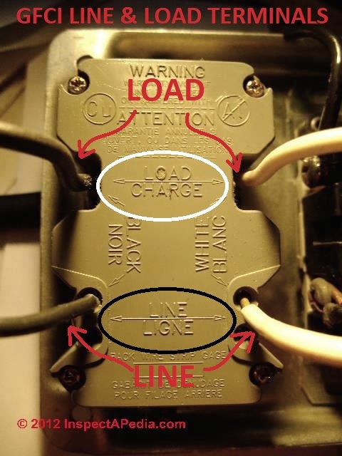
Watch out: some devices such as AFCI and GFCI receptacles will have LINE and LOAD markings on the receptacle side or back.
[Click to enlarge any image]
The photo shows a ground fault circuit-interrupter receptacle that has been back-wired using push-in connectors, and that is wired in the "daisy chain" or "in series" method described above. Devices connected downstream from this one are wired out of the LOAD terminals as I will explain:
In my GFCI photo I have circled in white and black the embossed markings on the receptacle back that indicate "LOAD" and "LINE" terminals.
The incoming or LINE white (neutral) and black (hot) wires are in the bottom of the photo.
The outgoing or downstream or LOAD white (neutral) and black (hot) wires are in the top area of the photo.
Details are at WHICH WIRES GO to LINE or LOAD CONNECTIONS?
Watch out: If you do not make these connections properly power will still be delivered to the GFCI receptacle but it will not provide proper GFCI protection for downstream devices and/or its internal test and reset buttons will not function.
...
Reader Comments, Questions & Answers About The Article Above
Below you will find questions and answers previously posted on this page at its page bottom reader comment box.
Reader Q&A - also see RECOMMENDED ARTICLES & FAQs
On 2023-01-01 by InspectApedia Publisher (mod)
@Anonymous,
Thank you for commenting;
We agree, that what you say is technically quite correct.
Please keep in mind that in many InspectApedia articles we make a point of including not only the proper terms and proper spelling of terms but also other forms of terms and words that we find readers frequently use in searching for help.
Our object is to both to provide technically accurate and safe information and also to be sure that people who themselves are not experts and who may use the "wrong terms" such as "how to wire up electrical outlets in series" can in fact find a valid answer to their question.
If you have additional suggestions about how to meet the objectives of accuracy, safety, and accessibility, we'd welcome them.
Please CLEAR YOUR BROWSWER CACHE and then REFRESH THIS PAGE to a look at the updated page.
On 2023-01-01 by Anonymous
@InspectApedia-911,
Receps are NEVER wired in series. NEVER!
On 2023-01-01 by InspectApedia Publisher (mod) - Electrical receptacles are "never wired in series"
@John,
First, we are sorry that you found our description of two methods of electrical wiring - in parallel or daisy chaining (loosely-referred-to as "in series" by many electricians) upsetting.
Second, we thank you for taking the time to write to suggest you found the terms in the article unclear or mistaken.
We agree that technically what is described as "wiring in series" means technically that current flows through all of the devices in the circuit
and "wiring in parallel" means that it does not.
And there has been considerable discussion among electricians for decades about this distinction when wiring electrical receptacles.
Wiring receptacles "in series" or "daisy-chaining" as we describe it in this article series, as used here means that a receptacle "B" that is electrically downstream or wired "after" receptacle "A" is fed through the terminals right on receptacle A and onwards to B.
You're right to want writing about electrical wiring to be safe and accurate and technically-correct. We're also faced with the challenge of needing to use popular terms that less-expert people than you frequently use in web searching - because we want people to find the right, safe answer even when they don't know the words that you would require them to use.
Simple Schematic Explains Wiring in Series vs. in Parallel

In a series circuit (above left) all of the devices or components are wired "end to end" so that there is only ONE path for the flow of electrical current: through all of the devices in the circuit.
In a parallel circuit (above right) the leads to each component (in our case, electrical receptacles) are connected across each other's leads so that no matter how many receptacles are in the circuit, they all see the same voltage, and there are separate, independent, electrical paths through each receptacle in the circuit.
Daisy-chained electrical receptacles - shown above - is the most-common method of receptacle wiring. In fact those copper strips on the sides of the receptacle, speaking more-precisely, are in effect forming a parallel circuit.
That is, electrical current does not flow through the wall plug connectors and devices that are plugged-in to each receptacle opening on to the next device.
The fact that the daisy-chain or (speaking technically incorrectly) "in series" electrical receptacle wiring method requires fewer connectors and wires than the "parallel" wiring method described next may explain why this is the most-common method of electrical receptacle wiring that we find in homes.
A failure in a single connection of daisy-chained receptacles drops power to everything "downstream"
A shortcoming of the daisy-chain electrical receptacle wiring method is that if receptacle A's connections loosen or become damaged, as often happens over the life of a much-used receptacle, ALL of the receptacles "downstream" from A, meaning B C D etc ALL will drop power.
Advantage of wiring electrical receptacles "in parallel" as electricians use the term
An advantage of the "wiring in parallel" as electricians use that phrase in a less technical sense than your comment,
is that a problem with receptacle "A" will not cause power to drop to the other receptacles on the circuit, because A, B, C, and all other receptacles on the circuit are fed individually by short individual hot and neutral wires pigtailed to the main circuit wiring using twist-on connectors or other approved connectors.
Now John, we appreciate that you took time to write about wording that you found confusing or annoying about electrical wiring popular method names and we invite you to consider the reasons for the two different electrical receptacle wiring methods described in this article series.
We have reviewed and made a few small additions to the article above to make clear that "in series" as used here simply means that the connectors on each device are daisy-chained to the next one in the circuit.
YOU MAY NEED TO CLEAR YOUR BROWSER CACHE to see the updated page.
If you would like to offer, for the benefit of other readers, specific suggestions for making electrical receptacle wiring more clear, more safe, and more-accurate, we'd be glad to consider that help.
Working together makes us smarter. A chat bot would have answered you differently. And it would not, minutes after a nasty comment, have reviewed and edited the article and its illustrations.
On 2023-01-01 by John - it's "daisy chaining" not "wiring in series"
The use of the term series is 100% wrong in this article. Receptacles are NEVER wired in series, as in NEVER. In a series circuit all current must travel through all loads in order to complete the circuit. Also, total voltage of the circuit is divided among the the loads. In other words, if you truly wired 3 receps in series and you plugged in 3 identical TVs (1 in each recep), none of them would work because each would only get 40 volts. Also, all 3 TVs would have be plugged in and turned on for any current to flow so if only 1 or 2 TVs were plugged in or any 1 TV was off, current wouldn't be able to flow. Going in one terminal screw and out the other is parallel wiring and it's commonly known as daisy-chaining. It is NOT series wiring in any way, shape, or form.
On 2022-12-30 by InspectApedia Publisher (mod) - how do I find the bad connection in daisy-chained receptacles?
@Harris Handoko,
If you're sure that power is on at the panel, you want to follow the circuit powering the "dead" receptacles from the panel forward, looking for any electrical junction boxes before the first receptacle in the chain.
If there is none, then go to the first receptacle in the chain that's dead: that's probably where a wire has come loose or burnt-up.
In my OPINION & experience, back-wiring electrical receptacles is generally not reliable - the contact area is often just too small and too-often the contact is loosened or damaged when the receptacle, having been "wired" is pushed back into the electrical box.
Let me know what you find.
And
Watch out: turn power off before working on the circuit, and if you have to turn power on for more testing, remember that if you touch a hot connection you can be shocked or killed.
On 2022-12-30 by Harris Handoko
Hello! I find your website to be very helpful, especially in explaining the part about daisy chain.
I'm currently in this situation:
- A bunch of outlets in the basement room and living room without power.
- No GFCI outlet governing these outlets (at least not to my knowledge).
- There is power coming out of all circuit breakers (measured ~120V on all of them at the panel).
- 3-pronged outlet testers say OPEN HOT on all the dead outlets.
- Outlet wiring configuration: I cracked one open just to see.
2 Black wires shoved onto the back holes on the right side (top and bottom), 2 white wires on the left side, 1 ground exposed wire.
- Voltage sniffer didn't detect any current as far as I can tell. But that circuit breaker which I think controls these bunch of outlets is still ON.
I believe these outlets fit the description of Daisy Chained. Now I'm trying to figure out how to diagnose that loose connection somewhere without paying crazy money for an electrician. Any helpful advice, additional tools I can use?
I should add that the panel is in the laundry room right behind the basement room, and the living room is directly above the basement room. The entrance half-floor landing area leading to the basement and the living room also has a light switch which has no power (light doesn't work).
On 2022-10-19 by InspectApedia-911 (mod) - use of the term "series" is confusing and just furthers the misuse of the term.
@Christopher,
Thank you for the suggestion on making this topic more clear.
We have reviewed and edited the article above with your advice in mind.
On 2022-10-19 by Christopher
I'm with Don, the use of the term "series" is confusing and just furthers the misuse of the term. Series and parallel have clear definitions when it comes to electrical circuits. Power circuits are wired in parallel, full stop.
I understand that the term "series" is common but I think any educational material should explain at the beginning that this is actually a parallel circuit and then use the term daisy-chain throughout.
On 2022-08-08 by InspectApedia-911 (mod) - the phrase "wired in series" is confusing
@Don,
Thanks that's a good suggestion; we'll review and clarify the text.
Of course you're perfectly right that some electrical current flows through the devices (at least when in use) in both series and parallel wiring schematics for electrical receptacles.
Our article above focuses on the practical implications of the two wiring methods, and wants readers to understand those: an interruption in the wiring of a serial-wired receptacle circuit will cause the downstream devices to lose power while in a parallel-wired design that's not the case.
Our choice of words and phrases is made in part to be sure that people who search for "parallel electrical outlet wiring" or "in-series electrical receptacle wiring" will find these pages, this article, and they'll find the discussion familiar.
Thank you for taking the time to comment - it is helpful.
I've added text and illustrations at the top of this page and we'll welcome your further remarks on this or any other information you find at Inspectapedia.com
Working together helps us help others.
Daniel
On 2022-08-07 by Don
I don't think it is a good idea to use the term "series" when describing the difference between wiring receptacles using a pig tail versus wiring receptacles using the screw terminals on a receptacle, as both methods are technically wiring in parallel.
I understand that the article is for the untrained DIY'er, but if the untrained reader takes your series comment and then does some of their own research, they are going to be confused by your choice of words.
Say they take the initiative to Google what is the difference between series and parallel, they are going to be even more confused and more likely to do something wrong when they learn about voltage drop and everything in their supposed series circuit of receptacles having the same current draw.
I am not trying to be a troll and point out the obvious, but just offering a thought about cleaning up the language. If you are a trained electrician, which it sounds like you are, you must know that this terminology is incorrect and misleading.
Anybody who has taken the most basic circuit theory course or even just studied the NEC or their Ugly's book knows that receptacles are never or almost never wired in series with eachother, as you wouldn't be able to deliver 120V to downstream receptacles, due to having a voltage drop across each receptacle that is consuming power along a series connected circuit path like such.
I actually don't think there is any practical use for such a circuit in regards to receptacle wiring, but that is why I stated, "never or almost never" when describing how impractical it would be to do such a thing, just to cover my own butt in case there is something out there that I am unaware of where wiring receptacles in series would be useful.
ANYWAYS, sorry for the long opinion and explanation, but a different choice of words would have given the article a lot more credibility and caused less confusion even for the average DIYer that doesn't touch electric on a day to day basis.
I am a firm believer that it is significantly more difficult to learn a new concept when you first have to unlearn doing something the wrong way or even calling something the wrong thing, so in my opinion, there is no sense in using or giving out the wrong terminology when teaching somebody that is inexperienced and/or just starting to learn about electricity to complete a project themselves.
Just my opinion, but as an electrical engineer and industry professional who has trained many electricians over the course of my 22 year career at my former employer, I am very confident you would be farther ahead using the proper or correct terminology even for the average DIYer.
Like I said, it is just my opinion. The rest of the article was decent in explaining when to use a pig tail versus when you may not have room.
I am not certain if your box fill description was correct, but I would need to look that up to verify if it was and do not have the time for that now, but stating that using a pigtail versus not using one would be best determined by the size of the box and the number of wires entering and exiting the box, as well as the size of the receptacle was a good idea for the untrained DIYer to hear,
so overall the article wasn't terrible, but I would clean up some language most notably the part where you refer to wiring receptacles up in "series" if you wanted my seal of approval, not that, that my seal of approval does anything for you.
On 2021-02-17 by (mod) - a failure in a parallel-wired receptacle doesn't kill power to the downstream devices
@Alex,
In the article above I have included text that explains that the current flows from the incoming hot wire through the copper connector on the. Receptacle, Through its copper strip, and out the downstream or outgoing terminal and Hot wire , and of course the same on the neutral side of the receptacle perhaps I shoot out of illustration or two that make that more evident.
Of course you are right that breaking the or neutral path anywhere in the circuit drops power to the devices downstream.
The distinction between daisy-chained and in-parallel receptacle wiring is that for an in-parallel receptacle system a failure at the receptacle itself doesn't kill the rest of the circuit.
When receptacles are wired in parallel, even if an individual electrical receptacle is damage such that it no longer carries current, the remaining receptacles in the string will have power.
When receptacles are wired in series or "daisy chained" through the receptacle's connectors (hot in, hot out, etc), then if the receptacle is damaged such that current no longer flows through its copper side straps on its hot and neutral sides, then all of the receptacles downstream from this point will also lose power.
I have reviewed and edited the article text to see if I can make it more clear. I appreciate your comment and welcome any further suggestions that help make clear the distinction between "in-series" or "daisy-chained" electrical receptacles and those wired "in parallel".
On 2021-02-16 by Alex - I believe that this article uses the term "series" oddly
I believe that this article uses the term "series" oddly. If the receptacles were truly in series you would have to have something plugged into the 1st receptacle in order to have the 2nd one receive power and you would see a voltage drop in downstream receptacles. For example, you wouldn't get 120 V if you have something plugged in earlier in your series.
When you are saying 'in series' you really just mean that you are using the receptacle as the connector. Inside the receptacle the Line and Load are connected permanently - you don't have to have something plugged in to complete the connection.
This just means that if the receptacle is damaged and the Line/Load connection is severed, then downstream receptacles would no longer get power. It's no different than just disconnecting the Line/Load wires in your box.
At least that's how I understand it. Let me know if I got something wrong here.
This site explains it: https://www.hunker.com/13414120/how-to-wire-electrical-outlets-in-series
On 2021-01-14 by (mod)
Jim:
The underlying concern is crowding and its effects that include both heat and mechanical stress that can actually loosen electrical connections that are jammed into too-small a space.
You may have experienced, as have I, what happens when we try to push too many wires and connectors back into a too-small electrical box and then try to shove in the receptacle or switch: one or more connectors bends and comes loose, either totally loose so as to open the connection, or just slightly loose so as to cause arcing and ultimately overheating.
On 2021-01-14 by Jim
correction: Dan commented that we do count the device
sorry I misspoke naming Dennis; the comment is by Don of Aug 11 below. The question is: do we or do we not count the device in calculating box size?
Where Don commented that we do not, his comment still seems to miscalculate.
Assuming he is correct, we would have 6 hot and neutral wires, 1 for all ground wires, and 2 for the device, a total of 9 volume allowances, not 7. What is the correct answer here?
On 2021-01-13 by (mod) - Is it acceptable to wire receptacles in both parallel and in series on the same circuit?
Jim
That's a very interesting question and I haven't seen it dealt with in electrical forms. I don't see a technical issue except that you need to be sure that you're not overloading the circuit.
About Dennis remark, we replied in more detail now found in the article above. It does make a difference how the devices are wired, particularly where a shared neutral is involved as that can cause trouble on both GFCI and AFCI circuits.
On 2021-01-13 by Jim
Is it acceptable to wire receptacles in both parallel and in series on the same circuit? I would like to branch out into a wall of serial receptacles, then continue from the originating receptacle box, wired in parallel, until I may reach another branch wall to wire serially, then on from that junction receptacle, finally ending in series, to avoid doubling back from the farthest receptacle on each branch wall.
BTW I did not see a comment near the end of your article addressing Dennis' question whether to count the yoke as two conductors; I have read that in places.
On 2020-08-11 by Don - pigtails used in parallel receptacle wiring don't add to box size required
"3 neutral wires - count as 3 #14 conductors
3 hot wires - count as 3 #14 conductors"
I believe the pigtails are not counted as they originate in the box and don't leave it. So, 2 less wire allowances.
"1 electrical receptacle - not counted when calculating the required box size"
The single yoke should count as 2 volume allowances, not zero.
"all of which have to jam into the electrical box.
Using NEC box sizing rules that's a total of 7 #14 wires."
The total remains 7 volume allowances -- but for different reasons.
On 2020-05-08 - by (mod) - what's really the difference between receptacles wired in series vs in parallel
Dennis
Thank you for your comment.
Let me elaborate slightly and let's see if we can clarify the article above on this page to make more sense.
When electrical receptacles are wired in series as described above on this page, then a failure in any connector at the electrical receptacle will result in loss of power not just at that receptacle but in all of the ones that are logically or electrically Downstream from that point.
However if the electrician wires the electrical receptacles in parallel, then even if a connection at an individual electrical receptacle itself anywhere in that series should fail, the circuit remains active and the other electrical receptacles on the circuit will retain power.
So you can see that "in parallel" and "daisy-chaining" or "in-series" wired receptacles are not equivalent.
In my experience, even though there are some advantages to wiring in parallel, I rarely see that done in residential electrical wiring.
I think the reason is that there is more labor involved and there are more wires and connectors in the electrical box which can result in crowding if the box is not large enough.
I will welcome your further comments, criticism, or suggestions.
On 2020-05-08 by Dennis - Seems odd to me to use the terms "parallel" and "series"
Seems odd to me to use the terms "parallel" and "series" as done in this article.
The only real difference between the methods is where the electrical junction is located.
In the one called "series" the receptacle metal and screws are the junction point.
In the one called "parallel" the junction point is inside of a wire nut. But electrically speaking both methods are parallel. Just because part of the conduction path is through the metal portion of the receptacle does not make it a series connection.
It is still parallel, so not really a good choice of terms to call the two methods series or parallel..
On 2019-11-23 - by (mod) -
Casey
Thank you for the follow-up it would be helpful to other readers. It's also worth noting that we run into the same problem of shared neutral wires on a GFCI or arc fault circuit interrupters causing malfunctions. So those too should have their own separate neutral circuit
On 2019-11-23 by Casey
Thank you for your prompt response. After many reconnections of various white wires both GFI’s are happy and protecting the correct outlets.
I will now add circuit numbers, as you suggest, for the benefit of the next unsuspecting person who works on this installation.
Casey
On 2019-11-22 - by (mod) - tips for identifying electrical wires
 Casey
Casey
Thank you for the interesting question. I haven't seen a standard for keeping neutral wires separately identified through a conduit.
If I were doing it I would simply tape little numbers on each end and each electrical box or junction box where they appear.
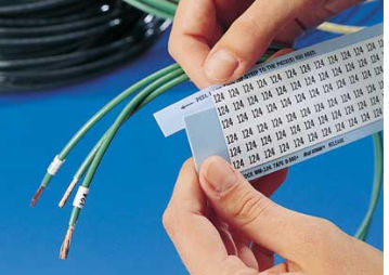
You've probably seen that you can purchase a little notebook of wire identification letters and numbers that are quite convenient, small and clearly printed and durable.
An example of a product that I've used for many years is the
- Brady Black on White Wire Marker, Vinyl Cloth B500, No. of Labels: 900 [PK/25] Model: WM-9-PK - illustrated above.
Brady, 6555 W. Good Hope Rd Milwaukee, WI 53223 Phone: 888-250-3082 Website https://www.bradyid.com/
These wire labels are sold at electrical suppliers, online vendors, etc. Brady sells so many types of labels and labeling equipment as well as other electrical products, signs, tags, etc. that one can but comment: they don't sell just one thing.
On 2019-11-22 by Casey Jones
I have two GFI protected circuits distributed in the same conduit runs. The neutrals need to be kept independent for the GFI sampling to operate correctly.
Is there an accepted method of identifying these independent neutrals? Thank you.
can't get an electrical switch to work on a combined receptacle-switch device
(July 30, 2014) Anne
I am replacing an outlet that has the top half on a switch and the bottom half always on.
The old outlet had stab wire connections for a black, white and RED wire in the top section.
I have tried to install the new outlet, using the screws as recommended, rather than the stab connections, and cannot make the top half work on the switch.
(I tried with the tabs in place, one tab removed and both tabs removed. Also tried the red & black on the same screw, red on the screw and black in the stab hole and the reverse.) How to I make the switch work?
Reply:
Anne I don't have a full picture of what you're doing but
first: be careful not to electrocute yourself or start a fire - a standard caveat I'd make to anyone not a trained electrician
Now, in general,
1. to power the upper and lower halves of a receptacle separately we have to break the line-in or black wire or power tab. You can break apart the tab on the white wire neutral side but those connections are going to be made common by a splice in the electrical box anyway.
2. The line-in power wire into the receptacle box is split into two feed wires.
One goes to the lower "always on" half of the receptacle line in screw while the other connects to a wire leading to the receptacle switch.
The return wire from that switch then connects to the line-in or black wire or gold-colored screw on the receptacle.
Question:
(Oct 30, 2014) James
I am an apprentice in house wiring I wired a four plate stove like this: I installed 30A circuit breaker in the consumer unit and ran wires to the kitchen where I connected the wires coming from the breaker box to the line (input) an I connected the load to the stove I used 2.5mm
I tested the it and is working but now my question is did I do it right? is the 2.5mm OK for the circuit? Is there a negative impact the wire size will have in future?
Reply:
James you don't identify your country nor voltage levels. Typically an electric stove is wired on a 220V-240V circuit, sometimes depending on stove design, some burners may use always or part time just one 120V leg. I'm not quite clear on what you did. Did the 4-plate electric stove come with wiring instructions and a wiring diagram?
Tom Planer doesn't like photos of electrical wiring details
Tom Planer
I would be embarrassed to say I allowed the pictures in this article to be a part of this page.
You really need to take a quick look at NFPA Article 110.3 and 110.4 and do it quick.
Tom
Reply:
Tom, thank you for your comment.
Indeed I expect licensed electricians to know how to make proper electrical connections.
And to be familiar with the national electrical code. We do, however, often include photographs of as-is wiring as important illustrations of what's found in the real world - in the field. Showing what people actually do, right and wrong, can be useful.
While we regret that you might be embarrassed, explicit, technical comment would be more helpful than shame tossed over the electronic-wall.
Your comment to look at NFPA Article 110.3 probably intended to refer to the National Electrical Code NEC 110.3 which gives advice for the examination, installation, and use of [electrical] equipment and includes the expectation that such wiring details are inspected by the local electrical code compliance officer.
NEC 110.4 includes "The voltage rating of electrical equipment shall not be less than the nominal voltage of a circuit to which it is connected. "
Referring readers to a mere paragraph number that points to lengthy electrical code specification without any specifics is not helpful.
Thanks - Moderator.
...
Continue reading at ELECTRICAL RECEPTACLE CONNECTION DETAILS or select a topic from the closely-related articles below, or see the complete ARTICLE INDEX.
Or see these
Recommended Articles
- ELECTRICAL OUTLET, HOW TO ADD & WIRE - home
- ELECTRICAL OUTLET ADAPTER SHORT CIRCUIT
- ELECTRICAL RECEPTACLE ARC PITTING
- ELECTRICAL RECEPTACLE CONNECTION DETAILS
- 2-WIRE RECEPTACLE CONNECTIONS
- WHICH SCREWS GET the BLACK, WHITE & GROUND WIRES ?
- WHICH WIRES GO to LINE or LOAD CONNECTIONS?
- HOW to CONNECT WIRES to a RECEPTACLE or SWITCH
- GROUND WIRE CONNECTION SUMMARY
- NUMBER of WIRES NEEDED: 2-WIRE, 3-WIRE, 2 or 3 WITH GROUND?
- ELECTRICAL DUPLEX RECEPTACLE WIRING
- ELECTRICAL OUTLET, HOW TO ADD in OLDER HOME
- ELECTRICAL RECEPTACLE WIRING SERIES vs PARALLEL
- ELECTRICAL SPLIT RECEPTACLE WIRING
- WIRES TOO SHORT TO CONNECT, REPAIR FOR
- GROUND WIRE CONNECTIONS
Suggested citation for this web page
ELECTRICAL RECEPTACLE WIRING SERIES vs PARALLEL at InspectApedia.com - online encyclopedia of building & environmental inspection, testing, diagnosis, repair, & problem prevention advice.
Or see this
INDEX to RELATED ARTICLES: ARTICLE INDEX to ELECTRICAL INSPECTION & TESTING
Or use the SEARCH BOX found below to Ask a Question or Search InspectApedia
Ask a Question or Search InspectApedia
Share this article:Try the search box just below, or if you prefer, post a question or comment in the Comments box below and we will respond promptly.
Search the InspectApedia website
Note: appearance of your Comment below may be delayed: if your comment contains an image, photograph, web link, or text that looks to the software as if it might be a web link, your posting will appear after it has been approved by a moderator. Apologies for the delay.
Only one image can be added per comment but you can post as many comments, and therefore images, as you like.
You will not receive a notification when a response to your question has been posted.
Please bookmark this page to make it easy for you to check back for our response.
IF above you see "Comment Form is loading comments..." then COMMENT BOX - countable.ca / bawkbox.com IS NOT WORKING.
In any case you are welcome to send an email directly to us at InspectApedia.com at editor@inspectApedia.com
We'll reply to you directly. Please help us help you by noting, in your email, the URL of the InspectApedia page where you wanted to comment.
Citations & References
In addition to any citations in the article above, a full list is available on request.
- Timothy Hemm has provided photographs of various electrical defects used at the InspectAPedia TM Website. Mr. Hemm is a professional electrical inspector in Yucala, CA.
- Mark Cramer Inspection Services Mark Cramer, Tampa Florida, Mr. Cramer is a past president of ASHI, the American Society of Home Inspectors and is a Florida home inspector and home inspection educator. Mr. Cramer serves on the ASHI Home Inspection Standards. Contact Mark Cramer at: 727-595-4211 mark@BestTampaInspector.com
- John Cranor [Website: /www.house-whisperer.com ] is an ASHI member and a home inspector (The House Whisperer) is located in Glen Allen, VA 23060. He is also a contributor to InspectApedia.com in several technical areas such as plumbing and appliances (dryer vents). Contact Mr. Cranor at 804-873-8534 or by Email: johncranor@verizon.net
- Resnick, Robert; Halliday, David (1966). "Chapter 32". Physics. Vol. I and II (Combined international ed.). Wiley. LCCN 66-11527. Example 1.
- Encyclopedia Britannica, "Parallel circuits" - retrieved 2022/08/08, original source: https://www.britannica.com/technology/parallel-circuit
- Encyclopedia Britannica, "Series circuit" - retrieved 2022/08/08, original source: https://www.britannica.com/technology/series-circuit
- Wikipedia, "Series and parallel circuits" - retrieved 2022/08/08, original source: en.wikipedia.org/wiki/Series_and_parallel_circuits#cite_note-Resnick_1966-1
- [5] Special thanks to our reader Steve who pointed out prior errors in our illustrations.
- [6] Simpson Strong-Tie, "Code Compliant Repair and Protection Guide for the Installation of Utilities in Wood Frame Construction", web search 5/21/12, original source strongtie.com/ftp/fliers/F-REPRPROTECT09.pdf, [copy on file as /Structures/Framing/Simpson_Framing_Protectors.pdf ]. "The information in this guide is a summary of requirements from the 2003, 2006 and 2009 International Residential Code (IRC), International Building Code (IBC), International Plumbing Code (IPC), International Mechanical Code (IMC), 2006 Uniform Plumbing Code (UPC) and the 2005 National Electrical Code."
- "Electrical System Inspection Basics," Richard C. Wolcott, ASHI 8th Annual Education Conference, Boston 1985.
- "Simplified Electrical Wiring," Sears, Roebuck and Co., 15705 (F5428) Rev. 4-77 1977 [Lots of sketches of older-type service panels.]
- "How to plan and install electric wiring for homes, farms, garages, shops," Montgomery Ward Co., 83-850.
- "Simplified Electrical Wiring," Sears, Roebuck and Co., 15705 (F5428) Rev. 4-77 1977 [Lots of sketches of older-type service panels.]
- "Home Wiring Inspection," Roswell W. Ard, Rodale's New Shelter, July/August, 1985 p. 35-40.
- "Evaluating Wiring in Older Minnesota Homes," Agricultural Extension Service, University of Minnesota, St. Paul, Minnesota 55108.
- "Electrical Systems," A Training Manual for Home Inspectors, Alfred L. Alk, American Society of Home Inspectors (ASHI), 1987, available from ASHI. [DF NOTE: I do NOT recommend this obsolete publication, though it was cited in the original Journal article as it contains unsafe inaccuracies]
- "Basic Housing Inspection," US DHEW, S352.75 U48, p.144, out of print, but is available in most state libraries.
- In addition to citations & references found in this article, see the research citations given at the end of the related articles found at our suggested
CONTINUE READING or RECOMMENDED ARTICLES.
- Carson, Dunlop & Associates Ltd., 120 Carlton Street Suite 407, Toronto ON M5A 4K2. Tel: (416) 964-9415 1-800-268-7070 Email: info@carsondunlop.com. Alan Carson is a past president of ASHI, the American Society of Home Inspectors.
Thanks to Alan Carson and Bob Dunlop, for permission for InspectAPedia to use text excerpts from The HOME REFERENCE BOOK - the Encyclopedia of Homes and to use illustrations from The ILLUSTRATED HOME .
Carson Dunlop Associates provides extensive home inspection education and report writing material. In gratitude we provide links to tsome Carson Dunlop Associates products and services.
 |
HOME | ABOUT | ASK a QUESTION | CONTACT | CONTENT USE POLICY | DESCRIPTION | POLICIES | PRIVACY | |
| © 2026 - 1985 Publisher InspectApedia.com - Daniel Friedman | |||||||||