
InspectAPedia®FREE Encyclopedia of Building & Environmental Construction, Diagnosis, Maintenance & Repair |
Question? Just ask us! InspectAPedia
|
 Air Flow Rate (CFM) Measurement
Methods, Tools, & air flow measurement data for buildings, air conditioners, warm air furnaces

- POST a QUESTION or COMMENT about air flow rate or CFM measurement methods & typical rates in buildings and in HVAC systems
Air flow rate measurement instruments for fpm or CFM:
this article defines air flow rate or cubic feet per minute (CFM) as the term is used to describe building air conditioners, heating systems, or building air movement rates.
We describe the types of devices or instruments used to measure air flow, comparing the features, operation, and accuracy of each approach.
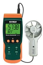
We include a list of air flow rate measurement instrument or tool suppliers - where to buy CFM measurement equipment. Page top photo illustrates an example of a vane anemometer produced by Extech, the Extech ExTech SDL300 Anemometer and data logger - www.extech.com [permission requested 9/12/12]
InspectAPedia tolerates no conflicts of interest. We have no relationship with advertisers, products, or services discussed at this website.
- Daniel Friedman, Publisher/Editor/Author - See WHO ARE WE?
Definitions, Procedures & Tools for Measuring Air Flow Rates (CFM)
Discussed here: how to measure air movement or flow rates in buildings; how to measure HVAC duct supply or return air flow rates in CFM or by other standards.
What tools to use to measure air flow rate, accuracy, procedures, & where to buy.
Definitions, Procedures & Tools for Measurements of Air Flow Rates (CFM) in Buildings.
If you want to know typical air flow rates in ductwork, air handlers, and HVAC equipment see this
separate article - AIR FLOW RATES in HVAC SYSTEMS
Article Contents
- AIR FLOW MEASUREMENT CFM
- AIR FLOW RATE MEASUREMENT DEFINITION
- AIR FLOW RATE MEASUREMENT ACCURACY
- AIR VELOCITY MEASUREMENT & STANDARDS
- AIR FLOW RATE CFM MEASUREMENT DEVICES & METHODS
- ANEMOMETERS: Cup Type anemometers used to measure wind speed
- ANEMOMETERS: Vane / Fan Blade Anemometers used for air flow rate measurements
- ANEMOMETERS: Swing Vane Anemometers used for air flow measurements
- HVAC DUCT AIR FLOW MONITORS
- PITOT TUBES probes for air flow measurements
- PRESSURE TRANSDUCERS for air flow measurements
- "HOT WIRE" CFM measurements using a hot wire anemometer
- CAPTURE HOODS for air flow measurements
- LIQUID COLUMN GAUGES - liquid column manometers used for air pressure or air flow measurements
- TOILET PAPER or Tissue Test Confirmation of Air Flow
- AIR FLOW & CFM DEVICE SUPPLIERS Air Flow CFM Measurement Devices for HVAC Systems
- AIR FLOW RATES in HVAC SYSTEMS
Measurement Air Conditioner or Heating System Air Flow CFM
 Question:
how do I measure the CFM of my air conditioner or heating system ?
Question:
how do I measure the CFM of my air conditioner or heating system ?

How is CFM measured? - Anon.
Reply: Definition of Air Flow Rate & Flow Rate Measurement: Air flow quantity & air velocity
Definition of Air Flow Rate
The Air flow rate for an HVAC system is defined as the volume of air being delivered at some speed or "rate", typically cubic feet per minute (CFM) or m/sec (meters per second), ft/sec (feet per second), or ft/min (feet per minute).
Air flow rate, or quantity of air being moved, is measured in m3/sec (cubic meters per second) or cubic feet per minute (CFM).
See TYPICAL AIR FLOW RATE CFM Specifications for HVAC equipment - for typical air flow rates in cooling and in heating mode.
We can also measure air velocity or air speed without necessarily knowing the total quantity of air being moved.
Air velocity or air speed is measured in m/s (meters per second) or feet/minute. Details are
at AIR VELOCITY MEASUREMENT & STANDARDS
Some instruments can measure both air velocity (air speed) and air flow rate (air quantity).
Definition of Air Flow Measurement
Air flow rate is measured by calculating an average velocity for the conduit of interest, and then, multiplying this velocity by the cross sectional area of the duct at the measurement location.
The air velocity value may estimated using a single reading, or a survey across the duct at a station. - Flow Kinetics: - [12]
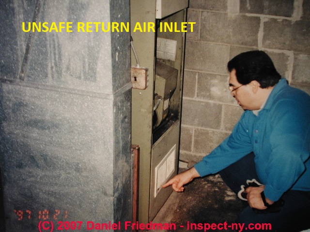
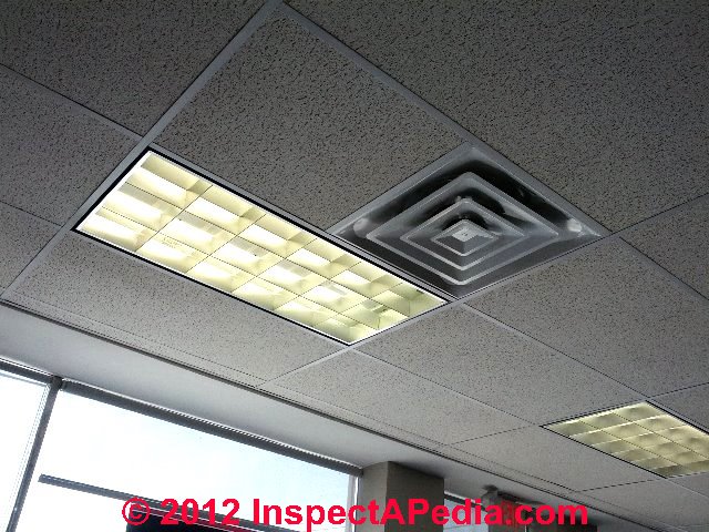
Our HVAC air duct register photos above and below illustrate two common air flow measurement points in a duct system: at the return air inlet (unsafe in the above photo left) and at a supply air register (below left).
We make the actual measurement of air flow in a cooling or heating system by using an instrument that is sensitive to the passage of air. This article describes the different types of air flow measurement instruments and how each works.
The accuracy of air flow rates measured in cooling or heating system air handler or duct systems is discussed at ACCURACY of CFM or other air flow measurements on HVAC systems.
Simple Air Flow Calculation
If I held up a one-foot square sensor in front of an air source (say an air supply register) and the sensor measured air velocity at 12 inches per minute, I'd be measuring 1 CFM of airflow. (One cubic foot = 12 x 12 x 12 inches).
Or if we measured an air velocity at an air supply register of one foot per minute and we knew that the duct work was a 12-inch square duct, we'd figure we were seeing one cubic foot per minute of air supply at that location.
Actually here are more than one answer to your question about how airflow is measured in an HVAC system because there is a range of air flow measurement instruments on the market.
The measuring devices vary in price, accuracy, and in operating principle, and there are also of course multiple sources of CFM data: manufacturers specifications, theoretical numbers, and actual measurements. We are most interested in the last category.
Accuracy of CFM or other air flow measurements on HVAC systems such as air conditioners or heaters
CFM measurements on HVAC systems should be considered an approximation not precision measurements. There are a number of sources of uncertainty even in the measurement itself.
For most HVAC air flow troubleshooting or air balancing applications, we are more interested in comparison measurements of air flow between different locations in the HVAC duct system than in high precision in statement of air flow itself.
OPINION: Therefore while pitot-tube type instruments and some electronic air flow measurement instruments can offer both precision and accuracy in HVAC or building air flow measurements, all of the instruments described in our article above can work suitably for heating and air conditioning design and maintenance.
Air Velocity Standards & Measurements
 Earlier at AIR FLOW RATE MEASUREMENT DEFINITION we explain that the total quantity of air entering (or leaving) an enclosed space is measured in cubic feet per minute or CFM, or in some countries cubic meters per minute or M3/Min.
Here we discuss air velocity or air speed measurements and standards.
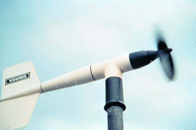
Simple wind speed in an open space is measured by a wind speed anemometer.
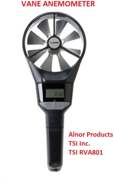
We make similar measurements of air speed at air conditioning or heating system supply or return registers or at air handlers but we use smaller, simpler instruments like the vane anemometeer shown here.
For purposes such as rating air filters or air cleaning equipment we measure the simple speed with which air is moving, such as the speed of air movement across a cooling coil (evaporator coil) or the speed of air movement through an air filter.
Illustration: a vane anemometer, model RVA801, produced by Alnor Products, TSI Incorporated.
See AIR FLOW & CFM DEVICE SUPPLIERS.
Definition of air speed or air velocity
Air velocity is the rate of movement of air in a particular direction, expressed as feet per second or meters per second.
We are simply measuing the air flow rate or speed at a specific point or location.
How do we measure air velocity?
The most common air flow measurement device used in HVAC systems is a hand-held vane anemometer or a hand-held hot-wire anemometer.
The vane anemometer is in essence a small fan driven by the movement of air across the fan blades.
The hot wire anemometer uses a heated wire that is cooled by the movement of air across the wire.
Some devices such as the Amprobe TMA 10A Anemometer with remote vane/sensor can measure air velocity (air speed in ft/min or meters/sec) and air flow rate (m3/sec or ft/min), and air temperature.
At AIR FLOW RATE CFM MEASUREMENT DEVICES & METHODS we describe various air flow measurement devices.
Air Flow Rate CFM & Air Velocity FPM Measurement Devices & Approaches
Cup-Type Wind Speed Anemometers & Data Loggers
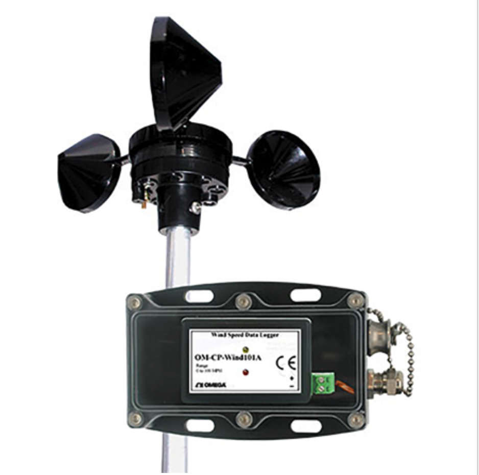 Shown here: Spectris Omega Wind Speed Data Logger No. OM-CP-WIND101A-KIT.
The cup type anemometer is familar if you've looked around a local weather station or airport. The movement of air across the rotating cups causes the shaft to turn at a rate that is measured by a wind speed indicator or in the case of this instrument from Spectris, a wind speed data recorder.
Here are excerpts from the manufacturer's product description:
The OM-CP-WIND101A is a complete system to accurately measure and record wind speed.
This low cost wind speed recording system comes complete with a data logger, weatherproof enclosure, a three-cup anemometer and all the necessary cabling to quickly get up-and-running.
Measurement Range: 0 to 100 mph (0 to 45 m/s)
Resolution: 0.085 mph at 10 second reading interval
Accuracy: ±2.0 mph from 0 to 10 mph; ±2.5% of reading from >10 to 100 mph
Starting Threshold: 1.75 mph &
Reading Rate: 1 reading every second to 1 every 24 hours. - Omega, cited in detail
at AIR FLOW & CFM DEVICE SUPPLIERS.
Duct Airflow Monitors

Above: the Dwyer Instruments FLST airflow rate monitoring device intended for monitoring air flow rates in an HVAC duct system.
The Dwyer Instruments FLST (illustrated here) is indeed an air duct flow rate sensing system (used in connection with additional instrumentation) described by the manufacturer as:
The SERIES FLST Airflow Measurement Station utilizes an airflow averaging element generating a velocity pressure signal similar to the orifice, venturi, and other primary elements. Single or multiple airflow elements are factory mounted and pre-piped in a casing designed for flanged connection to the ductwork.
Multiple elements are joined together for connection to a differential measurement device (gage, transmitter, etc.) for flow measurement and indication purposes.
... Standard airflow stations can be operated (in air) continuously in temperatures up to 350°F or intermittently in temperatures up to 400°F. ... monitoring airflow rates from 100 to 10,000 fpm (0.51 to 51 m/s)
The airflow averaging element, utilized in the FLST, is a head type device, which generates a differential (velocity) pressure signal similar to the orifice, venturi, and other head producing primary elements.
The FLST is constructed so that strategically located sensing ports (based on duct size) continually sample the total and static pressures, when inserted normal to flow.
The total pressures sensed by the upstream ports are continually averaged within the element in an isolated chamber. The static sensing ports (located where the influence of the velocity head is zero) are averaged in a second isolation chamber
. Multiple elements are manifolded together for connection to a differential measurement device (gage, transmitter, etc.) for flow measurement and indication purposes.
In essence a grid of sensing tubes is mounted in a rectangular, round, or oval frame to mount in the HVAC duct system.
Watch out: However, depending on the particle size and dust levels in the air system you describe "carrying wood dust and flakes", there is likely to be a problem with fouling or clogging of the sensing holes in the FLST tube openings. The company's description of maintenance recommendations gives some insight into this problem, though you'll want to discuss your specific application with them further.
MAINTENANCE
Since the sensing elements have no moving parts, only periodic cleaning may be required. The sensing elements should be inspected for fouling of the sensing holes as part of an annual preventative maintenance program.
Installations having viscous airborne particles may require more frequent inspection. If the sensing holes on the elements have become fouled or plugged, the following procedure is recommended. Caution, all instruments must be isolated (removed) from the sensing lines prior to performing the following cleaning procedure.
and
Cleaning: In applications where the sensing elements are subject to viscous contaminants it is recommended that the surface be washed with a cleaning agent. The cleaning agent used must be suitable for use on the type of material the sensing element is constructed
of (i.e. aluminum, stainless steel, etc.)
The Series FLST Duct Mounted Airflow Measurement Station is not field serviceable and should be returned if repair is needed (field repair should not be attempted and may void warranty).
Be sure to include a brief description of the problem plus any relevant application notes. Contact customer service to receive a return goods authorization number before shipping. - retrieved 2017/05/11, original source http://www.dwyer-inst.com/PDF_files/FLST_iom.pdf
How Vane / Fan Blade Anemometers are used for air flow rate measurements
 Vane or Fan Blade Anemometers, for Fan type air flow measurement: these are the most commonly used lower-cost CFM measurement devices used by home inspectors and HVAC technicians.
Above left is a wind speed anemometer - Wikipedia creative commons.
At page top we illustrate the Extech ExTech SDL300 Anemometer and data logger available from www.extech.com. [19]
Some anemometers are comparatively small inexpensive (and less precise) air flow measurement devices that use a hand-held fan like instrument such as the Kanomax vane anemometers 6800 series or the ExTech SDL300 shown at page top) to measure air flow in CFM or equivalent rates on other scales.
A hand-held portable fan blade anemometer device is held in the air path and moving air rotates a fan blade. The instrument measures fan blade rotation to calculate a flow rate or pressure equivalent that is combined with the known cross sectional area of the measurement device.
An advantage of measuring CFM with an anemometer is that you don't need to correct the measurement for temperature (variation in air density). Another advantage is that some of these instruments are very low in costs.
Choose a unit that measures in the range of air speed in CFM specified by the standards against which you are measuring for your application.
Tip: always choose an instrument whose scale focuses most-closely on the measurement value range in which you're interested. That will generally give more-accurate readings.
For example, choosing an anemometer that can measure between 0.3 m/second = 5.15 cubic feet per minute - and 30 m/s = about 515 cfm - covers the necessary air speeds (20 to 100 cfm) for tests of bathroom and kitchen ventilation fans in North America.
If you were interested in the bath and kitchen vent fan standard and measurements for its compliance, using New York City's standard as an example the air flow speeds of interest are
- Kitchen ventilation fan requirements: 100 cfm (intermittent) or 25 cfm (continuous) (cfm = cubic feet per minute)
- Bathroom ventilation fan requirements: 50 cfm (intermittent) or 20 cfm (continuous)
Choosing an instrument that is designed to measure wind (air) speeds of 100 mph is likely to get one that is inaccurate over its scale for very low air speeds such as at a building vent fan.
Choosing an instrument that is designed to measure air speeds extending only up to 5 meters/second would, on the other hand, be unable to register higher wind speeds of interest to meteorologists and sailors.
Watch out: a more-accurate measurement of air flow in a duct system probably requires the user to insert an instrument actually inside the duct - such as a hot wire anemometer.
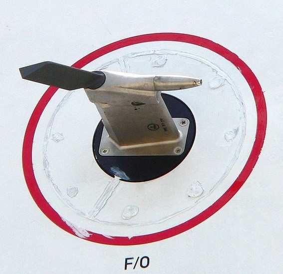
Swing Vane Anemometers used for air flow measurements
Swing Vane Anemometers: using a vane or ball that moves along a curved scale are used to measure low velocity air (25 to 400 feet per minute) for checking wind speed or for measuring the air flow rate in duct work, at air filters (is the air filter dirty and needing replacement?), and to meet safety ventilation requirements for OSHA and the US EPA for safety exhaust hoods, spray booths and similar applications.
Pitot tube probes used for air flow measurements
Pitot tube probes: a Pitot tube (invented by Henri Pitot (1732)) is a device that measures air (or other flowing gas or liquid) pressure when the tube is inserted or placed in the proper position (pointed into the direction from which air flow emanates) for sensing airflow.
The pressure is converted to a flow rate by considering the cross-sectional area of the duct or opening through which air is being delivered. (There are some assumptions behind this including that air flow rate is uniform across the cross section of the opening.)
By comparing the dynamic (moving air) pressure to static (non-moving air) pressure a pitot tube can give very accurate air flow velocity data.
Pitot tube image, Wikipedia creative commons. [25]
Quoting Flow Kinetics who offer instruments for air flow measurement as well as excellent technical publications on this topic illustrate a device used fro CFM measurement by measuring air pressure.[12][13]
The (incompressible) velocity measured by a Pitot tube is calculated from the recorded differential pressure, Dp, and density, r, of the fluid. [12][13]
Of course in our case the "fluid" is air and we're interested in air movement through ductwork or out of a supply register into a building space.
Pitot tubes are familiar to air travelers who have noticed that little tube sticking down and pointing forward from the bottom of many aircraft where the pitot tube is used to measure the air speed of the craft. Indeed pitot tubes are used for high velocity airflow measurements where a vane anemometer could not possibly be up to the task.
Pitot tubes are the most accurate technology for measuring air flow rates and are generally used to provide the accuracy standard for comparison with other CFM measurement devices.
How Pressure Transducers are used for air flow measurements
Pressure transducers: also measure pressure from a flowing gas or air and permit conversion to CFM measurements in the same manner as a pitot tube - knowing the cross sectional area of the duct or opening.
Pressure sensors measure the force exerted by a "fluid" including air or liquid by measuring the force that would be necessary to stop that movement. These devices are also called pressure transmitters, pressure senders, pressure indicators, piezometers, and in HVAC equipment and testing, manometers.[14]
Actual measurements of airflow in an HVAC system or at air supply registers are expressed in cubic feet per minute and are most often made in the field using a hand held flow meter through which air moves. The flow meter is calibrated based on the its input area and the resistance offered by its own fan blades.
As air, say coming out of an air supply duct, blows through the handheld device it causes the device fan or sensor to move, giving a measurement of calculated air flow in cubic feet per minute at that location and time.
Watch Out: however: measuring CFM at a supply register is not at all the whole story since air flow varies throughout the system as it is affected by internal resistances such as bends, crimps, surface smoothness, duct length, etc.
And air flow through rectangular duct work is not identical to air flow CFM through a round duct of the same cross-sectional area.
"Hot wire" CFM measurements using a hot wire anemometer
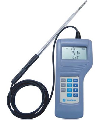
An anemometer type device that uses a heated wire and measures the cooling effect of low velocity air flow can also be used to estimate air flow rates provided that air temperature is also considered to provide a correct estimate of air flow rate.
The GrayWolf Advanced Sense HVAC differential pressure manometer works on this principle using a hot wire probe inserted into the HVAC duct.
Also see the Kanomax A031 hot wire anemometer (photo at left, kanomax-usa.com, described below. ) [24]
Note: all of the air measurement instrument manufacturers listed in this article produce a range of air flow rate monitoring instruments (and other test equipment) providing a variety of functions, accuracy, and of course, price.
Capture Hoods for air flow measurements
Capture Hoods can be used to make accurate measurements of air flow rates at HVAC system air supply registers. Capture hoods cover the entire supply air register and use a differential pressure device or a hot wire device to obtain an air flow CFM number.
How Liquid Column gauges - liquid column manometers are used for air pressure or air flow measurements
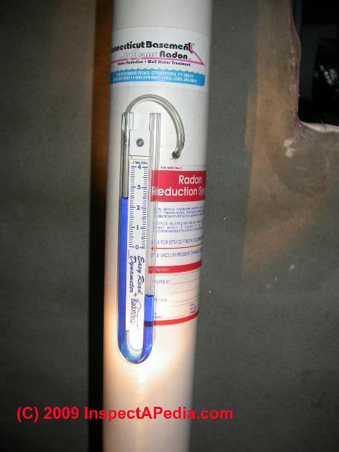
Liquid Column gauges - liquid column manometers are a special form of liquid-column manometer used to measure low velocity air flow by comparing air pressure inside and outside of two spaces.
Above the U-shaped plastic tube filled with a blue liquid is connected at its left end to the interior of a 6" plastic vertical exhaust duct forming part of a radon mitigation system.
The right end of the liquid column gauge is simply open to the atmosphere of the room, in this case a basement.
The differential in air pressure between the two ends of the tube is marked on a scale indicating the air flow rate inside of the column.
The difference in height between the two ends of the column of blue liquid is always in direct proportion to the difference between the two air pressures (inside & outside of the exhaust duct). If no air were flowing inside of the white exhaust duct, the two ends of the blue liquid would be at the same level.
In this application, air flowing past the end of the flexible plastic tube inserted into the column interior causes a reduction of air pressure in the tube that is a function of the speed of air flow past the tube opening.
In this application the liquid column gauge reading of differential air pressure does not have to be precise as its function is simply to indicate that there is some difference in air pressure between the room interior and the exhaust duct interior.
As long as the room is at higher pressure than the column interior, the exhaust system is working and any radon gas below the floor slab (in this application) tends to exhaust through the duct rather than enter the room.
Toilet Paper or Tissue Confirmation of Air Flow
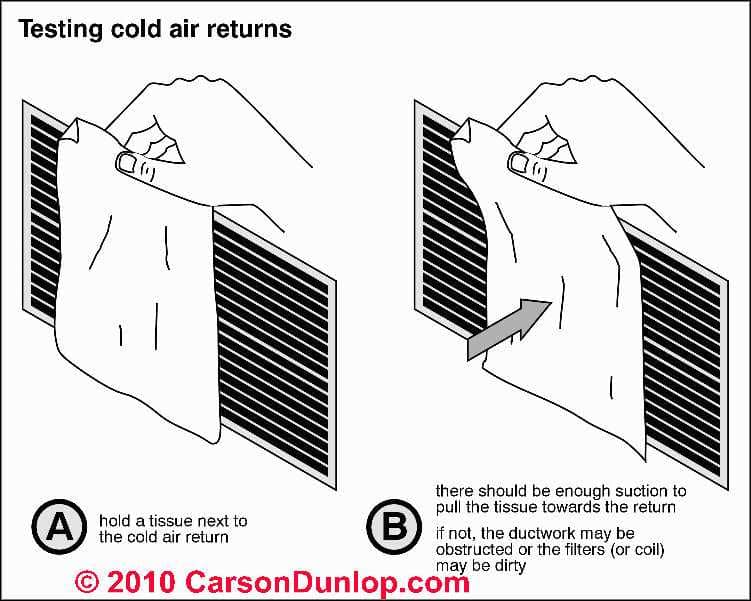
A simple test for air movement at the return air inlet is illustrated in our sketch.
Just hold a tissue or piece of toilet paper near the inlet grille face.
If air is moving into the grille the tissue will be pulled against the opening.
This toilet paper or tissue test can confirm air flow as well as the direction of air movement at an HVAC air supply or return air register, and is a useful, if trivial, demonstration that can help confirm air movement when air flow in the system is weak or uncertain.
Watch out: Obviously, this is a subjective, non-quantitative test for air movement at a building location. This test can tell you the direction of air flow but it is not accurate for much more than that.
Sketch above courtesy of Carson Dunlop Associates, a Toronto home inspection, education & report writing tool company [ carsondunlop.com ].
at AIR MOVEMENT in BUILDINGS we illustrate another toilet tissue test by taping a tissue to the bottom of an open window sash in a New York building.
Where to Buy Air Flow CFM Measurement Devices for HVAC Systems
- Alnor Products, TSI Incorporated, Website: www.alnor.com, Tel: USA: 1-800-874-2811, India: +91 80 678 77200, Singapore: +65 6595 6388
Shown here: Alnor Rotating Vane Anemometer Model RVA501 / RVA 801 Product Specifications [PDF] - Amprobe Corporation,
6920 Seaway Blvd
PO Box 9090
Everett, WA 98203 USA Email:
info@amprobe.com
Tel: 1-877-AMPROBE (267-7623) website: http://www.amprobe.com/
Example product:
Amprobe TMA 10A Anemometer with remote vane/sensor can measure air velocity, air flow rate, and air temperature. - Dwyer Instruments, 102 Indiana Hwy. 212
(P.O. Box 373)
Michigan City, IN 46360 (46361) USA, Website: www.dwyer-inst.com/flowmeters distributes Kanomax Anemometer Air Flow Meters such as the Anemometer LITE Model 6006 or for HVAC testing their vane anemometer, the Dwyer Instruments Anemometer Model A031.
See also our description of the Dwyer Instruments FLST airflow monitoring device.
Contact points for Dwyer Instruments who operate world-wide:
- In the UK contact Dwyer Instruments at Unit 16, The Wye Estate, London Road, High Wycombe, Bucks HP11 1LH-U.K. Phone: +44 (0) 1494 461707
- In the U.S. contact Dwyer Instruments at 102 Indiana Hwy. 212, (P.O. Box 373) Michigan City, IN 46360 (46361) USA Phone: 219/879-8000
- In Australia contact Dwyer at Unit 1, 11 Waverly Drive P.O. Box 359 Unanderra, NSW 2526 Australia Phone: 61 2 4272 2055
- The company also has offices in Singapore, Hong Kong, South America, South Africa, the Middle East and India
- Extech Instruments Corporation
9 Townsend West
Nashua, NH 03063
U.S.A., Tel: 877-239-8324, Website: http://www.extech.com, Email: sales@extech.com ExTech_SDL300data.pdf
Example product:
ExTech 0.4 -30 m/Sec Air CFM & CMM Thermo-Anemometer EXTECH Model AN100 USERS MANUAL [PDF] retrieved 2018/06/21, original source: http://www.extech.com/resources/AN100_UM-en.pdf - FlowKinetics LLC, 528 Helena Street Bryan, Texas 77801 USA, Tel: (979) 680-0659, Email: inform@flowkinetics.com, Website: www.flowkinetics.com
- GrayWolf Sensing Solutions, 6 Research Dr., Shelton CT 06484, USA, Tel: 800-218-7997, email: salesteam@wolfsensing.com differential pressure manometers, Website: www.wolfsense.com (hot wire air velocity probes). The company has offices in Clare, Ireland as well.
- Holdpeak Instruments, Zhuhai JiDa Huapo Instrument Company, produces anemometers including the HoldPeak 866B Digital Anemometer - Wind Speed Meter.
Watch out: this website may be hacked or may contain worms or viruses, ref. google Search 2017/08/02. - Kanomax Anemometers, Website:kanomax-usa.com, e.g. Kanomax Anemomaster Model A041, (straight-probe type hot wire anemometer typically for HVAC system use), retrieved 9/12/12, original source: http://www.kanomax-usa.com/product_catalog/Kanomax_A031.pdf [copy on file as Kanomax_A031.pdf]
- Omega.com, Tel: 800-TC-OMEGA, US and Canada:
1-888-826-6342
International:
1-203-359-1660website: http://www.omega.com, offices world wide.
The Omega Wind Speed Data Logger OM-CP-WIND101A kit (about $450. U.S.D.) is shown above at ANEMOMETERS: Cup Type - Proster Instruments, Email: prosteramz@gmail.com, Website: http://www.prostereu.com/, Wind Speed MEasuring Instruments, Proster PST TL090 LCD Digital Wind Speed Scale Gauge Meter and Proster TLl1097 Handheld Anemometer Wind Speed Meter Scale Gauge. Note that the manufacturer's description does not include HVAC system or building air movement measurements.
Proster Handheld LCD Digital Anemometer Wind Speed Meter with Backlight : Use to Measure Wind Speed and Temperature; Ideal for Windsurfing; Flying Kite, Aeromodelling and UAV; Sailing; Surfing; Fishing; Hiking and Other Outdoor Activities - CONTACT us to add a listing here. No fees, no conflicts of interest.
Question: instruments for measuring of air flow rate in-line exhaust fans exist (at the end of a duct)
Could you please tell me is there any instrument for measuring of air flower rate in-line exhaust fans exist(at the end of a duct). We have not possibility and space for inside measuring at duct. We are thinking to find some way to measure from outside of duct. The diameter of duct( pipe) is 40-50 cm. Air temperature is 5-40 centigrade. Humidity =60-100 %
The duct is circular pipe with 40 Cm diameter.
Do you think the suggested instruments could measuring accurately on turbulence air flow?
Where we should put anemometer, before fan or after fan in Duct?
Please feel free to write me back for further questions.
I look forward to hearing from you. - D.K. by private email, 2016/03/21, The Netherlands
Reply:
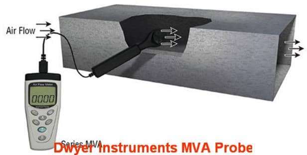
Above: the Dwyer MVA duct or vent airflow measurement probe system. Below the Dwyer DAFM airflow measuring probe.
Yes there are permanent, temporary, and hand-held probes that can measure air-flow inside of an air duct system.
I should have added you ought to be able to make an opening to insert a probe to measure airflow. That makes some older-style hand-held anemometers a bit large and inconvenient as you'd have to cut and perhaps seal around a larger opening, but other devices avoid that trouble as I'll cite below.
Dwyer instruments (and other HVAC duct airflow instrument manufacturers) make in-duct airflow measurement systems. You can install a permanently-mounted air flow measuring device in line in the duct system. Dwyer also has insertable probe devices.

There are at least 3 options. Here are an excerpta from Dwyer Instruments.
- The Dwyer Instruments FLST series are permanently-mounted airflow sensors. These are mounted inline in a duct or vent system to permit continuous airflow rate monitoring & control.
- Dwyer Portable insertable hand-held anemometers from Dwyer include their MVA series.
Excerpt:
Handheld anemometers are an excellent, portable tool for performing tests on HVAC system performance; however, large rotating vanes can prevent easy access to ducts. Dwyer introduces the Model VT-200 Vane Thermo-Anemometer to eliminate this problem. Additionally, simple keypad programming enables the user to view volumetric flow rates in CFM or CMM.
Data logging software is also available to easily record and view data on a PC or laptop. - Retrieved 2016/03/21, original s: http://www.dwyer-inst.com/ApplicationGuides/?ID=30 - Dwyer Portable insertable and probably more accureate (after the duct has been completed) series is DAFM The number of probes needed depends on duct shape and size but *round* duct need only 2 probes regardless of duct dimension.
Excerpt:
DAFM The Model DAFM Duct Air Flow Measuring Probe uses evenly distributed total and static pressure measuring points to deliver an accurate measurement of flows in a duct. The Air Flow Measuring Probe can be completely installed from outside of the duct making it very easy to install.
With its lightweight and durable construction in addition to its ease of installation, this product lends itself to being used in the HVAC industry. These air flow measuring probes may be ordered for either round or rectangular ducts. In order to ensure accurate measurements you must determine the number of probes needed for your size duct. If the duct is rectangular, then consult the chart to determine appropriate quantity of probes.
If the duct is round, it is only necessary to purchase two probes for any size of duct and mount them perpendicular to each other. - Retrieved 2016/03/21, original source: https://www.dwyer-inst.com/Product/AirQuality/FlowSensors/Series
As for probe location ... it depends on what we're studying.
If you want to focus first on what is being delivered to the exhaust fan destination by your 60 cm supply duct, insert the 2-probes or the hand-held anemometer I cited into the ductwork at a convenient accessible location downstream from the blower fan itself. By definition, in the supply duct means you are measuring "downstream' of the blower fan itself. Measuring in the supply plenum is more difficult (rectangular) and requires more probes.
Keep in mind that measuring near the exhausdt fan itself or ahead of the exhaust fan (less convenient in your design) is not going to tell us the effects of downstream bends, obstructions, air registers, or other variations in the system. In fact comparing a measurement near the air handler with those made at points of supply into rooms can be diagnostic. - if I correctly understand the problems you're solving.
These instruments are not (I think) designed to analyse turbulence per-se, but rather to measure the liters (or cubic meters) of air being delivered by a duct system. Measuring in the round duct a meter or more from the blower assembly / air handler itself should tell us what the system is delivering into the supply system.
Be advised: I am not an HVAC engineer. These resources may be of assistance:
Air Flow Rates & Measurement References
- AIR FLOW MEASUREMENT FAQs discusses the Dwyer Instruments FLST for measuring air flow in duct systems
- ACHR News, "Rules of Thumb for Troubleshooting", retrieved 2018/06/21, original source: https://www.achrnews.com/articles/86221-rules-of-thumb-for-troubleshooting, discusses airflow, air quantities, air velocities, building air pressure, and several refrigeration "rules of thumb"
- ANSI/ASHRAE Standard 62.1-2016, Ventilation for Acceptable Indoor Air Quality, article 6.2 Ventilation Rate Procedure
- ANSI/ASHRAE Standard 111-2008, Measuring, Testing, Adjusting, and Balancing of building HVAC Systems, PP 5.2.4
- ASHRAE: Handbook, A. S. H. R. A. E. "Fundamentals." American Society of Heating, Refrigerating and Air Conditioning Engineers, Atlanta 111 (2001).
- Duda, Setphen W., P.E., "Selecting and Specifying Airflow Measurement", , May 2019 pp. 74-80.
Abstract excerpt:
At least three distinct non-proprietary types of airflow measurement devices (often abbreviated AFMS for airflow measuring station) are commonly applied in HVAC systems and are commercially available from multiple manufacturers, so choosing which type and understanding the pros and cons of each type is important.
The article discusses AFMS incuding the Pitot Tube Array, Thermal Dispersion sensor probes, and Differential Pressure measurement devices. - Etheridge, David W., and Mats Sandberg. Building ventilation: theory and measurement. Vol. 50. Chichester, UK: John Wiley & Sons, 1996.
- Norton, Tomás, Da-Wen Sun, Jim Grant, Richard Fallon, and Vincent Dodd. "Applications of computational fluid dynamics (CFD) in the modelling and design of ventilation systems in the agricultural industry: A review." Bioresource technology 98, no. 12 (2007): 2386-2414.
- Persily, Andrew K. "Evaluating building IAQ and ventilation with indoor carbon dioxide." Transactions-American society of heating refrigerating and air conditioning engineers 103 (1997): 193-204.
- Yuan, Xiaoxiong, Qingyan Chen, Leon R. Glicksman, Yongqing Hu, and Xudong Yang. "Measurements and computations of room airflow with displacement ventilation." Ashrae Transactions 105 (1999): 340.
Table of Air Velocity Rates fpm for HVAC Ducts & Equipment
Moved to AIR FLOW MEASUREMENT CFM
...
...
Continue reading at AIR FLOW RATES in HVAC SYSTEMS or select a topic from the closely-related articles below, or see the complete ARTICLE INDEX.
Or see AIR FLOW MEASUREMENT FAQs - questions & answers posted originally at this article
Or see these
Recommended Articles
- AIR FLOW IMPROVEMENT, HVAC
- AIR FLOW MEASUREMENT CFM
- AIR FLOW TOO WEAK
- AIR FLOW RATES in HVAC SYSTEMS
- AIR MOVEMENT in BUILDINGS - factors affecting the direction and amount of air movement in buildings.
- FRESH AIR VENTILATION RATES & STANDARDS
- HIGH VELOCITY HVAC DUCTS
- RETURN AIR REGISTERS & DUCTS - home
- UNDERSIZED RETURN DUCTS
Suggested citation for this web page
AIR FLOW MEASUREMENT CFM at InspectApedia.com - online encyclopedia of building & environmental inspection, testing, diagnosis, repair, & problem prevention advice.
Or see this
INDEX to RELATED ARTICLES: ARTICLE INDEX to HVAC DUCT SYSTEMS
Or use the SEARCH BOX found below to Ask a Question or Search InspectApedia
Ask a Question or Search InspectApedia
Try the search box just below, or if you prefer, post a question or comment in the Comments box below and we will respond promptly.
Search the InspectApedia website
Note: appearance of your Comment below may be delayed: if your comment contains an image, photograph, web link, or text that looks to the software as if it might be a web link, your posting will appear after it has been approved by a moderator. Apologies for the delay.
Only one image can be added per comment but you can post as many comments, and therefore images, as you like.
You will not receive a notification when a response to your question has been posted.
Please bookmark this page to make it easy for you to check back for our response.
IF above you see "Comment Form is loading comments..." then COMMENT BOX - countable.ca / bawkbox.com IS NOT WORKING.
In any case you are welcome to send an email directly to us at InspectApedia.com at editor@inspectApedia.com
We'll reply to you directly. Please help us help you by noting, in your email, the URL of the InspectApedia page where you wanted to comment.
Citations & References
In addition to any citations in the article above, a full list is available on request.
- [3] Air Diffusion Council, 1901 N. Roselle Road, Suite 800, Schaumburg, Illinois 60195, Tel: (847) 706-6750, Fax: (847) 706-6751 - Email: info@flexibleduct.org - www.flexibleduct.org/ -
"The ADC has produced the 4th Edition of the Flexible Duct Performance & Installation Standards (a 28-page manual) for use and reference by designers, architects, engineers, contractors, installers and users for evaluating, selecting, specifying and properly installing flexible duct in heating and air conditioning systems.
Features covered in depth include: descriptions of typical styles, characteristics and requirements, testing, listing, reporting, certifying, packaging and product marking.
Guidelines for proper installation are treated and illustrated in depth, featuring connections, splices and proper support methods for flexible duct. A single and uniform method of making end connections and splices is graphically presented for both non-metallic and metallic with plain ends."
The printed manual is available in English only. Downloadable PDF is available in English and Spanish. - [4] Engineering toolbox properties of water - http://www.engineeringtoolbox.com/water-thermal-properties-d_162.html and email: editor.engineeringtoolbox@gmail.com web search 09/16/2010
- [5] Owens Corning Duct Solutions - www.owenscorning.com/ductsolutions/ - provides current HVAC ductwork and duct insulating product descriptions and a dealer locator. Owens Corning Insulating Systems, LLC, One Owens Corning Parkway, Toledo, OH 43659 1-800-GET-PINK™
- [6] "Flexible Duct Media Fiberglas™ Insulation, Product Data Sheet", Owens Corning - see owenscorning.com/quietzone/pdfs/QZFlexible_DataSheet.pdf
"Owens Corning Flexible Duct Media Insulation is a lightweight, flexible, resilient thermal and acoustical insulation made of inorganic glass fibers bonded with a thermosetting resin." - [7] Modern Refrigeration and Air Conditioning, A. D. Althouse, C.H. Turnquist, A. Bracciano, Goodheart-Willcox Co., 1982
- [8] Principles of Refrigeration, R. Warren Marsh, C. Thomas Olivo, Delmar Publishers, 1979
- [9] Refrigeration and Air Conditioning Technology, 5th Ed., William C. Whitman, William M. Johnson, John Tomczyk, Cengage Learning, 2005, ISBN 1401837654, 9781401837655 1324 pages
- [10] Carson Dunlop, Associates, Toronto, have provided us with (and we recommend) Carson Dunlop Weldon & Associates'Technical Reference Guide to manufacturer's model and serial number information for heating and cooling equipment ($69.00 U.S.).
- [11] Air Conditioning SEER - New DOE Air Conditioner and Heat Pump Efficiency Standard
- [12] FlowKinetics LLC, 528 Helena Street Bryan, Texas 77801 USA, Tel: (979) 680-0659, Email: inform@flowkinetics.com, Website: www.flowkinetics.com, "FKS 1DP-PBM Multi-Function Meter Pressure, Velocity & Flow User’s Manual", web search 07/16/2012, original source: http://www.flowkinetics.com/FKS_1DP_PBM_Manual.pdf [copy on file] and "FKT Series Flow Measurement And Pressure Acquisition System User's Manual" http://www.flowkinetics.com/FKTSeriesManual.pdf [copy on file]
- [13] Histoire de l'Académie royale des sciences avec les mémoires de mathématique et de physique tirés des registres de cette Académie: 363–376. Retrieved 2009-06-19.- Pitot Tubes, Henri Pitot (1732)
- [14] Wikipedia Web: https://www.wikipedia.org/ provided background information about some topics discussed at this website provided this citation is also found in the same article along with a " retrieved on" date. NOTE: because Wikipedia entries are fluid and can be amended in real time, we cite the retrieval date of Wikipedia citations and we do not assert that the information found there is necessarily authoritative.
"Pressure sensor", retrieved 7/16/2012 - [18] N Lu, YL Xie, Z Huang, "Air Conditioner Compressor Performance Model", U.S. Department of Energy, August 2008, [copy on file as PNNL-17796.pdf] Available to the public from the National Technical Information Service, U.S. Department of Commerce, 5285 Port Royal Rd., Springfield, VA 22161 ph: (800) 553-6847, fax: (703) 605-6900 email: orders@ntis.fedworld.gov online ordering: http://www.ntis.gov/ordering.htm
- [19] Extech Instruments Corporation
9 Townsend West
Nashua, NH 03063
U.S.A., Tel: 877-239-8324, Website: http://www.extech.com, Email: sales@extech.com
- Extech SDL300 Metal Vane Thermo-Anemometer/Datalogger Product Datasheet, retrieved 9/12/12/, original source: http://www.extech.com/instruments/resources/datasheets/SDL300data.pdf, [copy on file as ExTech_SDL300data.pdf and ExTech_SDL300data_Users_Guide.pdf]
- [20] Dwyer Instruments, 102 Indiana Hwy. 212 (P.O. Box 373) Michigan City, IN 46360 (46361) USA, Website: www.dwyer-inst.com/flowmeters distributes Kanomax Anemometer Air Flow Meters such as the Anemometer LITE Model 6006 or for HVAC testing their vane anemometer, the Anemometer Model A031.
- [21] Extech Instruments Corporation 9 Townsend West Nashua, NH 03063 U.S.A., Tel: 877-239-8324, Website: http://www.extech.com, Email: sales@extech.com, U.S. Tech Support Email: support@extech.com, ExTech_SDL300data.pdf
- [22] GrayWolf Sensing Solutions, 6 Research Dr., Shelton CT 06484, USA, Tel: 800-218-7997, email: salesteam@wolfsensing.com differential pressure manometers, Website: www.wolfsense.com (hot wire air velocity probes). The company has offices in Clare, Ireland as well.
- [23] Omega.com, Tel: 800-TC-OMEGA, website: http://www.omega.com, offices world wide
- [24] Kanomax Anemometers,
- Kanomax Anemomaster Model A041, (straight-probe type HVAC system use)
- [25] Wikipedia Web: https://www.wikipedia.org/ provided background information about some topics discussed at this website provided this citation is also found in the same article along with a " retrieved on" date. NOTE: because Wikipedia entries are fluid and can be amended in real time, we cite the retrieval date of Wikipedia citations and we do not assert that the information found there is necessarily authoritative.
Pitot Tube, retrieved 9/12/12, original source: http://en.wikipedia.org/wiki/Pitot_tube - Our recommended books about building & mechanical systems design, inspection, problem diagnosis, and repair, and about indoor environment and IAQ testing, diagnosis, and cleanup are at the InspectAPedia Bookstore. Also see our Book Reviews - InspectAPedia.
- In addition to citations & references found in this article, see the research citations given at the end of the related articles found at our suggested
CONTINUE READING or RECOMMENDED ARTICLES.
- Carson, Dunlop & Associates Ltd., 120 Carlton Street Suite 407, Toronto ON M5A 4K2. Tel: (416) 964-9415 1-800-268-7070 Email: info@carsondunlop.com. Alan Carson is a past president of ASHI, the American Society of Home Inspectors.
Thanks to Alan Carson and Bob Dunlop, for permission for InspectAPedia to use text excerpts from The HOME REFERENCE BOOK - the Encyclopedia of Homes and to use illustrations from The ILLUSTRATED HOME .
Carson Dunlop Associates provides extensive home inspection education and report writing material. In gratitude we provide links to tsome Carson Dunlop Associates products and services.
 |
HOME | ABOUT | ASK a QUESTION | CONTACT | CONTENT USE POLICY | DESCRIPTION | POLICIES | PRIVACY | |
| © 2026 - 1985 Publisher InspectApedia.com - Daniel Friedman | |||||||||