 Electrical Receptacle (wall plugs) & Switch Connector Performance
Comparison of combined effects of contact area x clamping force supports use of screw connectors
- POST a QUESTION or COMMENT about wiring connections used on electrical outlets or receptacles in buildings.
Electrical receptacle & switch connection performance over their service life:
When we consider the effects of differences in contact area and clamping pressure, simple measurements suggests that there may be significant differences in the reliability of different types of wire connectors used on receptacles and switches.
Longer term study of the performance of these connector types in homes is needed. Meanwhile, using the binding-head screw or screw-clamp connector certainly seems to offer a more-confident wire-to-device connection than using the push-in back-wired spring-clip connector.
This article summarizes measurements of connector size and clamping pressure of three types of electrical connectors and combines those effects into a "connection quality" number.
Using the back-wire or push-in type connection points on an electrical receptacle or switch may be just fine, or it may not be reliable nor safe, depending on the age and type of back-wire connector provided. This article series describes the types of backwire connectors used on electrical receptacles and light switches and we explain the safety and performance questions that may arise.
The conclusion is that using a spring-clamp connector is superior if you must back-wire a device, and using a wire wrapped around the shaft of a binding-head screw connector is best.
InspectAPedia tolerates no conflicts of interest. We have no relationship with advertisers, products, or services discussed at this website.
- Daniel Friedman, Publisher/Editor/Author - See WHO ARE WE?
Electrical Wire to Receptacle Connector Type Service Life Performance Comparisons
Article Contents
Types of Electrical Wire Connectors at Receptacles & Switches
The following summary is derived from detailed data given in two supporting articles cited below.
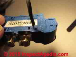
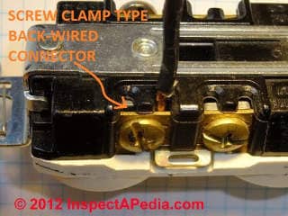
At BACK-WIRED ELECTRICAL DEVICES we describe three common methods (and a fourth less-common back-wire only method) of connecting electrical wires to electrical receptacles ("outlets") and switches. Here is a recap of the three connector types:
- Push-in back-wired connectors using an internal spring-clip inside the device
[Click to enlarge any image]
- Screw-Clamp connectors that permit connecting of wires through the back of the device
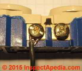
- Binding-head screw connectors that secure a wire wrapped around the screw shaft between the under-side of the screw and a mating connecting surface on the device.
The first two of these electrical wire connectors are popular because of the speed and ease of making the connection. The third, the binding head screw can accept either a straight wire, making it similar to the screw-clamp connector, or a wire can be wrapped around the screw after which the screw is tightened using a hand or power screwdriver.
While opinions may vary, field failure reports that seem to occur principally among push-in backwired electrical devices as well as objective measurements suggest that the safety, performance, and reliability of these three connector types varies considerably.
In particular, the bulk or gross-level size of physical contact area size between the wire and the connector as well as the clamping force of the connector against the wire are very different among these three choices.
The connection quality and reliability varies accordingly. Low contact force between the wire and the receptacle connector where spring-type push-in backwired terminals are used on receptacles is probably the most significant reason that these connections can be expected to deteriorate over many years, but the contact area size also varies considerably.
Summary of Wire to Connector Contact Area Size & Clamping Force for Electrical Receptacles
These conclusions are based on supporting details for these wire to receptacle connector service life performance estimates are in the two articles linked in the text below.
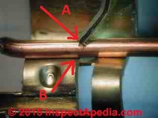
From the summary table at RECEPTACLE WIRE-TO-CONNECTOR CONTACT AREA SIZES we have these contact area sizes:
- Push in backwire spring connector contact area CA if the wire is "straight"
0.8875 mm2 - Push in backwire connector CA for a curved or bent wire
0.3875 mm2 - Clamp type screw connector CA on a relatively straight wire inserted into the clamp
1.8 mm2 - Binding head screw connector CA for a wire wrapped nearly 360 degrees under the screw
3.68 mm2
The ratio of best case (straight wire, looped under a binding head screw) to worst case (bent wire under a spring clip) the contact area ratio is
- Contact area ratio:
3.68/ 0.3875 = a ratio of about 10 x, that is the binding head screw gives about ten times more area than a not-straight wire inserted into a push-in backwired spring-clip connector.
Next, from WIRE-TO-CONNECTOR FORCE COMPARISONS Aronstein reports a 75x difference in clamping pressure or force between spring clip and screw connector, where the screw connector exerts the much greater force.
In that article we state that
Contact Resistance is a function of (force x micro-contact points x other factors such as oxide resistance)
Ignoring other factors that remain the same among these connector design differences (or differences that we are not considering such as resistance to mechanical disturbance)
- Contact clamping force ratio: There is of the order of 75x greater actual clamping force at a duplex receptacle wire termination at a screw terminal than in a push-in terminal of the types so far examined.
To compare overall contact quality of a spring clamp backwired device with a binding head screw connector, we multiply these two factors (ratio of differences in contact area x ratio of differences in clamping force) together to claim that comparing best to worst case among the connections examined,
- Theoretical Performance for wires that are not straight (under the spring clip or wrapped under a binding head screw)
For a "bent" or not straight" electrical wire we have 3.68/03.875 = 10 Contact area size ratio x 75 Clamping force ratio or 750 times better contact (pressure x bulk area) with a binding head screw connector than with a spring clip connector on a bent wire, - Theoretical Performance for wires that are straight (under the spring clip or wrapped under a binding head screw)
For a 'straight wire" we have 3.68/0.8875 = 4 Contact area size ratio x 75 Clamping force ratio or about 300 times better contact connection with a binding head screw connector than with a spring connector
assuming that all other features such as wire and contact smoothness that would affect micro-level contacts are equal.
Note 1: while my estimate of the area of round wire surface in contact with a flat surface (x length of wire) is a guess at the width of round wire actually touching at the tangential point of contact with the flat surface (0.1mm), that doesn't matter nor does it change these ratios since I use the same wire surface contact width in all cases. It's the varying lengths of the bulk contact areas that I'm comparing.
Note 2: the quantitative analysis given above is for purposes of demonstrating relative differences among different electrical connectors and does not attempt to represent the exact function that would describe the precise product of connector clamping force and contact area as a means of comparing electrical devices.
The actual relationship may be more complex and might require measuring other forces such as electrical resistance and mechanical motion as well as a tabulation of force with contact area combined with numerical analysis that is beyond the scope of this article.
Electrical Wire to Receptacle Connection Quality Conclusions
OPINION:
- Binding head screw vs. spring clip backwire connector:
For electrical receptacles and switches that offer a choice of using a push-in type spring-clip backwire connector and using a binding head screw connector to connect a No. 14 copper wire to the device, the overall quality and thus long term reliability of the electrical connection made by the combined effects of contact area (wire to connector) and contact force (wire to connector) under a binding head screw is between a maximum of 300x (straight wire) and 750x (wire not straight) better than that obtained using the push-in spring-clip connector.
A wire wrapped around the screw shaft and tightened under a binding head screw gives the most-reliable electrical connection at an electrical receptacle or switch.
The actual benefit of using wire wrapped under a binding-head screw will be less than the theoretical maximum because the wire under the screw will never form a perfect 360 degree circle when applied in the field. However the relative contact area x clamping force differences among these connectors remains dramatic for all cases. - Pressure plate screw vs. spring clip backwire connector:
For electrical receptacles and switches that offer a choice of using a push-in type spring-clip backwire connector and using a pressure-plate screw connector, other constraints kept as in the case above, the pressure plate screw connection is between 150x (straight wire) and 200x (wire not straight) likely to be more reliable in long term use.
Overall, the binding-head screw offers the best electrical wire connection quality and long term reliability, all other features being equal, because it offers the greatest bulk surface contact area and significantly-higher contact pressure. The pressure-plate connector is also likely to perform significantly better than the spring-clip connector. - Back-wiring best choice:
Electrical workers installing receptacles and switches who want to back-wire a device will be selecting the more-reliable connector using the back-wired screw-clamp connector than a push-in spring clip connector.
Inserting a straight wire end into a screw-clamp connector gives more contact surface than inserting a straight wire end beneath a binding head screw, but either of these connections is probably more reliable than using a back-wired push-in spring clip connector because the screw exerts much greater clamping force than a spring-clip connector. - Best choice in electrical connections at a receptacle or switch:
Electrical workers installing receptacles and switches who want the most-reliable connector should wrap the wire under a binding head screw. - Long term vs. short term performance & mechanical disturbance:
These are electrical connection performance estimates are for the service life of the connector and do not predict short term performance nor do they address differences in the vulnerability of these wire connection types to mechanical or environmental disturbances.
However it is apparent that a wire held in place by either of the two types of screw connectors is likely to be more secure against mechanical disturbance than wires held by the spring clip connector - an effect that we have not quantified.
InspectAPedia is supported by ads placed on our pages by Google. InspectAPedia tolerates no conflicts of interest. We have no relationship with advertisers, products, or services discussed at this website.
Aronstein Comments:
Dan:
The actual metallic conducting area together with the mechanical resistance to motion at the contact interfaces strongly influence the life of a wire termination. For terminations in the permanent electrical power circuits in our homes, the safe life is the time in the expected range of normal service conditions before some samples start to heat abnormally.
Connections with relatively tiny metallic areas of contact and which are susceptible to motion at the contact surfaces may initially provide low resistance, but they are more likely to fail after some years in service. They cannot be depended on to provide the type of permanent connection that is required for long-term safety in buildings.
What your engineers interested in this matter need to do next is some life testing under actual service conditions to determine the relative life of a low-force contact vs. a high force contact.
All other things being equal, they will find that higher contact force yields longer life.
The field failures and the long-term test results provide the most persuasive evidence that push-in backwired receptacle wiring connections are not suitable for the permanent wiring system in homes. The performance of the older generation of back-wired push-in receptacles was poor, leading to limiting the size of wire that could be inserted to #14, reducing the number of wiring openings, and changing or eliminating the wire release features.
It is yet to be seen whether today's push-in wire termination types are sufficiently improved to provide the required low resistance performance over the long-term in actual installations. I do not want my home to be part of that experiment. What is crystal clear is that the binding-head screw termination is vastly superior to the push-in terminations, and that's what I would want - and what I have - in my home. - Jess Aronstein
Shields Comments
Contact force and contact area most likely have limits of benefit to both mechanical resistance of motion and electrical resistance.
The limits are likely to be a function of each parameter. I have not conducted tests to determine the nature of the limits and whether they occur within the range of actual contact areas and forces afforded by these connectors. If there is credible evidence of significant receptor malfunction or testing that raised question of malfunction I would expect a receptacle manufacturer would want to provide in-house data to support its product. - Lee Shields
References
- Aronstein, Jess, [Personal communication, J.A. to the editor (Daniel Friedman)], 9 December 2015. Dr. Jess Aronstein, protune@aol.com is a research consultant and an electrical engineer in Schenectady, NY. Dr. Aronstein provides forensic engineering services and independent laboratory testing for various agencies. Dr. Aronstein has published widely on and has designed and conducted tests on aluminum wiring failures, Federal Pacific Stab-Lok electrical equipment, and numerous electrical products and hazards.
See ALUMINUM WIRING BIBLIOGRAPHY and FPE HAZARD ARTICLES, STUDIESand also BACK-WIRED ELECTRICAL DEVICES for examples. Dr. Aronstein is a frequent contributor to InspectApedia.com and a personal friend of the publisher/editor. His contact information is at TECHNICAL REVIEW COMMITTEE MEMBERS - Aronstein, J. "Evaluation of receptacle connections and contacts." In Electrical Contacts, 1993., Proceedings of the Thirty-Ninth IEEE Holm Conference on, pp. 253-260. IEEE, 1993.
Abstract:
Wire connections and plug contacts at receptacles account for the majority of electrical power contacts in most residential structures. Average current and duty cycle for these wiring devices have been increasing over the past decades as more appliances, portable heating equipment, and electronics are added to typical user loading.
Receptacle contact and connection failures contribute significantly to fire losses in the United States. This paper provides comparative data on long-term test performance of copper-wired screw and push-in wiring terminals and on insertion plug contacts of receptacles presently on the market. - Babu SS, Santella ML, Feng Z, Riemer BW, Cohron JW. Empirical model of effects of pressure and temperature on electrical contact resistance of metals. Science and Technology of Welding & Joining. 2001 Jun 1;6(3):126-32.
Abstract
An important input property in the development of process models for resistance spot welding is electrical contact resistance. A model for the pressure and temperature dependence of electrical contact resistance was developed from established concepts of contact resistance. The key to developing the desired relationship is determining surface roughness characteristics, which is experimentally problematic.
To overcome this difficulty the electrical resistance of contacting interfaces was measured as a function of the pressure applied across the interfaces. Using known information about the temperature dependence of bulk resistivity and mechanical properties, a curve fitting procedure was used to establish the desired relationship of contact resistance to pressure and temperature.
This empirical model agrees well with experimental measurements in the regime of low applied pressure. At high pressures, predictions underestimate contact resistance, and this was attributed to strain hardening of asperities at the contacting interface.
The model also predicts that the competing effects of bulk resistance and contact resistance will produce a peak in the variation of contact resistance with temperature. The model provides a suitable means for incorporating the pressure and temperature dependence of contact resistance into process models of the resistance spot welding process. - Barber, J. R. "Bounds on the electrical resistance between contacting elastic rough bodies." In Proceedings of the Royal Society of London A: Mathematical, Physical and Engineering Sciences, vol. 459, no. 2029, pp. 53-66. The Royal Society, 2003.
Abstract:
A method is developed for placing bounds on the electrical contact conductance between contacting elastic bodies with rough surfaces. An analogy is first established between contact conductance and the incremental stiffness in the mechanical contact problem.
Results from contact mechanics and the reciprocal theorem are then used to bracket the mechanical load–displacement curve between those for two related smooth contact problems. This enable bounds to be placed on the incremental stiffness and hence on the electrical conductance for the rough contact problem.
The method is illustrated by two simple examples, but its greatest potential probably lies in establishing the maximum effect of neglected microscales of roughness in a solution of the contact problem for bodies with multiscale or fractal roughness. - Timsit, Roland S. "Electrical contact resistance: properties of stationary interfaces." In Electrical Contacts, 1998. Proceedings of the Forty-Fourth IEEE Holm Conference on, pp. 1-19. IEEE, 1998.
The paper reviews the dependence of electrical contact resistance on the shape and dimensions of /spl alpha/-spots and on the magnitude of the mechanical contact load. The range of validity of the classical voltage-temperature relation for electrical contacts is also examined. The paper describes experimental evidence of breakdown of the classical electrical theory when /spl alpha/-spots become too small.
One of the interesting and useful properties of relatively small /spl alpha/-spots is that they are subject to large surface stresses. These stresses induce /spl alpha/-spot growth.
...
Continue reading at BACK-WIRED ELECTRICAL DEVICES - home or select a topic from the closely-related articles below, or see the complete ARTICLE INDEX.
Or see these
Recommended Articles
- BACK-WIRED ELECTRICAL DEVICES - home
- BACKWIRED RECEPTACLE FAILURE PHOTOS
- BACKWIRED RECEPTACLE FAILURE REPORT
- BACK-WIRING FAQs for RECPTACLES & SWITCHES
- ELECTRICAL OUTLET, HOW TO ADD & WIRE - home - for general wiring procedures, connections & advice for connecting electrical receptacles.
- RECEPTACLE WIRE-TO-CONNECTOR CONTACT AREA SIZES
- WIRE-TO-CONNECTOR FORCE COMPARISONS
- WIRE-TO-CONNECTOR PERFORMANCE SUMMARY
Suggested citation for this web page
WIRE-TO-CONNECTOR PERFORMANCE SUMMARY at InspectApedia.com - online encyclopedia of building & environmental inspection, testing, diagnosis, repair, & problem prevention advice.
Or see this
INDEX to RELATED ARTICLES: ARTICLE INDEX to ELECTRICAL INSPECTION & TESTING
Or use the SEARCH BOX found below to Ask a Question or Search InspectApedia
Ask a Question or Search InspectApedia
Questions & answers or comments about how to install and wire electrical outlets or receptacles in buildings.
Try the search box just below, or if you prefer, post a question or comment in the Comments box below and we will respond promptly.
Search the InspectApedia website
Note: appearance of your Comment below may be delayed: if your comment contains an image, photograph, web link, or text that looks to the software as if it might be a web link, your posting will appear after it has been approved by a moderator. Apologies for the delay.
Only one image can be added per comment but you can post as many comments, and therefore images, as you like.
You will not receive a notification when a response to your question has been posted.
Please bookmark this page to make it easy for you to check back for our response.
IF above you see "Comment Form is loading comments..." then COMMENT BOX - countable.ca / bawkbox.com IS NOT WORKING.
In any case you are welcome to send an email directly to us at InspectApedia.com at editor@inspectApedia.com
We'll reply to you directly. Please help us help you by noting, in your email, the URL of the InspectApedia page where you wanted to comment.
Citations & References
In addition to any citations in the article above, a full list is available on request.
- Timothy Hemm has provided photographs of various electrical defects used at the InspectAPedia TM Website. Mr. Hemm is a professional electrical inspector in Yucala, CA.
- Mark Cramer Inspection Services Mark Cramer, Tampa Florida, Mr. Cramer is a past president of ASHI, the American Society of Home Inspectors and is a Florida home inspector and home inspection educator. Mr. Cramer serves on the ASHI Home Inspection Standards. Contact Mark Cramer at: 727-595-4211 mark@BestTampaInspector.com
- John Cranor [Website: /www.house-whisperer.com ] is an ASHI member and a home inspector (The House Whisperer) is located in Glen Allen, VA 23060. He is also a contributor to InspectApedia.com in several technical areas such as plumbing and appliances (dryer vents). Contact Mr. Cranor at 804-873-8534 or by Email: johncranor@verizon.net
- [3] NFPA - the National Fire Protection Association can be found online at www.nfpa.org
- [4] The NEC National Electrical Code (ISBN 978-0877657903) - NFPA might provide Online Access but you'll need to sign in as a professional or as a visitor)
- US NEC Free Access: See up.codes at this link: https://up.codes/code/nfpa-70-national-electrical-code-2020
- [5] Special thanks to our reader Steve who pointed out prior errors in our illustrations.
- [6] Simpson Strong-Tie, "Code Compliant Repair and Protection Guide for the Installation of Utilities in Wood Frame Construction", web search 5/21/12, original source strongtie.com/ftp/fliers/F-REPRPROTECT09.pdf, [copy on file as /Structures/Framing/Simpson_Framing_Protectors.pdf ]. "The information in this guide is a summary of requirements from the 2003, 2006 and 2009 International Residential Code (IRC), International Building Code (IBC), International Plumbing Code (IPC), International Mechanical Code (IMC), 2006 Uniform Plumbing Code (UPC) and the 2005 National Electrical Code."
- "Electrical System Inspection Basics," Richard C. Wolcott, ASHI 8th Annual Education Conference, Boston 1985.
- "Simplified Electrical Wiring," Sears, Roebuck and Co., 15705 (F5428) Rev. 4-77 1977 [Lots of sketches of older-type service panels.]
- "How to plan and install electric wiring for homes, farms, garages, shops," Montgomery Ward Co., 83-850.
- "Simplified Electrical Wiring," Sears, Roebuck and Co., 15705 (F5428) Rev. 4-77 1977 [Lots of sketches of older-type service panels.]
- "Home Wiring Inspection," Roswell W. Ard, Rodale's New Shelter, July/August, 1985 p. 35-40.
- "Evaluating Wiring in Older Minnesota Homes," Agricultural Extension Service, University of Minnesota, St. Paul, Minnesota 55108.
- "Electrical Systems," A Training Manual for Home Inspectors, Alfred L. Alk, American Society of Home Inspectors (ASHI), 1987, available from ASHI. [DF NOTE: I do NOT recommend this obsolete publication, though it was cited in the original Journal article as it contains unsafe inaccuracies]
- "Basic Housing Inspection," US DHEW, S352.75 U48, p.144, out of print, but is available in most state libraries.
- In addition to citations & references found in this article, see the research citations given at the end of the related articles found at our suggested
CONTINUE READING or RECOMMENDED ARTICLES.
- Carson, Dunlop & Associates Ltd., 120 Carlton Street Suite 407, Toronto ON M5A 4K2. Tel: (416) 964-9415 1-800-268-7070 Email: info@carsondunlop.com. Alan Carson is a past president of ASHI, the American Society of Home Inspectors.
Thanks to Alan Carson and Bob Dunlop, for permission for InspectAPedia to use text excerpts from The HOME REFERENCE BOOK - the Encyclopedia of Homes and to use illustrations from The ILLUSTRATED HOME .
Carson Dunlop Associates provides extensive home inspection education and report writing material. In gratitude we provide links to tsome Carson Dunlop Associates products and services.


