
InspectAPedia®FREE Encyclopedia of Building & Environmental Construction, Diagnosis, Maintenance & Repair |
Question? Just ask us! InspectAPedia
|
 Splicing Wires When Installing Electrical Receptacles
How to splice, connect, or extend electrical wires when installing an electrical plug outlet or wall plug
- POST a QUESTION or COMMENT about how to install and wire electrical outlets or receptacles in buildings.
How to splice or extend wires as needed when wiring up an electrical receptacle (wall plug or outlet).
When wiring electrical circuits in a building it may be necessary to join or extend wires using a mechanical splice.
Here we discuss splices commonly made when wiring electrical receptacles (wall plugs or outlets) and switches.
We give specific examples of problems and solutions run into by our readers or by the author during electrical wiring updates and addiitions - Daniel Friedman.
InspectAPedia tolerates no conflicts of interest. We have no relationship with advertisers, products, or services discussed at this website.
- Daniel Friedman, Publisher/Editor/Author - See WHO ARE WE?
Electrical Wire Splices When Adding a Receptacle
- Splices and other wire connections:
In the electrical circuit, these must be made properly to be secure and protected against short circuit in the electrical panel, in any junction boxes used for splices, and at the electrical receptacle (discussed more below). - Back-wired electrical receptacles:
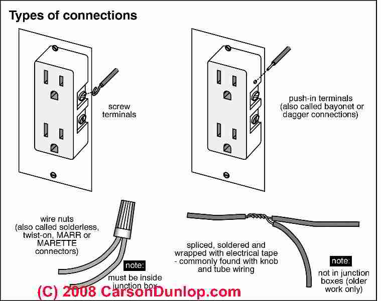
Although this sketch, courtesy of Carson Dunlop Associates, shows push-in type terminals used on some electrical switches and receptacles (upper right in the sketch), and although those connections are legal, we don't trust them and we don't use them.
That's because the push-in terminals on some electrical outlets and switches are less reliable than the side screw terminals.
Studies have shown (Aronstein) that back-wired electrical receptacles whose wires are simply pushed into a round hole at the back of the receptacle have a very small contact area between the receptacle and the wire (just the very edge of a flat spring), and that this contact can be damaged, especially if the receptacle is re-used.
Watch out: On older versions of push-in terminals the hole for the wire would admit a #14 or a larger #12 wire.
If an outlet was first wired with a #12 wire (which bends the contact spring farther open) and later re-wired to a #14 wire, the connection was particularly unreliable.
Some if not all newer electrical outlets with push-in terminals have been modified to use only the smaller #14 sized wire opening to prevent this failure. But we still prefer the increased contact area and increased contact security that comes from being able to tighten a screw.
A screw-terminal (upper left in the sketch) is a more reliable connection for wiring at an electrical outlet.
Some newer electrical outlets have a back-wire push-in type terminal which uses a screw to securely pinch the wire in the receptacle - these are fine. The splice at lower left in the sketch depicts using a twist-on connector - the right way to make a wire splice inside of an electrical junction box.
See more electrical wiring splice instruction details at ELECTRICAL SPLICES, HOW TO MAKE
Use Splices Inside of an Electrical Box to Add Wire Lengths when Moving / Adding Receptacles
Using Dave's question below we explain the issues of space, electrcial code compliance, and solutiosn when you need to add wire length to permit moving or adding electrical receptacles ("wall plugs") in an existing structure.
Need to Move Electrical Receptacles but Wires are Too Short
I recently moved into a 3 1/4 story home, and I have a basement that I am trying to finish with drywall. The room is down to the studs and the electrical receptacles are about 4' up the wall.
The Romex wiring is stapled, and there isn't enough wire to lower them.
It is way to much work for me to replace all of the downstairs wiring right to the breaker box, so I'm wondering if it is possible to add onto the existing wires and attach wire screws or marrets within the walls before I start adding drywall, or whether I should add some kind of junction box to contain the marreted wires in between.
My building code stipulations would differ in some cases because I live in Canada, but I just want to do the job right, and I do not want to take the chance of having any fire hazards, as I also have small children. - Dave 2/10/12
Reply: if you have to move an entire string of electrical receptacles complete re-wiring is faster and cheaper than adding a splice box for every device.
Dave,. you are correct to be careful about moving outlets or any other device when the existing wires are too short. The temptation is to just splice on an extension and bury that in the wall or ceiling: an illegal, improper, unsafe as well as really aggravating approach.
The proper approach is to add a junction box at each splice - we never splice 120/240V wires without including them in a box. You can reduce the wiring work a little by using plastic boxes instead of steel - avoiding having to also connect the box to the ground wire.
The proper approach also means that you don't then bury any of these splice-boxes in the walls either. Each box has to be brought to the surface and covered.
The result is a lot of work and expense and an ugly wall with an extra junction box and blind cover all along the wall over each of the now moved or lowered electrical receptacles.
Frankly I figure that especially as you've already got the wall open to the studs, if there are more than one or two receptacles to be moved you'll probably find it is actually much less total work to re-wire the entire circuit, allowing proper lengths of wires for each box.
You might carefully remove and re-route the existing wire lower in the wall or you might buy all new electrical wire - depending on the age and condition of the existing materials.
Watch out: when removing wire that appears to be in good condition, if you nick the insulation you've created a new hazard.
How to Use Pigtail Splices to Join Multiple Hot, Neutral or Ground Wires
Reader Question: Can I connect a pigtail from multiple hot, neutral, or ground wires over to a receptacle
I have 2 receptacles that are both side and back wired, 3 hot and 3 neutral wires. I eliminated one receptacle (capping the 3 wires together) but want to keep the other. Is it safe to just run a pigtail from the 3 wires to the receptacle? - Greg
When wiring multiple boxes in series, how do you connect both incoming and outgoing ground wires to the back of the receptacle? With 12 ga. wire, only one wire will fit under the green screw (and not very tightly, at that - there's no washer or clamp.) - Bob M.
Reply:
Yes, Greg, that's a common practice. Be sure that your junction box is big enough to contain all of the wires and twist-on connectors.
Bob, similar to Greg's question, I see two approaches to hooking up the ground wire in junction boxes and at electrical receptacles.
- If the incoming ground wire from the feed circuit was left long enough,
it can be run continuously, connected to a grounding screw that connects the wire to the metal junction box (skip this step if plastic junction boxes are in use), on to the ground screw terminal at each electrical receptacle, and ending with a ground clamp crimp connector that ties the incoming ground to the ground wire of the outgoing wire that continues to the next junction box.
- If the incoming ground wire is not long enough to run as above,
then an additional length of ground wire is pigtailed to the incoming ground and makes the other connections I've described above.In sum, all of the grounds are tied together in the box: the incoming ground, outgoing ground, and ground wires to each of the electrical receptacles.
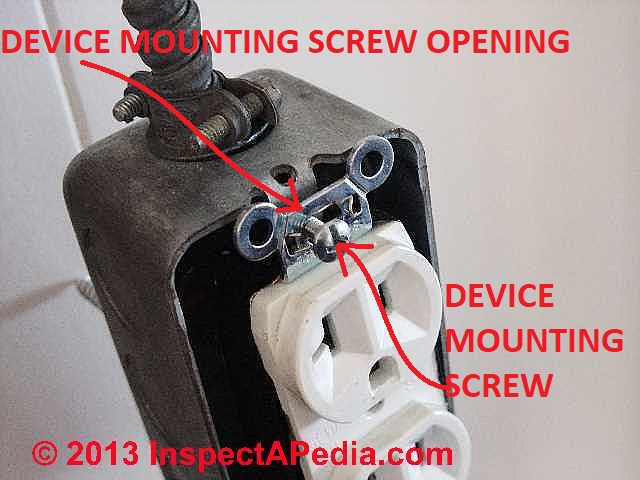
Watch out: while the electrical receptacle ground may also be electrically connected to the metal strap that mounts the receptacle to the junction box (photo at left), and while the junction box may be metal, do not rely on the receptacle mounting screws and receptacle strap-to-box contact to serve as the grounding connection.
It's easy for the receptacle mounting screws to be deliberately left loose or to work loose - making that ground connection unreliable. Use a ground wire.
Connecting Wires of Different Sizes: e.g. Connecting 14-3 to 14-2 wires & to the junction box
How do you connect 14-3 to 14-2 to a junction box - Moe.
DF Reply:
Moe, twist on connectors are used to connect the incoming and outgoing hot, neutral, and ground wires, and a single pigtail length in that same twist-on connector can connect the ground to the local junction box.
Watch out: when mixing 14-3 and 14-2 wires on an electrical circuit.
If the 14-3 wires are the hot wires entering the box, and if only 14-2 is leaving the junction box, cap off the unused (typically the red) hot lead.
Do not just bond it together with the outgoing hot wire in the 14-2 group. Making that mistake would short two hot leads together, would be improper, unsafe, and a fire or shock risk.
Details about how to wire up an electrical receptacle are at ELECTRICAL RECEPTACLE CONNECTION DETAILS - where to connect black, white, red, green, ground wires .
This article series describes how to choose, locate, and wire an electrical receptacle in a home. Electrical receptacles (also called electrical outlets or "plugs" or "sockets") are simple devices that are easy to install, but there are details to get right if you want to be safe.
How do I install multiple electrical outlets (receptacles) along a wall?
Putting in more than outlet on along a 12ft wall - Mike Tucker
DF Reply:
Mike, if your comment is a question of how to put in more than one outlet along a 12 foot wall, yes it's perfectly permitted to exceed the minimum number of receptacles along a wall.
The wiring system is unchanged except that in some cases I recommend installing two different circuits and alternating which outlet is served by which circuit. That avoids overloading one circuit if you are plugging in lots of devices in one area.
Can I add one more outlet onto an existing string?
I have an existing outlet being used for lamps I wanna run one more outlet shares from the hot on is it okay? - Phantum 113 8/1/12
DF Reply:
Phantum:
Usually, yes provided all safe and proper wiring code procedures are followed.
If the circuit is overloaded already, no.
If the circuit is knob and tube wiring, no - we don't extend knob and tube.
How do I hook up two receptacles from a single line pair
I’m attempting to wire two separate receptacles from one (line) wire, not in-line one after the other but effectively as a “Y” from a junction box with two load lines out (one to a north wall receptacle and the other to a south wall receptacle in my barn).
Using screw-on connectors, I connected the three black wires together; the three white wires together; and the three green wires to a pigtail screwed into the junction box. One receptacle works fine, but plugging anything into the other receptacle trips the circuit breaker.
If this is not the correct wiring configuration within the junction box, what is the solution? - Robert 8/9/12
Mod Reply:
Robert:
I agree that you've got a miswired connection and it sounds like a short somewhere, but no way can nor should someone risk killing you by pretending we can see what you did.There are plenty of possible snafus, such as overtightening a wire clamp that cuts into and shorts a wire.
That's what I found when I was called on to figure out why the GFCI circuit breaker kept tripping in a New York City apartment wired by my brother-in-law Matt - a theatre electrician.
Reader follow-up:
Thanks Mr. Friedman,
Turns out the over tightened wire clamp cutting into a wire was the problem.
Reader Comments, Questions & Answers About The Article Above
Below you will find questions and answers previously posted on this page at its page bottom reader comment box.
Reader Q&A - also see RECOMMENDED ARTICLES & FAQs
On 2024-04-29 by Upstate - What’s the best way to splice in 10ft of 8/2 wire?
I have an 8/2 AWG NMB stranded wire that's probably around 80ft long running from an outdoor AC compressor to my panel. 2-pole 40Amp breaker. The wire was run diagonally across a basement and structural beams and it needs to take a different longer path in the exposed area of the run so is now about 10ft short of the panel.
The unexposed section of the wire's route precludes replacing the whole wire without significant grief and expense.
The question is: What’s the best way to splice in 10ft of 8/2 wire?
Having an accessible junction box at the splice is a given but what about the spice itself? Large wire nuts or butt splicing with mechanical crimped connectors seem to be methods within the code but technically speaking I would be more confident in a mechanical PLUS soldered connection. It seems there are specialty crimp-and-heat-to-melt-solder connectors but I don’t imagine regular electricians use them.
While I’m at it, it seems that the NEC has a GFCI exception for HVAC equipment that expires in 2026 so should I replace the breaker with a GFCI?
By InspectApedia Publisher - a too-small connector can become unreliable and maybe risks a short or shock
@Upstate,
I certainly have seen some unreliable wire splices when someone tried to use a too-small connector on larger gauge wires. The connection becomes unreliable and maybe risks a short or shock.
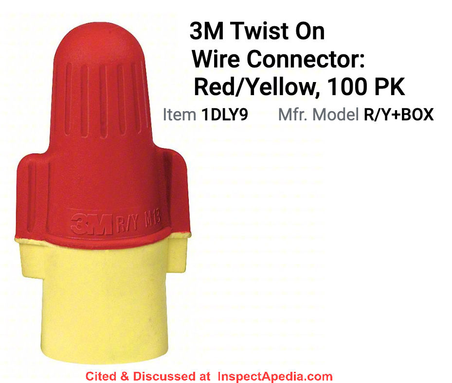
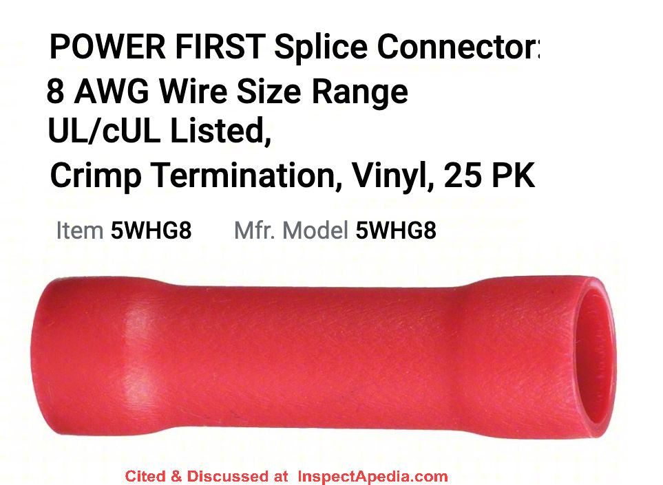
There are both crimp-on connectors and twist -on connectors sized to accept 2 #8 multi-strand copper wires; I'll show two examples here.
I like soldering connections too. I think if you don't make your solder blob too big, you can first slide a crimp connector over one of the wires, push it down out of the way, solder the two wires together, and slide it back and crimp it in place as an insulator.
The downside of this approach in my OPINION is that you're soldering two wires in parallel - your solder job better be perfect - as opposed to making a mechanical connection by using a twist-on connector or a lug.
Of course if you used a lug you've got to tape it and you'll want a deeper junction box. ,
3M makes a twist on connector sized for #8 wire and that could thus cap and hold a pair of wires twisted together. This, too, will be a bit bulkier than the first option above.
I haven't read 3M's instructions - which we both should do - but I would be less confident about twisting such a connector on over a soldered joint.
About GFCIs on HVAC circuits, it's just an OPINON but if you're working on the circuit now, it makes sense to go a head and make it compliant with the code change coming up - that you cited. And thanks for mentioning it.
For other readers: Note that the exception expiration mentioned by Upstate is described as tentative:
Tentative Interim Amendment (TIA) 1653 refers to NEC 210.8(F) GFCI Protection for Outdoor Outlets.
The amendment issued for the 2020 NEC® makes this new exception
Exception 2: “Exception No. 2: Ground-fault circuit-interrupter protection shall not be required for listed HVAC equipment. This exception shall expire September 1, 2026”.
So yeah, after September 1 2026 an outdoor outlet for HVAC equipment gets a GFCI.
Here's the Twist-On I was discussing
Any electrical supplier has connectors for #8 wire and they're also sold by online vendors such as Grainger, but in the online case you may find vendors trying to get you to buy a box of 500 when you only want 2 connectors.
On 2024-04-30 by Upstate
@InspectApedia Publisher,
Thanks for all the details.
Practically speaking solder would probably make no difference mechanically (it's not strong) and in this situation I've reassured myself that there is minimal voltage drop over a 90-100ft 8AWG wire. The NEC is "no more than 10% voltage drop" which by my estimate is more like 500-1,000ft.
I do wonder about WAGO, IDEAL and other push-type connectors but the mechanics and resistance of twisting an insulated twist-on connector in a box seems better. Of course it needs to be twisted carefully to maximize contact while retaining the copper strength.By InspectApedia Publisher
@Upstate,
Frankly, I agree with you, particularly for an indoor wire installation such as the one we are discussing
Where I've been comfortable using crimp connectors for decades has been an automotive wiring.
And having inspected some number of electrical failures along with a forensic expert, often I've seen that the underlying cause of failure was improper wire prep for lack of care and actually making the connection a secure one.
Workmanship certainly counts.
On 2021-11-20 by Mark - How to turn an appliance with a plug into a hard wired connection in a outlet box
What is the method to turn an appliance with a plug (in this case a heated towel rail) into a hard wired connection in a outlet box..... seeing as code does not allow cord behind drywall?
By Inspectapedia Com Moderator
@Mark,
I'll be glad to address your question but first help me understand it correctly.
Are you asking about rotating in place the position an appliance or are you asking how to turn off an appliance that doesn't have an on-off switch?
About "cord behind drywall" that's exactly right: we never run zip cord or lamp cord or any extension cord or appliance connection cord through building walls or ceilings or floors because the wire is not rated, approved, nor safe to be used in those locations. The risk is a fire or shock hazard.
But certainly it's entirely possible to add an electrical receptacle where one is needed for convenience, by using proper electrical wiring, boxes, devices, etc.On 2021-11-21 by Mark
@Inspectapedia Com Moderator,
Hi the appliance is a wall mounted heated towel rail that has a cord with 3-prong plug.
I want to cut of plug and hard wire to a wall switch but unsure how I take the cord into the switch box.
Was thinking using a blank plate with a hole and grommet to splice to romex and into the switch box. But unsure if meets code.By Inspectapedia Com Moderator
@Mark,
One approach which would certainly meet the electrical code would be to leave the wall receptacle as a standard one and leave the line cord on modified with a standard plug on the end.
Simply rewire that particular wall receptacle to be operated by a wall switch.
Then you can simply plug in the heater you described just as you would normally, and you still can control it, turning on and off, by the wall switch.
Essentially you are installing a switched electrical receptacle. which is a common electrical practice and uses normal electrical wiring, switch, receptacle, and electrical boxes.On 2021-11-21 by Mark
@Inspectapedia Com Moderator,
Trying to get rid of 6ft cord and a neater installationBy Inspectapedia Com Moderator - never use line cord or extension cord as building in-wall or in-ceiling wiring
@Mark,
Here's a stumbling point:
Your project sounds like wiring a new overhead light fixture: twist on connectors in the electrical box join the light's wires to the circuit wires.
But it's not the same. Those light fixture wires are designed for connection to a circuit wire and are entirely enclosed inside of the fixture and inside the electrical box. They're not run out "in the air" between the light and the electrical box.
Line cords like the one on your heater, ending in a wall plug, are flexible and rated/intended to be used outside of building wall and ceiling cavities to connect the appliance to a wall receptacle.
That wire is not safe to run inside of a building cavity and isn't approved to do so. I'm also worried that if you tried to wire the cord direct to the wall receptacle or direct into an electrical box you'll not only violate the electrical code (U.S. NEC) but it could actually be unsafe.
You can, of course, replace a line cord with a shorter one using listed appliance wire or simply cut off the wall plug and shorten the wire and connect the wire to a listed replacement wall plug.
What I'm reluctant to do is try to run appliance cord actually into an electrical box. It's mechanically easy of course but isn't approved.
NEC 314.17 Conductors Entering Boxes, Conduit Bodies, or Fittings.
Conductors entering boxes, conduit bodies, or fittings shall be protected from abrasion and shall comply with 314.17(A) through (D).
(C) Nonmetallic Boxes and Conduit Bodies. Nonmetallic boxes and conduit bodies shall be suitable for the lowest temperature-rated conductor entering the box. Where nonmetallic sheathed cable or multi-conductor Type UF cable is used, the sheath shall extend not less than 6 mm (1⁄4 in.) inside the box and beyond any cable clamp. In all instances, all permitted wiring methods shall be secured to the boxes.
Exception: Where nonmetallic-sheathed cable or multi-conductor Type UF cable is used with single gang boxes not larger than a nominal size 57 mm × 100 mm (21⁄4 in. × 4 in.) mounted in walls or ceilings, and where the cable is fastened within 200 mm (8 in.) of the box measured along the sheath and where the sheath extends through a cable knockout not less than 6 mm (1⁄4 in.), securing the cable to the box shall not be required.
Multiple cable entries shall be permitted in a single cable knockout opening
On 2021-11-05 by Anonymous - which wire to put the ground with, black or white?
which wire to put the ground with, black or white?
On 2021-11-05 by Inspectapedia Com Moderator - neither one!
@Anonymous,
Neither one.
In a typical electrical circuit the black wire is hot the white wire is neutral and the ground wire is a separate conduct or, sometimes green or bare.
Watch out: if you are unfamiliar with proper and safe electrical wiring you should consider that you can be shocked or killed.
On 2020-02-03 by Donna Garcia - was it safe to add wall plugs from an attic wire above?
I live in a Housing Authority and there aren't many plug ins. The man 4 doors down went into the attic and spliced into a wire to add a plug . Is this dangerous?
On 2020-02-03 by danjoefriedman (mod) - possibly not safe
Donna
It certainly could be dangerous
1. if the work was not done properly, then there is a risk of a short, shock, or fire
It may also be inconvenient
2. if now the circuit is overloaded and people keep blowing fuses or tripping circuit breakers
Watch out: if you're not trained in proper and safe electrical wiring the risks are fire, shock, injury or even death. But of course from here in Mexico we can't see your wiring installation nor know if it's safe or not.
Where you live, however, it may be that electrical work must be done by a licensed electrician.
On 2018-07-23 by Barry - is it ok to eliminate one outlet in a string of them?
i have 5 outlets running on one line in the same wall from my bedroom to my kitchen in an older mobile home.can i eliminate one outlet cap the existing wires together,w/ w, b/b, g/g, and still get power to the other outlets?
On 2018-07-23 by danjoefriedman (mod) - yes but watch out for code violation on outlet spacing
Yes. That is, it's technically possible to eliminate one of the receptacles and simply connect the wires to continue to feed the remaining ones "downstream" from the one you removed.
ButWatch out: there are electrical code, safety, and convenience reasons that codes require electrical redeptacles to be readily accessible and that no receptacle be more than 6 ft. away along walls. So if you eliminate an "outlet" ("receptacle" by proper terminology) along a wall you may force later occupants to make unsafe use of extension cords and you may be violating the electrical code.
Watch out: if you're not trained in electrical wiring, if you make a mistake you can burn the place down or shock or kill someone.
...
Continue reading at STRIPPING ELECTRICAL WIRES or select a topic from the closely-related articles below, or see the complete ARTICLE INDEX.
Or see SPLICING ELECTRICAL WIRES FAQs - questions & answers posted originally on this page
Or see these
Recommended Articles
- HOW TO ADD an ELECTRICAL OUTLET - home
- BACK-WIRED ELECTRICAL DEVICES - separate article
- 2-WIRE RECEPTACLE CONNECTIONS - no ground - separate article
- ELECTRICAL BOX TYPES
- ELECTRICAL RECEPTACLE CONNECTION DETAILS - exactly where to connect black, white, red, green, ground wires - separate article
- ELECTRICAL RECEPTACLE HEIGHT & CLEARANCES - separate article
- ELECTRICAL RECEPTACLE LOCATIONS - separate article
- ELECTRICAL SPLICES, HOW TO MAKE for general guidelines for splicing electrical wire
- ELECTRICAL RECEPTACLE TYPES
- ELECTRICAL RECEPTCALE WIRE CLEARANCE DISTANCES - from ducts, pipes - separate article
- GROUND WIRE CONNECTIONS - separate article
- NAIL STOPS to PROTECT WIRES
- NUMBER of WIRE CONDUCTORS
- OUTLET BOX SCREW REPAIR
- REVERSED POLARITY ELECTRICAL DEVICES / CIRCUITS - separate article
- ROUTING, Securing & Protecting Electrical Wires - separate article
- SIZE of WIRE REQUIRED for ELECTRICAL RECEPTACLES
- SPLICING ELECTRICAL WIRES
- STRIPPING ELECTRICAL WIRES
- ELECTRICAL WALL PLUG WIRING ID & CONNECTIONS
Suggested citation for this web page
SPLICING ELECTRICAL WIRES at InspectApedia.com - online encyclopedia of building & environmental inspection, testing, diagnosis, repair, & problem prevention advice.
Or see this
INDEX to RELATED ARTICLES: ARTICLE INDEX to ELECTRICAL INSPECTION & TESTING
Or use the SEARCH BOX found below to Ask a Question or Search InspectApedia
Ask a Question or Search InspectApedia
Try the search box just below, or if you prefer, post a question or comment in the Comments box below and we will respond promptly.
Search the InspectApedia website
Note: appearance of your Comment below may be delayed: if your comment contains an image, photograph, web link, or text that looks to the software as if it might be a web link, your posting will appear after it has been approved by a moderator. Apologies for the delay.
Only one image can be added per comment but you can post as many comments, and therefore images, as you like.
You will not receive a notification when a response to your question has been posted.
Please bookmark this page to make it easy for you to check back for our response.
IF above you see "Comment Form is loading comments..." then COMMENT BOX - countable.ca / bawkbox.com IS NOT WORKING.
In any case you are welcome to send an email directly to us at InspectApedia.com at editor@inspectApedia.com
We'll reply to you directly. Please help us help you by noting, in your email, the URL of the InspectApedia page where you wanted to comment.
Citations & References
In addition to any citations in the article above, a full list is available on request.
- Timothy Hemm has provided photographs of various electrical defects used at the InspectAPedia TM Website. Mr. Hemm is a professional electrical inspector in Yucala, CA.
- Mark Cramer Inspection Services Mark Cramer, Tampa Florida, Mr. Cramer is a past president of ASHI, the American Society of Home Inspectors and is a Florida home inspector and home inspection educator. Mr. Cramer serves on the ASHI Home Inspection Standards. Contact Mark Cramer at: 727-595-4211 mark@BestTampaInspector.com
- John Cranor [Website: /www.house-whisperer.com ] is an ASHI member and a home inspector (The House Whisperer) is located in Glen Allen, VA 23060. He is also a contributor to InspectApedia.com in several technical areas such as plumbing and appliances (dryer vents). Contact Mr. Cranor at 804-873-8534 or by Email: johncranor@verizon.net
- [3] NFPA - the National Fire Protection Association can be found online at www.nfpa.org
- [4] The NEC National Electrical Code (ISBN 978-0877657903) - NFPA might provide Online Access but you'll need to sign in as a professional or as a visitor)
- US NEC Free Access: See up.codes at this link: https://up.codes/code/nfpa-70-national-electrical-code-2020
- [5] Special thanks to our reader Steve who pointed out prior errors in our illustrations.
- [6] Simpson Strong-Tie, "Code Compliant Repair and Protection Guide for the Installation of Utilities in Wood Frame Construction", web search 5/21/12, original source strongtie.com/ftp/fliers/F-REPRPROTECT09.pdf, [copy on file as /Structures/Framing/Simpson_Framing_Protectors.pdf ].
"The information in this guide is a summary of requirements from the 2003, 2006 and 2009 International Residential Code (IRC), International Building Code (IBC), International Plumbing Code (IPC), International Mechanical Code (IMC), 2006 Uniform Plumbing Code (UPC) and the 2005 National Electrical Code." - "Electrical System Inspection Basics," Richard C. Wolcott, ASHI 8th Annual Education Conference, Boston 1985.
- "Simplified Electrical Wiring," Sears, Roebuck and Co., 15705 (F5428) Rev. 4-77 1977 [Lots of sketches of older-type service panels.]
- "How to plan and install electric wiring for homes, farms, garages, shops," Montgomery Ward Co., 83-850.
- "Simplified Electrical Wiring," Sears, Roebuck and Co., 15705 (F5428) Rev. 4-77 1977 [Lots of sketches of older-type service panels.]
- "Home Wiring Inspection," Roswell W. Ard, Rodale's New Shelter, July/August, 1985 p. 35-40.
- "Evaluating Wiring in Older Minnesota Homes," Agricultural Extension Service, University of Minnesota, St. Paul, Minnesota 55108.
- "Electrical Systems," A Training Manual for Home Inspectors, Alfred L. Alk, American Society of Home Inspectors (ASHI), 1987, available from ASHI. [DF NOTE: I do NOT recommend this obsolete publication, though it was cited in the original Journal article as it contains unsafe inaccuracies]
- In addition to citations & references found in this article, see the research citations given at the end of the related articles found at our suggested
CONTINUE READING or RECOMMENDED ARTICLES.
- Carson, Dunlop & Associates Ltd., 120 Carlton Street Suite 407, Toronto ON M5A 4K2. Tel: (416) 964-9415 1-800-268-7070 Email: info@carsondunlop.com. Alan Carson is a past president of ASHI, the American Society of Home Inspectors.
Thanks to Alan Carson and Bob Dunlop, for permission for InspectAPedia to use text excerpts from The HOME REFERENCE BOOK - the Encyclopedia of Homes and to use illustrations from The ILLUSTRATED HOME .
Carson Dunlop Associates provides extensive home inspection education and report writing material. In gratitude we provide links to tsome Carson Dunlop Associates products and services.
 |
HOME | ABOUT | ASK a QUESTION | CONTACT | CONTENT USE POLICY | DESCRIPTION | POLICIES | PRIVACY | |
| © 2026 - 1985 Publisher InspectApedia.com - Daniel Friedman | |||||||||