 Electrical Outlet Ground Wire Connections
How to connect the grounding conductor at an electrical plug outlet or wall receptacle
- POST a QUESTION or COMMENT about how to install and wire electrical outlets or receptacles in buildings.
How to connect the ground wires at an electrical receptacle:
Here we give the proper ground wire connections when hooking up an electrical receptacle (wall plug or "outlet")?
We describe connecting the incoming circuit grounding conductor wire, receptacle ground screw, and the electrical box (if metal boxes are used).
InspectAPedia tolerates no conflicts of interest. We have no relationship with advertisers, products, or services discussed at this website.
- Daniel Friedman, Publisher/Editor/Author - See WHO ARE WE?
Ground Wiring Details when Installing an Electrical Receptacle
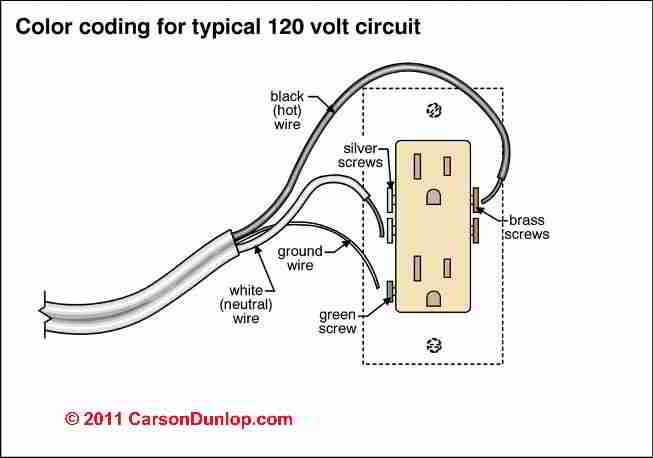 The illustration above shows the typical wiring of an electrical outlet or "receptacle", courtesy of Carson Dunlop Associates.
You can see the incoming ground wire aimed towards its connection point - the green screw on the electrical receptacle. But additional grounding connections are often required as well - as we will detail here.
Watch out: Electrical components in a building can easily cause an electrical shock, burn, or even death.
Even when a hot line switch is off, one terminal on the switch is still connected to the power source.
Before doing any work on the switch, the power source must be turned off by setting a circuit breaker to OFF or removing a fuse.
See SAFETY for ELECTRICAL INSPECTORS
and ELECTRICAL WIRING BOOKS & GUIDES
Connect the Ground Wires to the Receptacle
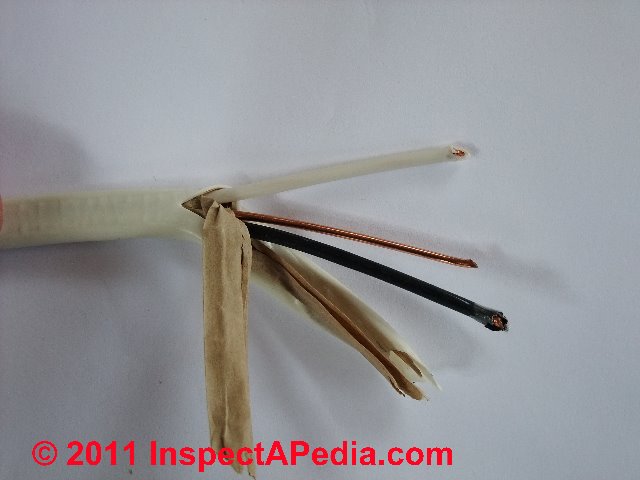
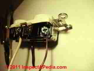
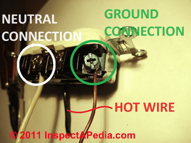
The bare ground wire - this wire, visible in our photo as the un-insulated copper wire seen between the white (top) and black (bottom) wires, connects to the green ground screw usually found on the bottom of the electrical receptacle (photo at left).
What if there is no ground wire in the circuit?
If you are connecting an electrical receptacle to an older circuit that just provides hot and neutral wires, that is, no ground, and assuming you're not going to re-wire the circuit to provide a proper ground, there is no ground wire to hook-up.
In this case you must use a type of electrical receptacle that does not include the third opening for the grounding prong on the wall plug.
Details are at 2-WIRE RECEPTACLE CONNECTIONS - no ground
Proper grounding connections for an electrical receptacle
The electrical receptacle must be properly connected to the building grounding system - not shown in our sketch below (again courtesy of Carson Dunlop Associates).
That connection is made from the ground screw on the receptacle to the grounding conductor (usually bare copper) in the wire leading back to the electrical panel where in that location it is connected to a grounding bus and from that bus to the building grounding system, one or more earth-driven electrodes or their equivalent.
The incoming ground wire is connected to the ground terminal on the electrical receptacle (usually a green screw such as shown in our photo at left).
If the junction box is metal (not plastic) the ground wire is also connected to the metal junction box itself, usually by a special green screw that connects to a tapped threaded hole on the junction box back side, or by a grounding clip that secures the ground wire to the edge of the metal box.
If there is more than one feeder wire entering the electrical junction box then all of the grounds are connected together as well as being connected to the ground screw on the receptacle itself.
If the junction box is plastic, you're done.
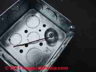
If the junction box is metal (photo above right) then a ground wire is also connected to the metal box using an approved grounding screw or clamp device to tie the wire end to the box.
Most metal electrical boxes have a threaded hole intended for use as a connection point for the ground wire connecting screw, as illustrated in our photograph (left).
In sum, all of the grounds are tied together in the box: the incoming ground, outgoing ground, and ground wires to each of the electrical receptacles and if it's metal, to the junction box itself.
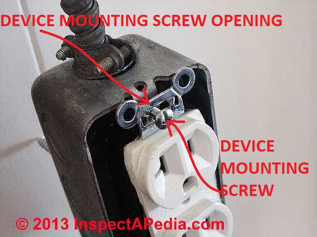
Watch out: Don't rely on the connection between the electrical outlet's steel mounting strap and the steel screw openings of the junction box to provide the ground connection. That's not a legal ground and it's unreliable
Use the a ground wire and ground screw on the receptacle itself to be sure that this important safety feature is correctly installed.
See ELECTRICAL GROUND SYSTEM INSPECTION
and Definition of Electrical Ground Terms.
It's easy for the receptacle mounting screws to be deliberately left loose or to work loose - making that ground connection unreliable. Use a ground wire, as the connection through the receptacle mount screws is simply not reliable.
Watch out: mis-wired electrical receptacles are dangerous. This article series describes how to choose, locate, and wire an electrical receptacle in a home.
...
Reader Comments, Questions & Answers About The Article Above
Below you will find questions and answers previously posted on this page at its page bottom reader comment box.
Reader Q&A - also see RECOMMENDED ARTICLES & FAQs
On 2020-06-25 - by (mod) - what's that odd jumper wire on the receptacle?
Was the copper tab between the two screws removed?
On 2020-06-25 by Marc
So, what I appear to have is.
Two black lines connected
Three neutral lines connected.
One black line connected to a red line to feed the next room while bypassing the switch on this plug.
I'm still wondering why there would be a small section of black wire running from one black plug-in port to the opposite black screw. It was attached with a second black line that was coming from outside the box.
Two wires in a screw port seemed odd
A wire across a single plug was odd. It looks like they reconnected a plug that had been split to run half hot? The plug is replaced at this point and in a pile with 50 others, so I can't be sure.
Everything is wired as I found it minus that black cross wire everything works as expected, with no breakers tripping and nothing getting hot.
On 2020-06-24 by (mod) -
If the receptacle of Switched typically you will find that the top or bottom receptacle opening is the switched one rather than both of them and they break off tab on that otherwise makes the two terminals on the hot or neutral side common is removed so that they can be wired individually.
I don't completely understand your description but it's possible that someone previously broken off at a band was trying to wire across to effectively replace the broken part I sneaking in an extra connection. Or someone is simply trying to include more black or hot wires does a receptacle provided for and didn't have room in the box for a Twist on connector splice.
Sounds like what you need to do is simply sort out where that other wire is going. You should by now know how to test to find which wires in the Box are line in or hot.
On 2020-06-24 by Marc
Sorry about the signal to noise. Think I have things sorted and will update after I cook dinner for the kids
On 2020-06-24 by Anonymous
Thanks for your comments and insight. The red wire feeds a plug in the bedroom directly above this room. I am very handy generally (cars appliances, etc) and I have been working my way though the house swapping new plugs and switches like for like to change colors. Yes, I am turning off breakers and testing outlets with a volt meter before work.
This outlet seemed strange (after the first 40, which were straightforward) since it had a black line coming out of the push-in port and attached to the opposite black screw port - together with another inbound black line from outside the box. It was almost like someone was trying to bridge the ports. Would that configuration be used if a single plug were switched?
Other than that, this has been a straightforward, though tedious exercise. It has also helped me properly label the breaker panel.
On 2020-06-24 - by (mod) -
Marc
With the emphatic warning that I cannot see all of the wiring nor assert that it's correct in your photo, I THINK that what we have is
Hot In (Line voltage in)
Neutral In
Ground In
Hot Out
Neutral Out
Ground Out
Another white, (usually) netural wire
going to the receptacle - that's what we see in a typical "daisy-chained" receptacle installation; the "out" wires are feeding power to the next receptacle "downstream"
And there is a red-black wire connection, presumably a hot circuit or wire powered out of this box - could be going to lighting or to a switch.
All of the ground wires in and out and to the ground terminals on the receptacle get bonded together; if the box were metal (yours is yellow plastic) it too would be connected to the ground.
An electrician would test every wire to confirm line voltage or "hot", neutral, and ground. And she would perhaps trace that red-to-black circuit to see wht it's powering.
Watch out: I'm obligated to warn that if you are not familiar with proper, safe electrical wiring & testing, you could be shocked or killed.
On 2020-06-24 by Marc
I just opened an outlet that has an extra 4" ground wire across the two plugs. In addition to that, there are two hot and two ground lines plus the third ground wire attached to the green screw.
There are three lines coming into this box.
1 w linked to plug
R linked to B of line #2
B. Linked to plug
Copper attached to copper on #3
Line #2
W linked to plug
R linked to black from #1 (wire nut)
No copper.
Line #3
W linked to plug
B liked to plug
Copper attached to plug
Do I ignore this extra wire in the new plug? I attached all three white wires to the plug and the two incoming black lines.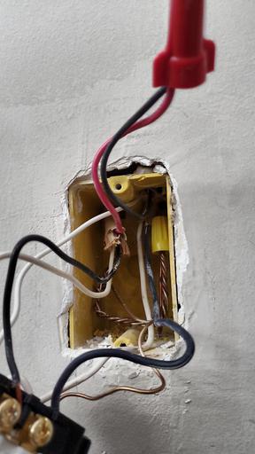
On 2020-05-30 16:04:09.067450 - by (mod) -
Lloyd
Well put, thank you.
On 2020-05-30 by Lloyd
Today with GFCI'S, to my knowledge the only acceptable method of bringing a non grounded circuit up to code without running a ground wire is with the use of a ungrounded GFCI specifically with the label "NO EQUIPMENT GROUND". This will protect the user but not the equipment.
On 2017-08-16 - by (mod) - converting an old 2 prong outlet to a new 3 prong (grounded) outlet
Bottom line: Yes you can do what you describe. But there may be easier places to connect the new grounding conductor that I'll describe.
Current U.S. National Electrical Code 250.130(C)(1) and 250.130(C)(4) permit you to run a new grounding conductor wire OR to connect to an existing circuit grounding conductor.
A non-grounding type receptacle can be replaced with a grounding type receptacle if an equipment grounding conductor is installed and connected to any accessible point on the grounding electrode system.
At ELECTRICAL CONNECTION for 2-WIRE RECEPTACLE CIRCUIT
I will repeat your question and give a more-detailed reply.
On 2017-08-08 by Dave
When converting an old 2 prong outlet to a new 3 prong (grounded) outlet - is it legal to run a new single ground wire from the new outlet back to the breaker box ground bar?
I.E. not replacing the existing BX wire.
With that same thought - if there are multiple new 3 prong outlets - do they all need run all the way back to the breaker box ground bar?
Or can the multiple outlets be branched off a main feeder wire back to the breaker box ground bar?
On 2017-05-12 - by (mod) - Do i have to get outlets without the green ground screw?
Excellent question, Jay.
Just this afternoon I replaced an old two prong, ungrounded electrical receptacle in the very same circumstance that I think you are describing.
They replace that receptacle that I purchased included a grounding connection - that is it except a 3 prong plug on a line cord.
When I opened the electrical box and removed the old ungrounded receptacle I found that there was a copper ground wire on the wiring that was connected yes to the metal electrical box.
I made sure that that ground wire was connected to both the green ground screw on the receptacle and to the metal box. That way there is a proper ground conductor for the new electrical receptacle, and the metal box also remains safely grounded.
If there had been no ground wire present, I would have installed a two prong older style receptacle that did not include a ground nectar for the wall plug
On 2017-05-12 by Jay
I have a old house and the grounds are connected to the box. Do i have to get outlets without the green ground screw? OR do i change the ground from the metal box to the outlet with the green screw?
On 2015-03-03 - by (mod) -
PS
If the switch has a ground screw it should be connected. Someone was perhaps joust in a hurry.
On 2015-03-03 by PSnape
I am replacing a single pole on/off switch with a dimmer in a two switch receptacle. Neither switch has the ground wire attached, instead the two ground wires are screwed together and just pushed into the back of the receptacle. When installing the dimmer should I attach the grounds to the switches or just leave them as is?
When I opened up several other switch receptacles in the house none of them had the ground connected. I don't know why the switches are not connected to the grounding wire.
On 2015-03-03 - by (mod) -
Safty
Because you'd be sending live current on the grounding conductor whenever something is plugged into the electrical receptacle; that wire is not only not intended to carry regular in-use current, but as the grounding system includes armored cable, water pipes, etc. someone could get zapped or fried.
On 2015-02-28 by safty ground
if the safty ground and negitive wire both go to the same grounding boss in the main why cant the safty be wired at the outlet to the neg. wire going to the main ?
Reader Question: how is an electrical outlet wired to the electrical panel?
how do wire the outlet plug to the electrical panel - Anon
Reply:
Anon, the electrical circuit that powers an "outlet plug" or receptacle is connected, usually through building walls, ceilings, or floors, from the first receptacle in the particular series back to a fuse or circuit breaker connection in the electrical panel.
The fuse or circuit breaker, by its connecting mount in the electrical panel, receives electrical power from the income electrical service.
Ultimately in the electrical box where the electrical receptacle ("wall plug" or "wall outlet" in common speech) is mounted,
- The incoming black or hot wire in the electrical box is connected to the bronze or brass colored screw on the receptacle; the other end of the hot wire is connected to the circuit breaker or fuse connector screw in the electrical panel.
- The incoming white or neutral wire in the electrical box is connected to the white or silver colored screw on the receptacle and the other end of the neutral wire connects to the neutral bus in the electrical panel.
- The incoming ground wire or grounding conductor in the electrical box connects to the green ground screw on the receptacle and also, by extension or pigtailing, to the junction box if the electrical box is metal not plastic.
In the electrical panel the other end of the grounding conductor connects to a ground bus bar that in turn is connected to earth, usually by grounding electrodes at the building exterior or in some jurisdictions to a buried metal water pipe.
Reader Question: what do I do with the screws to which no wire is connected on a conventional "plug" (wall receptacle)?
At the end of a circuit, I'm only using 2 of the 4 screws on a conventional plug. What should I do with the 2 unused screws? Should they be screwed all the way in? Or left partially unscrewed? Or does it matter? - Chris Rasko 7/8/12
Reply:
Chris:
regarding the un-used screw terminals on an electrical receptacle, you should simply screw them all the way in and leave them alone.
Don't completely-remove the screws - it's not necessary, they are deliberately hard to remove completely, and they could be needed in some future wiring change.
Question: When wiring an electrical receptacle, what do I do with the red wire? Can I ground it?
I have a 3 wire (Black, White, Red and ground) feeding a outlet and I want to add another receptacle to run further down the line. The line out is 14/2. What do I do with the Hot Red wire? Can i attach it to the ground. - Rick
Reply: NO!!
Rick:
NEVER connect a hot (red or black) wire to ground (nor to the white neutral wire) - doing so would form a dead short, should trip a breaker, or if not, could cause a fire or could cause a dangerous shock.
If there is a hot wire that is not used in a junction box, SOP would be to cap it off with a twist-on connector.
It sounds as if you'd be best served by hiring a licensed electrician.
Reader follow-up:
After capping off the red wire, can I extend the line to the next plug by following the diagram above and adding the black and white wires to the respective second screw connections?
You see, the wiring has already been installed by the builders and they left the boxes without receptacles so all I have to do is connect them to the. I don't know why the extra red wire is there. It was done over a year ago. I want to finish the connections. It runs 14/3 and then 14/2. That's why I have the extra red.
Reply: how three-wire circuits or multiwire branch circuits with a common neutral (and ground) are used and wired
Rick often electricians run a 3-wire system into a building area using two hot wires and a shared neutral, to permit providing two circuits in an area while having to pull just one wire to the area. But to sort out how your wires were connected and are being used requires some expertise, visual inspection, and testing using a VOM.
Take a look at multi-wire branch circuit wiring information and hook-up details
...
Continue reading at ELECTRICAL RECEPTACLE HEIGHT & CLEARANCES or select a topic from the closely-related articles below, or see the complete ARTICLE INDEX.
Or see
2-WIRE RECEPTACLE CONNECTIONS for proper wiring details - no ground available
ELECTRICAL RECEPTACLE CONNECTION DETAILS - where to connect black, white, red, green, ground wires.
GROUND SYSTEM INSPECTION - home
Suggested citation for this web page
GROUND WIRE CONNECTIONS at InspectApedia.com - online encyclopedia of building & environmental inspection, testing, diagnosis, repair, & problem prevention advice.
Or see this
INDEX to RELATED ARTICLES: ARTICLE INDEX to ELECTRICAL INSPECTION & TESTING
Or use the SEARCH BOX found below to Ask a Question or Search InspectApedia
Ask a Question or Search InspectApedia
Try the search box just below, or if you prefer, post a question or comment in the Comments box below and we will respond promptly.
Search the InspectApedia website
Note: appearance of your Comment below may be delayed: if your comment contains an image, photograph, web link, or text that looks to the software as if it might be a web link, your posting will appear after it has been approved by a moderator. Apologies for the delay.
Only one image can be added per comment but you can post as many comments, and therefore images, as you like.
You will not receive a notification when a response to your question has been posted.
Please bookmark this page to make it easy for you to check back for our response.
IF above you see "Comment Form is loading comments..." then COMMENT BOX - countable.ca / bawkbox.com IS NOT WORKING.
In any case you are welcome to send an email directly to us at InspectApedia.com at editor@inspectApedia.com
We'll reply to you directly. Please help us help you by noting, in your email, the URL of the InspectApedia page where you wanted to comment.
Citations & References
In addition to any citations in the article above, a full list is available on request.
- Timothy Hemm has provided photographs of various electrical defects used at the InspectAPedia TM Website. Mr. Hemm is a professional electrical inspector in Yucala, CA.
- Mark Cramer Inspection Services Mark Cramer, Tampa Florida, Mr. Cramer is a past president of ASHI, the American Society of Home Inspectors and is a Florida home inspector and home inspection educator. Mr. Cramer serves on the ASHI Home Inspection Standards. Contact Mark Cramer at: 727-595-4211 mark@BestTampaInspector.com
- John Cranor [Website: /www.house-whisperer.com ] is an ASHI member and a home inspector (The House Whisperer) is located in Glen Allen, VA 23060. He is also a contributor to InspectApedia.com in several technical areas such as plumbing and appliances (dryer vents). Contact Mr. Cranor at 804-873-8534 or by Email: johncranor@verizon.net
- [3] NFPA - the National Fire Protection Association can be found online at www.nfpa.org
- [4] The NEC National Electrical Code (ISBN 978-0877657903) - NFPA might provide Online Access but you'll need to sign in as a professional or as a visitor)
- US NEC Free Access: See up.codes at this link: https://up.codes/code/nfpa-70-national-electrical-code-2020
- [5] Special thanks to our reader Steve who pointed out prior errors in our illustrations.
- [6] Simpson Strong-Tie, "Code Compliant Repair and Protection Guide for the Installation of Utilities in Wood Frame Construction", web search 5/21/12, original source strongtie.com/ftp/fliers/F-REPRPROTECT09.pdf, [copy on file as /Structures/Framing/Simpson_Framing_Protectors.pdf ]. "The information in this guide is a summary of requirements from the 2003, 2006 and 2009 International Residential Code (IRC), International Building Code (IBC), International Plumbing Code (IPC), International Mechanical Code (IMC), 2006 Uniform Plumbing Code (UPC) and the 2005 National Electrical Code."
- "Electrical System Inspection Basics," Richard C. Wolcott, ASHI 8th Annual Education Conference, Boston 1985.
- "Simplified Electrical Wiring," Sears, Roebuck and Co., 15705 (F5428) Rev. 4-77 1977 [Lots of sketches of older-type service panels.]
- "How to plan and install electric wiring for homes, farms, garages, shops," Montgomery Ward Co., 83-850.
- "Simplified Electrical Wiring," Sears, Roebuck and Co., 15705 (F5428) Rev. 4-77 1977 [Lots of sketches of older-type service panels.]
- "Home Wiring Inspection," Roswell W. Ard, Rodale's New Shelter, July/August, 1985 p. 35-40.
- "Evaluating Wiring in Older Minnesota Homes," Agricultural Extension Service, University of Minnesota, St. Paul, Minnesota 55108.
- "Electrical Systems," A Training Manual for Home Inspectors, Alfred L. Alk, American Society of Home Inspectors (ASHI), 1987, available from ASHI. [DF NOTE: I do NOT recommend this obsolete publication, though it was cited in the original Journal article as it contains unsafe inaccuracies]
- "Basic Housing Inspection," US DHEW, S352.75 U48, p.144, out of print, but is available in most state libraries.
- In addition to citations & references found in this article, see the research citations given at the end of the related articles found at our suggested
CONTINUE READING or RECOMMENDED ARTICLES.
- Carson, Dunlop & Associates Ltd., 120 Carlton Street Suite 407, Toronto ON M5A 4K2. Tel: (416) 964-9415 1-800-268-7070 Email: info@carsondunlop.com. Alan Carson is a past president of ASHI, the American Society of Home Inspectors.
Thanks to Alan Carson and Bob Dunlop, for permission for InspectAPedia to use text excerpts from The HOME REFERENCE BOOK - the Encyclopedia of Homes and to use illustrations from The ILLUSTRATED HOME .
Carson Dunlop Associates provides extensive home inspection education and report writing material. In gratitude we provide links to tsome Carson Dunlop Associates products and services.


