 Electrical Receptacle Circuit Conductors
How many wires are needed to connect an electrical plug outlet or wall receptacle / plug?
- POST a QUESTION or COMMENT about how to install and wire electrical outlets or receptacles in buildings.
Number & Types of Wire needed to wire up an electrical receptacle:
This article explains that the number of conductors needed to hook up an electrical receptacle (or "wall outlet") ranges from a minimum of two in older homes with ungrounded knob and tube circuits to three or more when wiring a split-receptacle circuit or when wiring receptacles on a shared neutral or multiwire branch circuit. Here we sort out what you'll need.
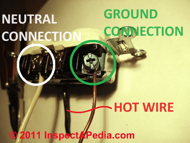
In this article series we illustrate basic connections seen in the field for the black, white neutral or grounded conductor), and ground wire when hooking up an electrical receptacle (wall plug or "outlet").
We describe how to wire an electrical receptacle by making the right connections between individual electrical wires and the proper screw or clamp connectors on the electrical receptacle device itself.
We also describe connecting the ground wire between the circuit grounding conductor, receptacle ground screw, and the electrical box (if metal boxes are used).
Watch out: mis-wired electrical receptacles are dangerous. Electrical wiring should be performed by a licensed, trained electrician and should comply with the National Electrical Code and local regulations.
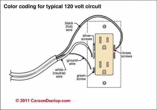
Page top sketch and others in this article: courtesy Carson Dunlop Associates, a Toronto home inspection and education company cited in page bottom references as well.,
This article series describes how to choose, locate, and wire an electrical receptacle in a home. Page top sketch provided courtesy of Carson Dunlop Associates, a Toronto home inspection & education expert.
InspectAPedia tolerates no conflicts of interest. We have no relationship with advertisers, products, or services discussed at this website.
- Daniel Friedman, Publisher/Editor/Author - See WHO ARE WE?
How Many Conductors Should be in the Receptacle Circuit? 2-Wire? 3-Wire? 2-Wire with Ground?
[Click to enlarge any image]
The illustration at the top of this page shows the typical wiring of an electrical outlet or "receptacle", courtesy of Carson Dunlop Associates. Just above we see three wires or conductors connected to an electrical receptacle: the minimum you'll need for connecting an electrical receptacle (or outlet or wall plug) where a ground is present (as it should be).
If you need help sorting out how black, white, red, green and bare wires are normally used,
see ELECTRICAL WIRING COLOR CODES.
Watch out: Electrical components in a building can easily cause an electrical shock, burn, or even death.
Even when a hot line switch is off, one terminal on the switch is still connected to the power source. Before doing any work on the switch, the power source must be turned off by setting a circuit breaker to OFF or removing a fuse.
Two wire14/2 and 12/2 Wires for 15-A or 20-A circuits
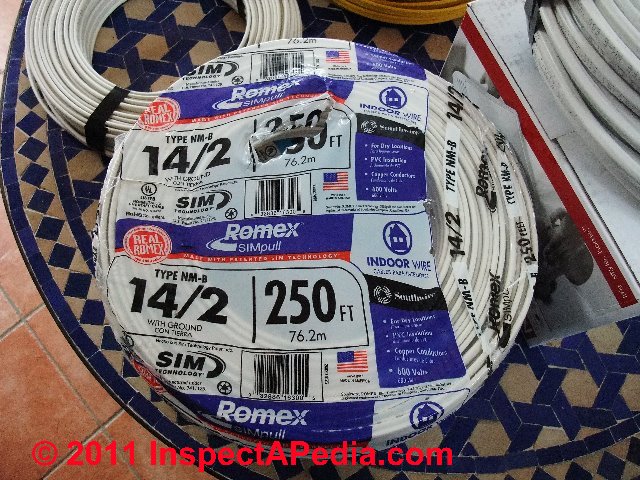
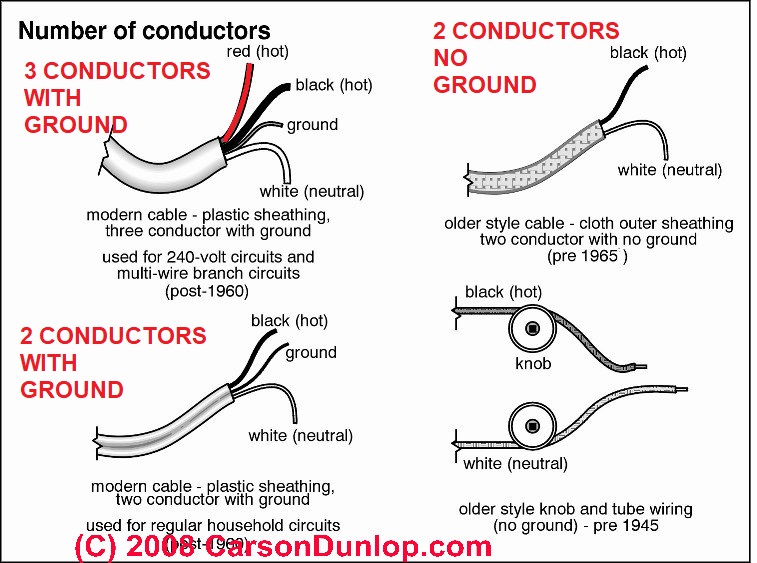
The electrical wire must have the proper number of conductors. In modern electrical circuits used to wire receptacles (electrical outlets).
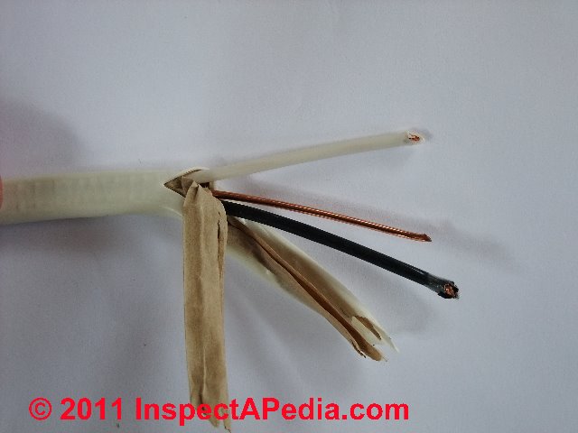
Typically an electrical receptacle is wired with two insulated wires and a bare ground wire, all three of which are encased in a plastic (NMC) or metal (BX) jacket.
You'll see this wire labeled as 14/2 Type NM B with ground (photo at left) or 14/2 Type NM C with ground.
These wires are color coded black, white, and bare (photo below right). Sketch at left showing the number of conductors in types of electrical wire is provided by of Carson Dunlop Associates.
Watch out: If your electrical circuit has only black and white wires, that is, no grounding conductor, then you are wiring a 2-wire electrical circuit that has no ground:
see 2-WIRE RECEPTACLE CONNECTIONS for proper wiring details.
14/3 and 12/3 Three-wire Shared Neutral Electrical Circuits for Receptacles
Some electricians run a three-wire, shared neutral circuit ( to permit two independent receptacle circuits in an area while pulling one less wire through the building. You'll see the labeling on such wires as 14/3 or 12/3.
A 14/3 or 12/3 wire will actually provide four physical wires: one neutral wire, two hot wires (black and red), and a ground wire. A common use of shared neutral circuits is the wiring of quad-receptacle hookups or duplex receptacle hookups in a kitchen where we want two separate 20-A circuits and thus might use 12/3 wire.
Watch out: AFCI and GFCI devices may not work properly when the neutral wire is shared. Since the kitchen circuit must be GFCI or AFCI protected, we can no longer recommend using shared neutral circuits in this location even if it is permitted.
Watch out: for a shared neutral circuit to function safely in the electrical panel the two hot wires are connected to a double pole common internal trip circuit breaker.
Details about how shared-neutral multiwire branch circuits are wired can be found
...
Reader Comments, Questions & Answers About The Article Above
Below you will find questions and answers previously posted on this page at its page bottom reader comment box.
Reader Q&A - also see RECOMMENDED ARTICLES & FAQs
Question: can't get an electrical switch to work on a combined receptacle-switch device
I am replacing an outlet that has the top half on a switch and the bottom half always on. The old outlet had stab wire connections for a black, white and RED wire in the top section.
I have tried to install the new outlet, using the screws as recommended, rather than the stab connections, and cannot make the top half work on the switch.
(I tried with the tabs in place, one tab removed and both tabs removed. Also tried the red & black on the same screw, red on the screw and black in the stab hole and the reverse.) How to I make the switch work? (July 30, 2014) Anne said:
Reply:
Anne I don't have a full picture of what you're doing but
first: be careful not to electrocute yourself or start a fire - a standard caveat I'd make to anyone not a trained electrician
Now, in general,
1. to power the upper and lower halves of a receptacle separately we have to break the line-in or black wire or power tab. You can break apart the tab on the white wire neutral side but those connections are going to be made common by a splice in the electrical box anyway.
2. The line-in power wire into the receptacle box is split into two feed wires. One goes to the lower "always on" half of the receptacle line in screw while the other connects to a wire leading to the receptacle switch. The return wire from that switch then connects to the line-in or black wire or gold-colored screw on the receptacle.
...
Continue reading at ELECTRICAL RECEPTACLE CONNECTION DETAILS or select a topic from the closely-related articles below, or see the complete ARTICLE INDEX.
Or see these
Recommended Articles
- ELECTRICAL OUTLET, HOW TO ADD & WIRE - home
- ELECTRICAL OUTLET ADAPTER SHORT CIRCUIT
- ELECTRICAL RECEPTACLE ARC PITTING
- ELECTRICAL RECEPTACLE CONNECTION DETAILS
- 2-WIRE RECEPTACLE CONNECTIONS
- WHICH SCREWS GET the BLACK, WHITE & GROUND WIRES ?
- WHICH WIRES GO to LINE or LOAD CONNECTIONS?
- HOW to CONNECT WIRES to a RECEPTACLE or SWITCH
- GROUND WIRE CONNECTION SUMMARY
- NUMBER of WIRES NEEDED: 2-WIRE, 3-WIRE, 2 or 3 WITH GROUND?
- ELECTRICAL DUPLEX RECEPTACLE WIRING
- ELECTRICAL OUTLET, HOW TO ADD in OLDER HOME
- ELECTRICAL RECEPTACLE WIRING SERIES vs PARALLEL
- ELECTRICAL SPLIT RECEPTACLE WIRING
- WIRES TOO SHORT TO CONNECT, REPAIR FOR
- GROUND WIRE CONNECTIONS
- MULTI-WIRE CIRCUITS
Suggested citation for this web page
NUMBER of WIRES NEEDED: 2-WIRE, 3-WIRE, 2 or 3 WITH GROUND? at InspectApedia.com - online encyclopedia of building & environmental inspection, testing, diagnosis, repair, & problem prevention advice.
Or see this
INDEX to RELATED ARTICLES: ARTICLE INDEX to ELECTRICAL INSPECTION & TESTING
Or use the SEARCH BOX found below to Ask a Question or Search InspectApedia
Ask a Question or Search InspectApedia
Try the search box just below, or if you prefer, post a question or comment in the Comments box below and we will respond promptly.
Search the InspectApedia website
Note: appearance of your Comment below may be delayed: if your comment contains an image, photograph, web link, or text that looks to the software as if it might be a web link, your posting will appear after it has been approved by a moderator. Apologies for the delay.
Only one image can be added per comment but you can post as many comments, and therefore images, as you like.
You will not receive a notification when a response to your question has been posted.
Please bookmark this page to make it easy for you to check back for our response.
IF above you see "Comment Form is loading comments..." then COMMENT BOX - countable.ca / bawkbox.com IS NOT WORKING.
In any case you are welcome to send an email directly to us at InspectApedia.com at editor@inspectApedia.com
We'll reply to you directly. Please help us help you by noting, in your email, the URL of the InspectApedia page where you wanted to comment.
Citations & References
In addition to any citations in the article above, a full list is available on request.
- Timothy Hemm has provided photographs of various electrical defects used at the InspectAPedia TM Website. Mr. Hemm is a professional electrical inspector in Yucala, CA.
- Mark Cramer Inspection Services Mark Cramer, Tampa Florida, Mr. Cramer is a past president of ASHI, the American Society of Home Inspectors and is a Florida home inspector and home inspection educator. Mr. Cramer serves on the ASHI Home Inspection Standards. Contact Mark Cramer at: 727-595-4211 mark@BestTampaInspector.com
- John Cranor [Website: /www.house-whisperer.com ] is an ASHI member and a home inspector (The House Whisperer) is located in Glen Allen, VA 23060. He is also a contributor to InspectApedia.com in several technical areas such as plumbing and appliances (dryer vents). Contact Mr. Cranor at 804-873-8534 or by Email: johncranor@verizon.net
- [3] NFPA - the National Fire Protection Association can be found online at www.nfpa.org
- [4] The NEC National Electrical Code (ISBN 978-0877657903) - NFPA might provide Online Access but you'll need to sign in as a professional or as a visitor)
- US NEC Free Access: See up.codes at this link: https://up.codes/code/nfpa-70-national-electrical-code-2020
- [5] Special thanks to our reader Steve who pointed out prior errors in our illustrations.
- [6] Simpson Strong-Tie, "Code Compliant Repair and Protection Guide for the Installation of Utilities in Wood Frame Construction", web search 5/21/12, original source strongtie.com/ftp/fliers/F-REPRPROTECT09.pdf, [copy on file as /Structures/Framing/Simpson_Framing_Protectors.pdf ]. "The information in this guide is a summary of requirements from the 2003, 2006 and 2009 International Residential Code (IRC), International Building Code (IBC), International Plumbing Code (IPC), International Mechanical Code (IMC), 2006 Uniform Plumbing Code (UPC) and the 2005 National Electrical Code."
- "Electrical System Inspection Basics," Richard C. Wolcott, ASHI 8th Annual Education Conference, Boston 1985.
- "Simplified Electrical Wiring," Sears, Roebuck and Co., 15705 (F5428) Rev. 4-77 1977 [Lots of sketches of older-type service panels.]
- "How to plan and install electric wiring for homes, farms, garages, shops," Montgomery Ward Co., 83-850.
- "Simplified Electrical Wiring," Sears, Roebuck and Co., 15705 (F5428) Rev. 4-77 1977 [Lots of sketches of older-type service panels.]
- "Home Wiring Inspection," Roswell W. Ard, Rodale's New Shelter, July/August, 1985 p. 35-40.
- "Evaluating Wiring in Older Minnesota Homes," Agricultural Extension Service, University of Minnesota, St. Paul, Minnesota 55108.
- "Electrical Systems," A Training Manual for Home Inspectors, Alfred L. Alk, American Society of Home Inspectors (ASHI), 1987, available from ASHI. [DF NOTE: I do NOT recommend this obsolete publication, though it was cited in the original Journal article as it contains unsafe inaccuracies]
- "Basic Housing Inspection," US DHEW, S352.75 U48, p.144, out of print, but is available in most state libraries.
- In addition to citations & references found in this article, see the research citations given at the end of the related articles found at our suggested
CONTINUE READING or RECOMMENDED ARTICLES.
- Carson, Dunlop & Associates Ltd., 120 Carlton Street Suite 407, Toronto ON M5A 4K2. Tel: (416) 964-9415 1-800-268-7070 Email: info@carsondunlop.com. Alan Carson is a past president of ASHI, the American Society of Home Inspectors.
Thanks to Alan Carson and Bob Dunlop, for permission for InspectAPedia to use text excerpts from The HOME REFERENCE BOOK - the Encyclopedia of Homes and to use illustrations from The ILLUSTRATED HOME .
Carson Dunlop Associates provides extensive home inspection education and report writing material. In gratitude we provide links to tsome Carson Dunlop Associates products and services.


