 Electrical Receptacle Arcing Damage
Arc pitting / burns on an older electrical outlet
- POST a QUESTION or COMMENT about how to install and wire electrical outlets or receptacles in buildings.
Arc pitting and burn damage to an electrical receptacle:
This article describes the loss of electrical power at a wall receptacle and its repair (by replacing the old device with a new one).
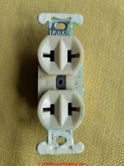
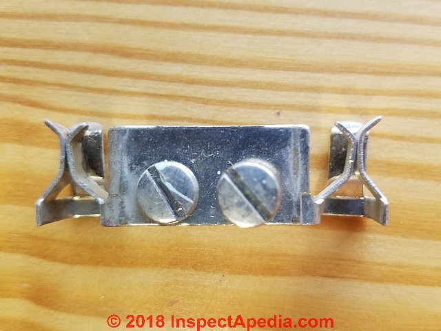
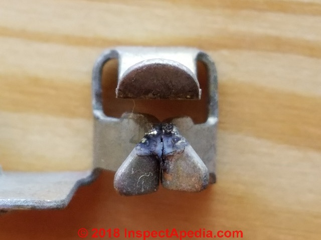
Page top photo: arc burns and welded, then broken contacts from the interior of an electrical receptalce ("outlet") of a Two Harbors Minnesota home repaired by the author.
We include photographs of conditions inside of this receptacle that failed, probably due to arc burning or pitting after nearly 60 years of service.
InspectAPedia tolerates no conflicts of interest. We have no relationship with advertisers, products, or services discussed at this website.
- Daniel Friedman, Publisher/Editor/Author - See WHO ARE WE?
Arcing, Pitting, Damaged Contacts in an Electrical Receptacle
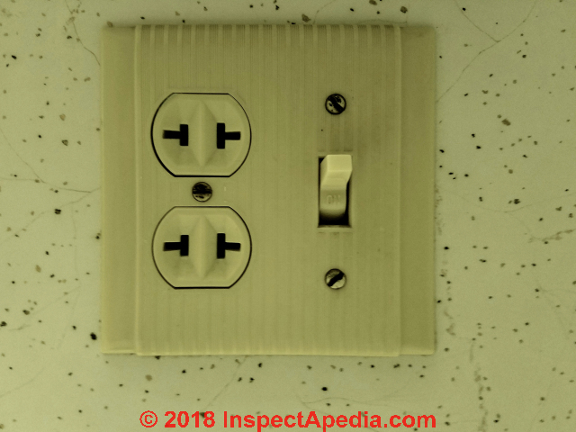 The electrical receptacle shown here and at page top was installed in the bathroom a home in Northern Minnesota when the home was built in 1962. The receptacle, a Leviton® product, was in just-about daily use to power small appliances including a hair dryer and occasionally a small electric heater.
In 2018 I [DF] was asked to repair the "electrical outlet" as it had stopped working. After dropping power to the circuit I removed the old receptacle, replaced it, and then disassembled the old device to examine the conditions inside.
These photographs and comments show what I observed.
Watch out: Electrical components in a building can easily cause an electrical shock, burn, or even death. Even when a hot line switch is off, one terminal on the switch is still connected to the power source.
Before doing any work on the switch, the power source must be turned off by setting a circuit breaker to OFF or removing a fuse.
Special thanks to Dr. Dr. Jess Aronstein for providing terminology for these observations. He commented that
It is possible that the arc pitting that you see resulted from removing the plug with the heater or hair dryer still on. AKA a "parting arc".
Below: the receptacle after it was removed from the wall box. From the face side there was no obvious damage but the occupants reported that plugs were "loose" in the receptacle for some time and that finally it "... just stopped working".
This receptacle was installed on a 20A copper-wired circuit.
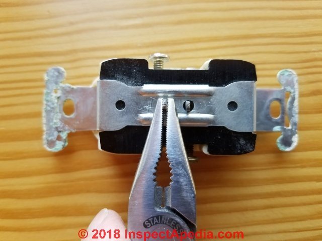
Below: bending two pins upwards permitted removal of the receptacle's mounting strap.
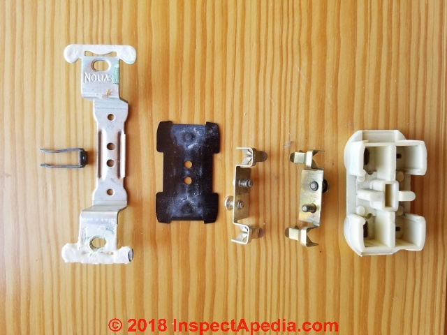
Below: the components of the device before taking a closer look.
Above, left to right: the securing pin, steel mounting strap, bakelite rear cover, the wiring and plug-spade connectors, and the plastic receptacle housing.
Also see ASBESTOS in PLASTICS
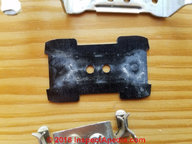
Below: there was plenty of white arc-flash deposit on the interior surface of the bakelite receptacle cover.
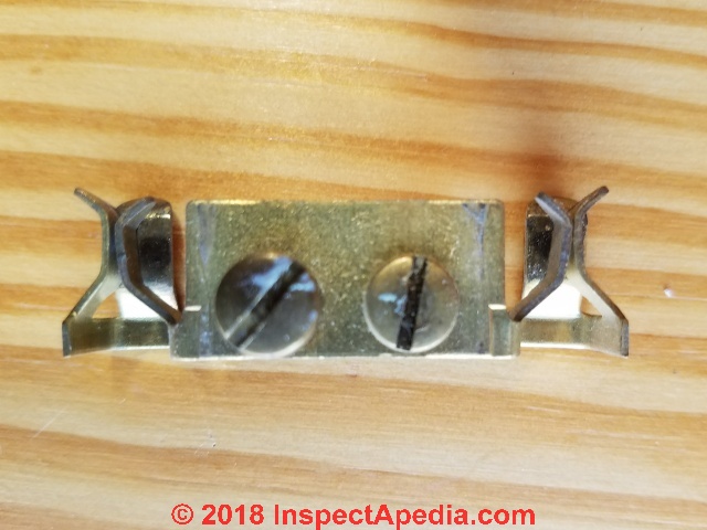
Below: the neutral connector screws and plug-spade connectors appeared to be un-damaged.
Below: the hot connectors showed some sign of (possible) overheating: the discoloration on the screw at left in the photo, and some arc pitting.
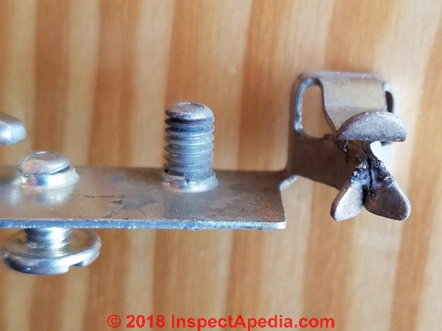
Below: taking a look at one of the receptacle's plug connectors I saw considerable arcing and discoloration on the shaft of the nearby wire-connecting screw.
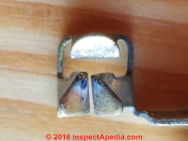
Below: taking a closer look at the two plug connectors of the hot side of this receptacle we see arc flash and in the second photo some melting of the connector.
This receptacle served the occupants of this home from 1962 to 2018, powering various devices and, though it ultimately failed, it "failed safe" in that it stopped working without causing an electrical fire or other damage. The original electrical wiring, box, and device all did their job even under somewhat demanding conditions.
OPINION: While there are still high-quality electrical devices sold in North America by Leviton and other companies, I'm not sure that the lower-cost receptacles presently sold in the U.S. market are made of similarly durable materials nor that they will share the same 56-year service life without a failure.
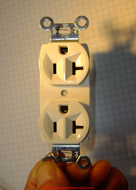
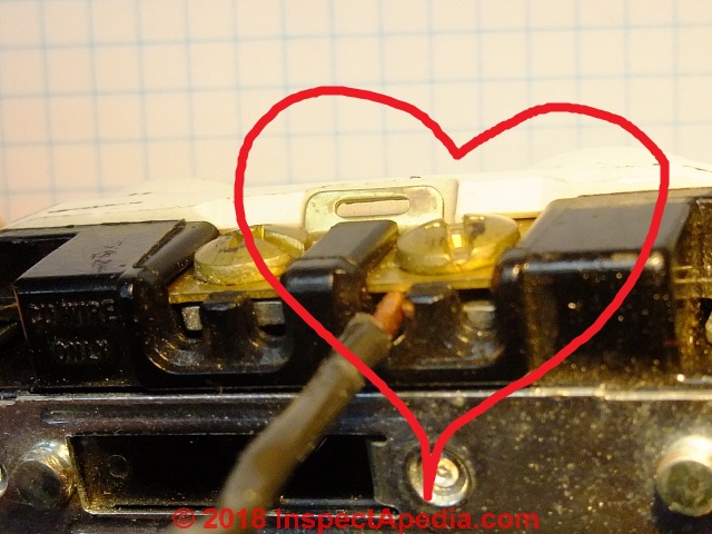
Below: here is the 20-A rated grounded electrical receptacle selected to replace the damaged device in this home.
This receptacle uses a screw-clamp type connector for which I have considerable affection.
...
Reader Comments, Questions & Answers About The Article Above
Below you will find questions and answers previously posted on this page at its page bottom reader comment box.
Reader Q&A - also see RECOMMENDED ARTICLES & FAQs
Question: can't get an electrical switch to work on a combined receptacle-switch device
I am replacing an outlet that has the top half on a switch and the bottom half always on. The old outlet had stab wire connections for a black, white and RED wire in the top section. I have tried to install the new outlet, using the screws as recommended, rather than the stab connections, and cannot make the top half work on the switch.
(I tried with the tabs in place, one tab removed and both tabs removed. Also tried the red & black on the same screw, red on the screw and black in the stab hole and the reverse.) How to I make the switch work? (July 30, 2014) Anne said:
Reply:
Anne I don't have a full picture of what you're doing but
first: be careful not to electrocute yourself or start a fire - a standard caveat I'd make to anyone not a trained electrician
Now, in general,
1. to power the upper and lower halves of a receptacle separately we have to break the line-in or black wire or power tab. You can break apart the tab on the white wire neutral side but those connections are going to be made common by a splice in the electrical box anyway.
2. The line-in power wire into the receptacle box is split into two feed wires. One goes to the lower "always on" half of the receptacle line in screw while the other connects to a wire leading to the receptacle switch. The return wire from that switch then connects to the line-in or black wire or gold-colored screw on the receptacle.
Question: Wiring a four-plate electric stove
(Oct 30, 2014) James said:
I am an apprentice in house wiring I wired a four plate stove like this: I installed 30A circuit breaker in the consumer unit and ran wires to the kitchen where I connected the wires coming from the breaker box to the line (input) an I connected the load to the stove I used 2.5mm.
I tested the it and is working but now my question is did I do it right? is the 2.5mm ok for the circuit? Is there a negative impact the wire size will have in future?
Reply:
James you don't identify your country nor voltage levels. Typically an electric stove is wired on a 220V-240V circuit, sometimes depending on stove design, some burners may use always or part time just one 120V leg. I'm not quite clear on what you did. Did the 4-plate electric stove come with wiring instructions and a wiring diagram?
Question: Tom Planer doesn't like photos of electrical wiring details
Tom Planer said:
I would be embarrassed to say I allowed the pictures in this article to be a part of this page.
You really need to take a quick look at NFPA Article 110.3 and 110.4 and do it quick.
Tom
Reply:
Tom, thank you for your comment.
Indeed I expect licensed electricians to know how to make proper electrical connections.
And to be familiar with the national electrical code. We do, however, often include photographs of as-is wiring as important illustrations of what's found in the real world - in the field. Showing what people actually do, right and wrong, can be useful.
While we regret that you might be embarrassed, explicit, technical comment would be more helpful than shame tossed over the electronic-wall.
Your comment to look at NFPA Article 110.3 probably intended to refer to the National Electrical Code NEC 110.3 which gives advice for the examination, installation, and use of [electrical] equipment and includes the expectation that such wiring details are inspected by the local electrical code compliance officer.
NEC 110.4 includes "The voltage rating of electrical equipment shall not be less than the nominal voltage of a circuit to which it is connected. "
Referring readers to a mere paragraph number that points to lengthy electrical code specification without any specifics is not helpful.
Thanks - Moderator.
...
Continue reading at ELECTRICAL OUTLET ADAPTER SHORT CIRCUIT or select a topic from the closely-related articles below, or see the complete ARTICLE INDEX.
Or see these
Recommended Articles
- ELECTRICAL CIRCUITS, SHORTS
- ELECTRICAL OUTLET, HOW TO ADD & WIRE - home
- ELECTRICAL OUTLET ADAPTER SHORT CIRCUIT
- ELECTRICAL RECEPTACLE ARC PITTING
- ELECTRICAL RECEPTACLE CONNECTION DETAILS
- 2-WIRE RECEPTACLE CONNECTIONS
- WHICH SCREWS GET the BLACK, WHITE & GROUND WIRES ?
- WHICH WIRES GO to LINE or LOAD CONNECTIONS?
- HOW to CONNECT WIRES to a RECEPTACLE or SWITCH
- GROUND WIRE CONNECTION SUMMARY
- NUMBER of WIRES NEEDED: 2-WIRE, 3-WIRE, 2 or 3 WITH GROUND?
- ELECTRICAL DUPLEX RECEPTACLE WIRING
- ELECTRICAL OUTLET, HOW TO ADD in OLDER HOME
- ELECTRICAL RECEPTACLE WIRING SERIES vs PARALLEL
- ELECTRICAL SPLIT RECEPTACLE WIRING
- WIRES TOO SHORT TO CONNECT, REPAIR FOR
- ELECTRICITY TURN ON AFTER BREAKER TRIP
- GROUND WIRE CONNECTIONS
- LIGHTNING DAMAGE to ELECTRICAL SYSTEM
Suggested citation for this web page
ELECTRICAL RECEPTACLE ARC PITTING at InspectApedia.com - online encyclopedia of building & environmental inspection, testing, diagnosis, repair, & problem prevention advice.
Or see this
INDEX to RELATED ARTICLES: ARTICLE INDEX to ELECTRICAL INSPECTION & TESTING
Or use the SEARCH BOX found below to Ask a Question or Search InspectApedia
Ask a Question or Search InspectApedia
Try the search box just below, or if you prefer, post a question or comment in the Comments box below and we will respond promptly.
Search the InspectApedia website
Note: appearance of your Comment below may be delayed: if your comment contains an image, photograph, web link, or text that looks to the software as if it might be a web link, your posting will appear after it has been approved by a moderator. Apologies for the delay.
Only one image can be added per comment but you can post as many comments, and therefore images, as you like.
You will not receive a notification when a response to your question has been posted.
Please bookmark this page to make it easy for you to check back for our response.
IF above you see "Comment Form is loading comments..." then COMMENT BOX - countable.ca / bawkbox.com IS NOT WORKING.
In any case you are welcome to send an email directly to us at InspectApedia.com at editor@inspectApedia.com
We'll reply to you directly. Please help us help you by noting, in your email, the URL of the InspectApedia page where you wanted to comment.
Citations & References
In addition to any citations in the article above, a full list is available on request.
- Dr. Jess Aronstein, protune@aol.com is a research consultant and an electrical engineer in Schenectady, NY. Dr. Aronstein provides forensic engineering services and independent laboratory testing for various agencies. Dr. Aronstein has published widely on and has designed and conducted tests on aluminum wiring failures, Federal Pacific Stab-Lok electrical equipment, and numerous electrical products and hazards.
Contact: J. Aronstein Consulting Engineer Bme, Msme, Ph.D., NYS. P.E. Lic. No. 39860, 909 Londonderry Ct., Schenectady, NY 12309 USA, Tel: (845) 462-6452 Email: AronsteinJesse@ieee.org
See ALUMINUM WIRING BIBLIOGRAPHY
and FPE HAZARD REPORT - 2017 [PDF] i independent research article by Jess Aronstein, supercedes older FPE hazard reports by this author. Information for Homeowners, Inspectors, and Electricians (Updated November 10, 2017), FEDERAL PIONEER PANEL SAFETY and FPE HAZARD ARTICLES, STUDIES, and BACK-WIRED ELECTRICAL DEVICES also CIRCUIT BREAKER FAILURE RATES and UBI FPE CIRCUIT BREAKER TEST RESULTS also ZINSCO FAILURE REPORTS for examples. - "Evaluating Wiring in Older Minnesota Homes," Agricultural Extension Service, University of Minnesota, St. Paul, Minnesota 55108.
- In addition to citations & references found in this article, see the research citations given at the end of the related articles found at our suggested
CONTINUE READING or RECOMMENDED ARTICLES.
- Carson, Dunlop & Associates Ltd., 120 Carlton Street Suite 407, Toronto ON M5A 4K2. Tel: (416) 964-9415 1-800-268-7070 Email: info@carsondunlop.com. Alan Carson is a past president of ASHI, the American Society of Home Inspectors.
Thanks to Alan Carson and Bob Dunlop, for permission for InspectAPedia to use text excerpts from The HOME REFERENCE BOOK - the Encyclopedia of Homes and to use illustrations from The ILLUSTRATED HOME .
Carson Dunlop Associates provides extensive home inspection education and report writing material. In gratitude we provide links to tsome Carson Dunlop Associates products and services.


