
 Wire Electrical Outlets in an Older Home
How to add & wire a grounded electrical receptacle in an older home
- POST a QUESTION or COMMENT about how to install and wire electrical outlets or receptacles in buildings.
How to install an electrical receptacle - or a series of them in an older home where routing wiring or finding a ground wire can be a challenge.
This article series explains electrical receptacle types (also referred to as wall sockets, outlets, or "plugs" by non-electricians), receptacle grounding, connecting wires to the right receptacle terminal screws, electrical wire size, electrical wire color codes, and special receptacles for un-grounded circuits.
InspectAPedia tolerates no conflicts of interest. We have no relationship with advertisers, products, or services discussed at this website.
- Daniel Friedman, Publisher/Editor/Author - See WHO ARE WE?
Add-On Electrical Outlet Wiring Instructions for Old Houses
 Our photo shows one of the steps in routing an electrical wire to add receptacles along the wall of a second floor bedroom of an older New York home in Poughkeepsie.
The procedure described here for adding a string of wall receptacles in this 1910 three story home can also be followed if all you need is to add a grounding conductor to permit use of grounded receptacles where an older two-wire without ground circuit is already installed - provided that the existing circuit is in good condition and properly-wired.
[Click to enlarge any image]
Watch out: if you are not trained in safe, proper electrical work you could be shocked or killed. See also
SAFETY for ELECTRICAL INSPECTORS - home
After being safe, the two essential challenges in adding one or more wall receptacles or "wall plugs" in an older home are
- Getting electrical power, including a grounding conductor, to the room where receptacles are needed
- Routing wires in the room to add receptacles while causing the least damage to the existing walls, ceilings, or floors
Step 1: Inspect the electrical panel
We want to know the service ampacity provided, the condition of the electrical panel, whether or not we can add a circuit in the panel if necessary, and where all of the breakers or fuses are located so that we an work safely on an existing circuit by first powering it off.
Step 2: Survey the building to find a suitable power source
We will either need to run an entirely new circuit from the electrical panel, or if there is a minimally-used existing receptacle circuit we might be permitted to extend that one to the room where we want to add outlets.
Step 3. Get power to the room where circuits are to be added
We looked for an under-used existing circuit that was as close as possible to the room where receptacles are to be added. For this home we found that one tiny office sporting two receptacles had its own circuit for those devices.
In the attic above we located that circuit in order to add an electrical box that would permit us to splice-in an extension that we could drop down to the room where circuits were to be added.
We cut the existing circuit at a convenient location in the attic floor, installed an electrical box that would remain accessible (rather than stymie future electrical workers and to comply with the electrical code), and then we could route a wire to a wall of the room where receptacles were to be added.
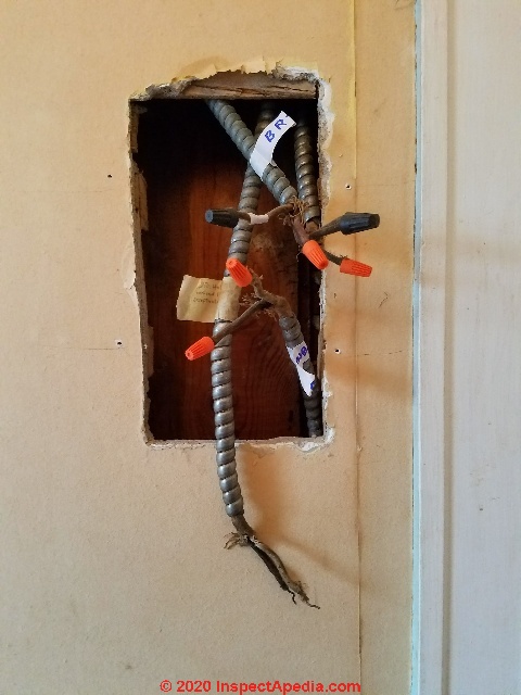
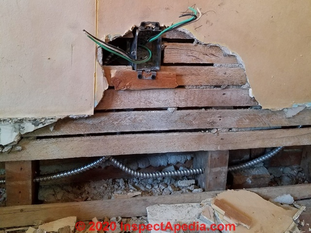
We found that there was already a junction box near the entry door to the room where we wanted to add receptacles. Opening up the wall in that location would make it a bit easier to snake our new power line down to the bottom of the floor.
If necessary we could add a larger junction box and make splices in the enlarged space.
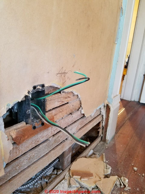
We dropped the new wire through the wall, in an interior partition (so as not to run into insulation or more obstructions), and snaked it down to the point in the room from which our string of new receptacles would begin. We began our circuit alongside the entry door to the room.
From this point we would extend the new circuit wire down to the floor to begin our chain of receptacles.
Watch out: if you have to remove or disassemble existing splices to install a larger junction box be sure that you label every wire and every connection before disconnecting them. That will save a lot of testing, arm-waving, shouting, and head scratching later.
Step 4. Prepare access to add circuit wiring around the room
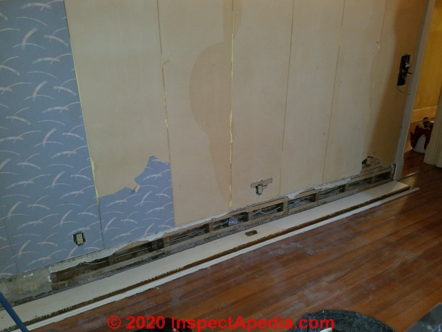
By carefully removing the baseboard trim along the floor of the room we had ready access to the wood-framed wall cavity around the room.
That gave a working space in which we could drill wall studs, route the wires near the floor in a space that would be covered when the baseboard trim was to be restored, and we could simply route the circuit up in the wall to an opening cut for each electrical box that would house a receptacle.
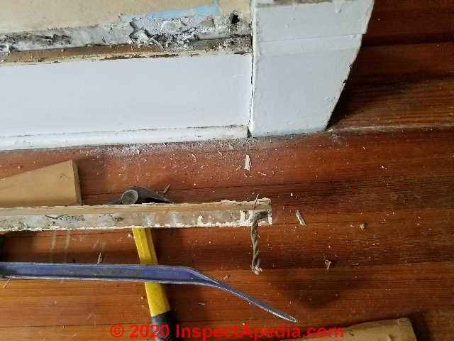
Working carefully with a couple of flat bars and my lightweight Japanese carpenter's hammer it was easy to remove the three pieces of trim that comprised the baseboard. Take are not to break or damage the trim if it's to be restored later - as is often the object in old or historic homes.
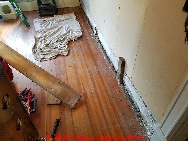
Watch out: for encountering old wires - they may be live. In this room we found old bell wire from a telephone removed long ago, and along the first run of baseboard we found an electrical box that had a blind cover suggesting that there used to be a receptacle wired here but the location was no longer in use.
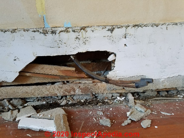
Watch out: if you cannot completely remove old electrical wires, don't bury or hide them in the wall, ceiling or floor. We capped off the wires and at the end of the job left them enclosed in an electrical box with a blind cover.
In some installations if we are sure that the circuit is "dead" but cannot remove the wire, we might tie the hot and neutral together using a twist-on connector. Our hope is that if in the future someone finds the other end of these wires and foolishly or in error connects them to a live circuit, the breaker or fuse will trip or blow immediately - a sound warning.
With the baseboard trim removed you can remove the bottom few inches of plaster and lath (or drywall in a newer home) to give access to the wall cavity. To minimize the wall repair at the end of the wiring job, don't remove sound wall materials higher above the floor than will be covered by the wall trim when you're restoring the wall.
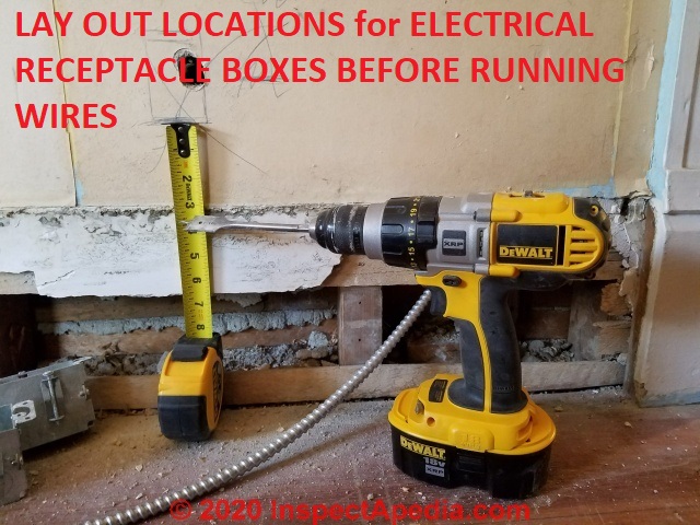
Step 5: Mark the new receptacle locations and make wall cuts to mount old work electrical boxes
Before beginning to run the new armored cable (BX) along the opening provided by removing the floor trim baseboard, prefer to mark the location of the new receptacles.
That data assures that we will provide proper wire lengths to reach from the floor level up to each new receptacle box.
Watch out: before beginning to cut out the wall opening for the receptacle box check that you're not about to drill or saw into a hidden water or gas pipe. Knowing where the other mechanicals run in the building walls, ceilings, floors, is important.
Our tape assured uniform box height around the room. If you care,
see ELECTRICAL OUTLET HEIGHT ABOVE FLOOR
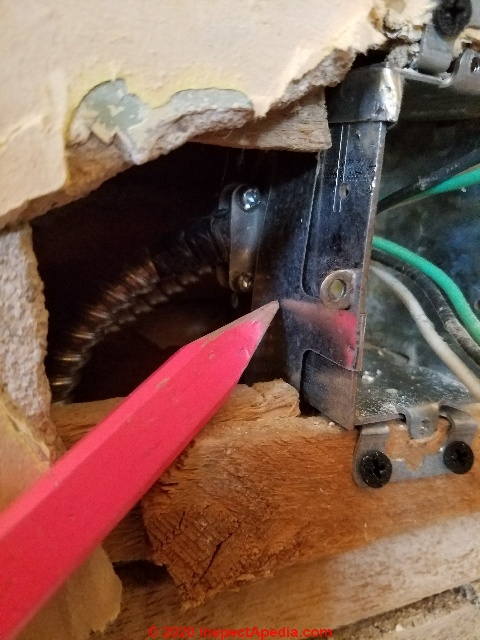
The wall opening has to be just big enough to pass the old work electrical box and its side ears or mounting devices.
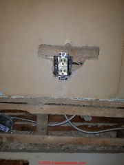
Then you can drill a pilot hole (shown above) and use a jigsaw with a carbide blade to cut the receptacle box opening marked on the wall. An ordinary toothed jigsaw blade will also work but the plaster will dull the blade to toothless rather quickly.
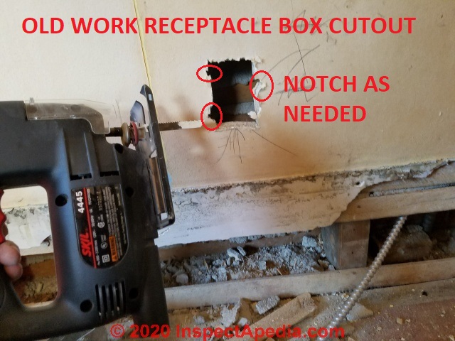
Notice that I kept the holes as small as possible to make box mounting easy and secure, but I notched out where screws or ears needed to pass by the plaster and lath.
We used old-work electrical boxes to make adding the boxes easier. Those are described in detail
at OLD WORK ELECTRICAL BOXES for RETROFIT
Before connecting the BX electrical cable to the old work box, test fit to see that you will be able to slip the box into the opening.
Note that depending on the type of strain relief used to connect the cable to the box you may need to enlarge the bottom of the cutout to fit the wired-box back into the wall.
Watch out: when enlarging the wall opening to install the old work box, keeping the openings as small as possible reduces the amount of wall plastering and repair work you'll need to do later so as to assure that no wall openings extend past the receptacle box cover plate.
Step 6: Run the electrical circuit wires along the floor, in the wall, to the box locations
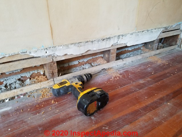
If you haven't already done-so, drill the wire routing holes through the center of each wall stud, a few inches above the floor.
 ...
... 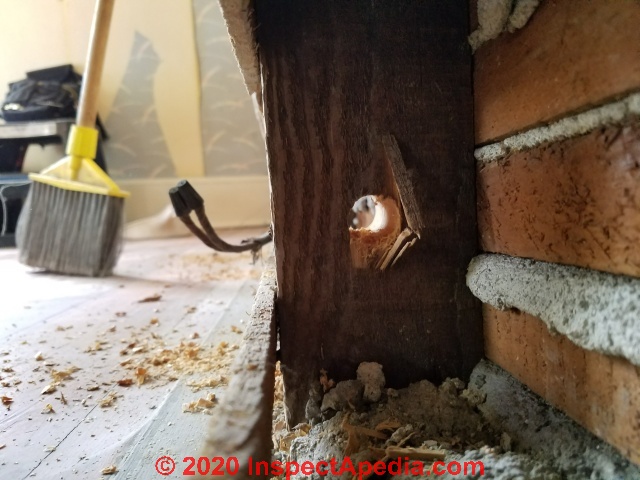
Watch out: if you cannot locate the wire passage in the center of the wall stud you'll need to use nail plates to protect the wire from damage that can occur when re-nailing the floor trim to the wall.
See NAIL STOPS to PROTECT WIRES
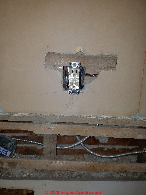
Below, in a photo taken after the electrical box has been installed, you can see our BX cable running along the floor level, through the studs, and up to the receptacle box. At the left side of the photo the BX is dropped down from the attic above, then begins its run along the floor where we removed the floor kick board trim.
Watch out: don't be surprised if some of the plaster in an old home is fragile and breaks apart while cutting openings for each electrical box. In particular, sawing wood lath in a location not immediately-adjacent to a wall stud increases the chance that you'll break away some plaster as the free-end of the wood lath will wiggle like a wild snake when attacked by a jig-saw.
Sawing more-slowly might have reduced this damage but in this case we rationalized by noting that in this renovation job we already knew there would be plaster repair necessary in this 1910 home.
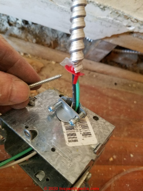
Step 7: Connect circuit wires to each electrical box and mount the boxes in the wall
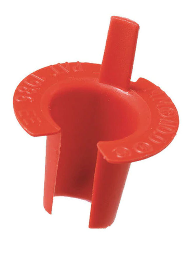
Watch out: Don't forget those (red) anti-short bushings: plastic BX inserts that prevent the wire insulation from being damaged or even shorted wires cut by the edge of the BX cable. Shown here is a Zoro anti-short bushing sold by electrical and building suppliers.
(Note the NMC type but supposedly dual-purpose strain relief on the electrical box? Not the best fit for round armored cable - Ed.)
 ...
... 
On another job my brother in law Matt, a theater electrician, over-tightened the strain reliefs on the electrical boxes in his apartment, cutting into and shorting every single wire at every box on his wiring job. Don't do that.
Morris Products, Arlington, Sigma, Zoro, Graybar, Raco and other manufacturers provide versions of these anti-short bushings so there's no excuse for leaving them out.
 ...
... 
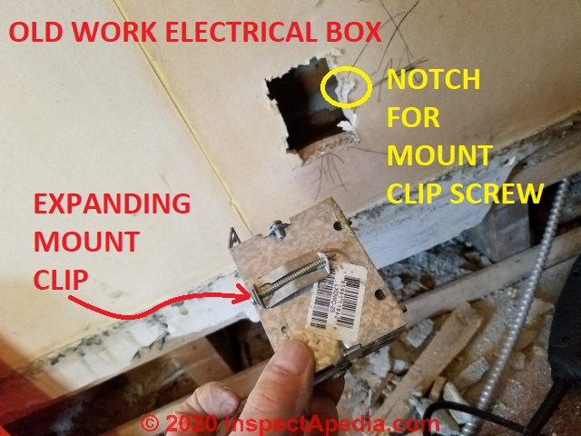
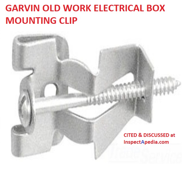
Above we illustrate two different type of old-work electrical box mounting systems: flat steel clips (also called "Madison Bars") that slip into the wall alongside the box and bend into the box to secure it (pull the box tight against the clips during bending),
or an expanding clip that opens behind the lath and secures the box to the wall by tightening the clap screw - shown below.
 ...
... 
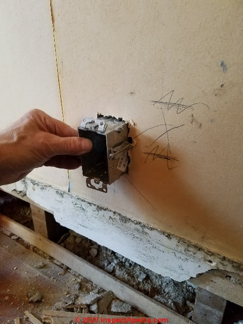
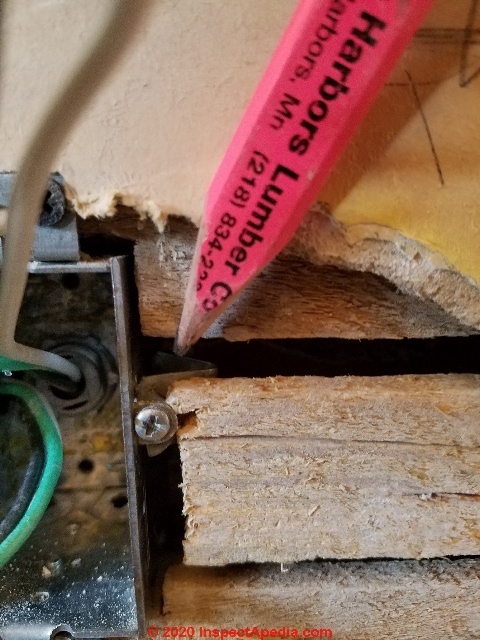
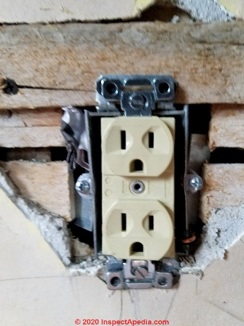
Below: this electrical box is secured in the wall using both types of connectors.
 On the left side of the box (above) the short bit of lath was not strong enough to work with the expanding screw-clip but the flat bend-in clip worked perfectly.
Watch out: every electrical box needs to be very secure in the wall opening before completing wiring of the receptacle.
A loose electrical receptacle is dangerous and can pull right out of the wall later when someone is trying to un-plug their appliance or some other device.
The box is secured against the wall surface by its mounting hardware and may be pulled tight in the wall by the ears of the electrical receptacle when that device is mounted to the electrical box later.
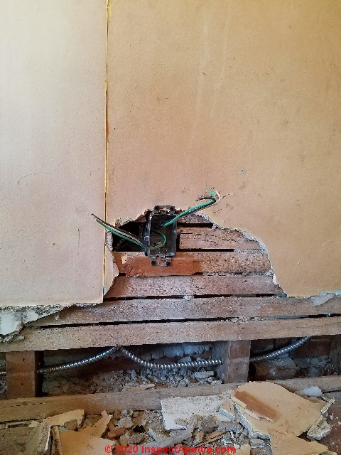
Above: the box is secured into the plaster-lath wall and we now have a grounded electrical circuit (Black-hot, white-neutral, green-ground).
Watch out: providing a "grounding conductor" at an extended or new electrical circuit is incomplete and unsafe unless you make absolutely sure that the grounding conductor itself is routed all the way back to a proper termination in the electrical panel.
Never rely on the BX sheathing itself as a ground path. Doing that is unreliable, and worse, can shock or kill someone.
Step 8: wire the electrical receptacles to the new electrical boxes and circuit
 ...
...
Above we show the receptacle with the incoming and outgoing wires ready for the receptacle.
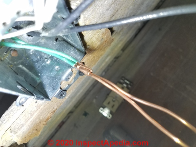
Above you can see that we used a copper crimp connector to bond the incoming and outgoing grounding conductors at the box.
The ground must connect to the metal box by screw or clip as well as to the receptacle's ground connector. If you need the, details are
Above: the new, grounded electrical receptacle is secure in the wall. The plasterer has inserted a bit of house wrap at the upper left side of the box opening to make the plaster repair a bit easier.
Step by step illustrated details for electrical "outlets" properly called electrical receptacles, are
at ELECTRICAL RECEPTACLE CONNECTION DETAILS.
Step 9: install receptacle cover plates and test the circuit
Below: you can see the receptacles, at locations requested by the owner and thus spaced a bit more closely than required by code, in the finished, repaired plaster wall.
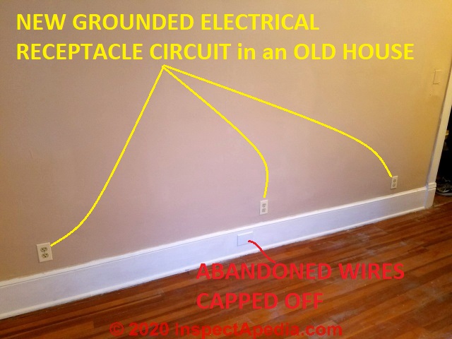
You probably don't need this detail but it's satisfying to put those cover plates onto the newly-added receptacles and then to skip around with your receptacle tester, power now on, to test that each of them is working properly.
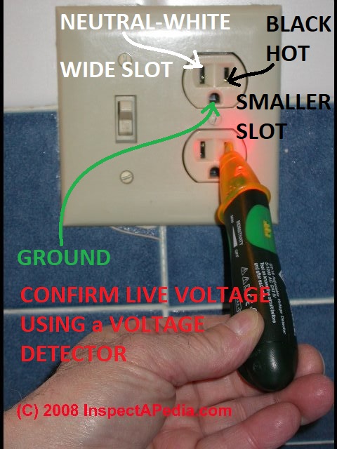
See VOLTS / AMPS MEASUREMENT EQUIP for a description of tools used to detect the presence of live electrical wires & devices and for the measurement of actual volts or amps.
...
Continue reading at OLD WORK ELECTRICAL BOXES for RETROFIT or select a topic from the closely-related articles below, or see the complete ARTICLE INDEX.
Or see these
Recommended Articles
- ELECTRICAL OUTLET, HOW TO ADD & WIRE - home
- 2-WIRE ELECTRICAL RECEPTACLE CONNECTIONS
- ELECTRICAL BOX GROUND WIRING
- ELECTRICAL BOX RELOCATION WIRING
- ELECTRICAL BOX TYPES
- ELECTRICAL DUPLEX RECEPTACLE WIRING
- ELECTRICAL OUTLET HEIGHT ABOVE FLOOR
- ELECTRICAL OUTLET, HOW TO ADD in OLDER HOME
- ELECTRICAL RECEPTACLE CONNECTION DETAILS
- ELECTRICAL RECEPTACLE COVER PLATES
- ELECTRICAL RECEPTACLE HEIGHT & CLEARANCES
- ELECTRICAL RECEPTACLE LOCATIONS
- ELECTRICAL RECEPTACLE POSITION: WHICH WAY UP
- ELECTRICAL SPLIT RECEPTACLE WIRING
- ELECTRICAL RECEPTACLE TYPES
- ELECTRICAL RECEPTACLE WIRING SERIES vs PARALLEL
- GROUND WIRE CONNECTIONS
- NAIL STOPS to PROTECT WIRES
- NUMBER of WIRE CONDUCTORS
- OLD WORK ELECTRICAL BOXES for RETROFIT
- ROUTING, SECURING & PROTECTING ELECTRICAL WIRES
- SIZE of WIRE REQUIRED for ELECTRICAL RECEPTACLES
- SPLICING ELECTRICAL WIRES
- STRIPPING ELECTRICAL WIRES
- ELECTRICAL WALL PLUG WIRING ID & CONNECTIONS
- KNOB & TUBE WIRING
- SAFETY for ELECTRICAL INSPECTORS - home
Suggested citation for this web page
ELECTRICAL OUTLET, HOW TO ADD in OLDER HOME at InspectApedia.com - online encyclopedia of building & environmental inspection, testing, diagnosis, repair, & problem prevention advice.
Or see this
INDEX to RELATED ARTICLES: ARTICLE INDEX to ELECTRICAL INSPECTION & TESTING
Or use the SEARCH BOX found below to Ask a Question or Search InspectApedia
Ask a Question or Search InspectApedia
Share this article:Questions & answers or comments about how to install and wire electrical outlets or receptacles in buildings.
Try the search box just below, or if you prefer, post a question or comment in the Comments box below and we will respond promptly.
Search the InspectApedia website
Note: appearance of your Comment below may be delayed: if your comment contains an image, photograph, web link, or text that looks to the software as if it might be a web link, your posting will appear after it has been approved by a moderator. Apologies for the delay.
Only one image can be added per comment but you can post as many comments, and therefore images, as you like.
You will not receive a notification when a response to your question has been posted.
Please bookmark this page to make it easy for you to check back for our response.
IF above you see "Comment Form is loading comments..." then COMMENT BOX - countable.ca / bawkbox.com IS NOT WORKING.
In any case you are welcome to send an email directly to us at InspectApedia.com at editor@inspectApedia.com
We'll reply to you directly. Please help us help you by noting, in your email, the URL of the InspectApedia page where you wanted to comment.
Citations & References
In addition to any citations in the article above, a full list is available on request.
- Mark Cramer Inspection Services Mark Cramer, Tampa Florida, Mr. Cramer is a past president of ASHI, the American Society of Home Inspectors and is a Florida home inspector and home inspection educator. Mr. Cramer serves on the ASHI Home Inspection Standards. Contact Mark Cramer at: 727-595-4211 mark@BestTampaInspector.com
- [3] NFPA - the National Fire Protection Association can be found online at www.nfpa.org
- [4] The NEC National Electrical Code (ISBN 978-0877657903) - NFPA might provide Online Access but you'll need to sign in as a professional or as a visitor)
- US NEC Free Access: See up.codes at this link: https://up.codes/code/nfpa-70-national-electrical-code-2020
- In addition to citations & references found in this article, see the research citations given at the end of the related articles found at our suggested
CONTINUE READING or RECOMMENDED ARTICLES.
- Carson, Dunlop & Associates Ltd., 120 Carlton Street Suite 407, Toronto ON M5A 4K2. Tel: (416) 964-9415 1-800-268-7070 Email: info@carsondunlop.com. Alan Carson is a past president of ASHI, the American Society of Home Inspectors.
Thanks to Alan Carson and Bob Dunlop, for permission for InspectAPedia to use text excerpts from The HOME REFERENCE BOOK - the Encyclopedia of Homes and to use illustrations from The ILLUSTRATED HOME .
Carson Dunlop Associates provides extensive home inspection education and report writing material. In gratitude we provide links to tsome Carson Dunlop Associates products and services.
 |
HOME | ABOUT | ASK a QUESTION | CONTACT | CONTENT USE POLICY | DESCRIPTION | POLICIES | PRIVACY | |
| © 2026 - 1985 Publisher InspectApedia.com - Daniel Friedman | |||||||||