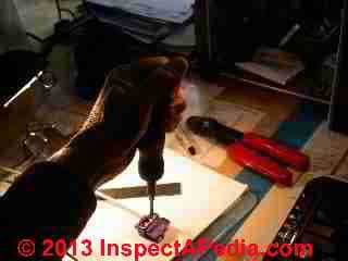
 Comparison of Torque-Setting Methods for the AlumiConn™ splicing connector
Independent test results
- POST a QUESTION or COMMENT about this article topic.
InspectAPedia tolerates no conflicts of interest. We have no relationship with advertisers, products, or services discussed at this website.
- Daniel Friedman, Publisher/Editor/Author - See WHO ARE WE?
Testing AlumiConn™ Splice Connector Torque Test Results
Abstract
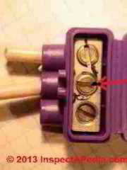
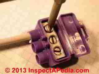
The AlumiConn™ connector shown at left is used to splice a copper "pigtail" wire together with one or two aluminum wires as a step in reducing the fire hazard associated with aluminum electrical wiring.
[Click to enlarge any image]
Our photo (left) shows the bit of a torque screwdriver inserted into the screw in the AlumiConn™ terminal block. Click any image to see an enlarged, detailed version.
Results of independent testing indicate that this product "... is predicted to have a high probability of failure-free long-term safe performance, PROVIDED THAT THE SETSCREWS ARE CAREFULLY TIGHTENED TO THE MANUFACTURER'S RECOMMENDATION".
Reading the UL document recommending use of the AlumiConn™, we found no mention whatsoever of torque specifications - those are particularly important for this particular connector as it involves tightening a screw in a terminal block to secure the aluminum or copper wire being spliced. But as quoted above, Aronstein emphasized that the connector's acceptable performance relied on using the proper torque settings.
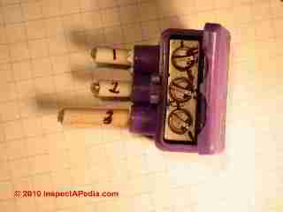 The maufacturer lists two methods for achieving the required splice connector torque, a measure of turning force that in turn reflects how securely the screw is pressed against the wire that has been inserted into the splice terminal block.
- Use a torque measuring screwdriver and set the AlumiConn screw against the electrical wire to 10 inch pounds on aluminum solid conductor wires, or 15 inch-pounds on #10 aluminum or any solid stranded copper wire.
- Use a specified number of turns of the setscrew past "first contact" with the wire in the connector.
We were concerned that there is subjectivity in deciding exactly when "first contact" between the setscrew and the wire has been achieved.
To compare these procedures I (Daniel Friedman for InspectApedia.com) performed simple torque measurement experiments using AlumiConn™ connectors and the SK 73004 torque measuring screwdriver (about $100) provided courtesy of King Innovations.
Results of all tests performed (n=10) showed that the "specified number of turns" method always exceeded the inch-pounds of torque specified by the manufacturer. We conclude that as long as the installer does not so over-tighten a setscrew so as to damage the connector, strip the screw, or excessively compress and damage the wire, this method will meet the required torque specifications.
Watch out: only the measured-torque method of installation is officially a "listed" and CPSC recommended application of the AlumiConn device.
However in an interview of more than 50 licensed electricians conducted by the autor in Dallas TX, not one electrician owned a torque-setting screwdriver measuring in the inch-pounds range and not one electrical supply store had the SK 73004 torque measuring screwdriver in stock. [The product is available online, from the manufacturer, and in some auto supply and hobby stores].
Watch out: For a safe proper installation follow the complete AlumiConn installation instructions provided by the manufacturer and found at
- The AlumiConn website - www.kinginnovation.com/products/alumiconn/ has installation videos, Wire combinations, specification sheets, and other information and assistance in purchasing or using this product.
- The AlCopStore is an independent website where you can also purchase the AlumiConn™ aluminum wiring connector.
A companion discussion, AlumiConn Torque settings, explains why torque is important in electricalconnections & how the necessary torque settings are achieved when installing splices using the AlumiConn™
AlumiConn & SK 73004 torque measuring screwdriver Torque Test Experimental Design
Experiment Objective
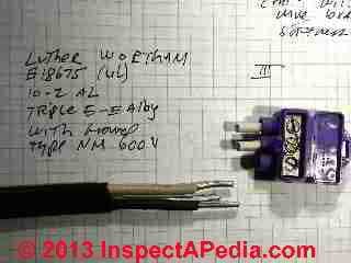 Determine whether or not the turn-count method of torque setting would reach or exceed the measured-torque setting method for the AlumiConn connector.
Equipment & Materials:
- AlumiConn™ connectors provided by the manufacturer
- Aluminum electrical wiring: we used Luther Wortham E18675 (UL) 10-2 AL Triple-E-E Alloy with ground type NM 600V electrical wire provide by Dr. Jess Aronstein.
Because the hardness of single conductor aluminum electrical wires varies by alloy and manufacturer it was important to use the same physical wire alloy for all tests.
For each test, tire was stripped back bare at a length specified by King Innovations for use with the AlumiConn. - Conventional screwdriver
- SK 73004 torque measuring screwdriver
AlumiConn Torque Test 1: Turns past first wire contact
Using AlumiConn splice connectors provided by the manufacturer, we installed both aluminum and copper wires into the connectors.
Using a conventional screwdriver we turned the setscrew until we detected or felt (manually) that the screw requred more force to continue turning at the same rate - defining this as "first contact with the electrical wire".
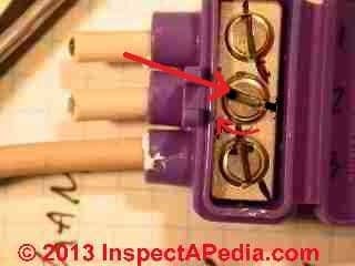
Using a fine felt tip marker we marked the position of the screw head at point of first wire contact. The photo at below left shows the position of the set-screw before attempting to turn it. We marked both the screw head (black dot inside the screw-head slot) and its position in the terminal block.
Using the conventional screwdriver we turned the screw 1/2 or one full tyrn past initial contact as specified by King Innovations. We marked the final position of the screw head at this point.
The photograph above shows the position of the screw after a 1/2 turn using a conventional screwdriver. The arrow indicates the clockwise direction of tightening rotation.
AlumiConn Torque Test 2: Torque to Specified Inch-Pounds using the SK 73004 torque measuring screwdriver
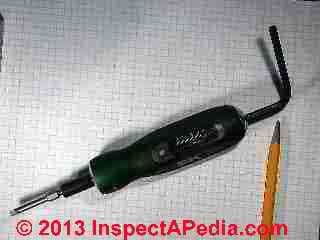 Because the SK™ 73004 torque measuring screwdriver only measured torque in the tightening direction we could not easily use this device to measure reverse torque or loosening force required on the screws set by Torque Test1 above. Instead we performed the following procedure:
Starting with a new AluimiConn™ splice connector and using a conventional screwdriver we turned the setscrew until we detected or felt (manually) that the screw requred more force to continue turning at the same rate - defining this as "first contact with the electrical wire" just as in Test 1.
Using a fine felt tip marker we marked the position of the screw head at point of first wire contact.
Using the SK 73004 torque measuring screwdriver we turned the screw until reaching the 10 or 15 inch-pounds of torque specified by the manufacturer.
We marked the final position of the screw head at this point.
Comparing Torque Tests 1 & 2
By simple visual observation it was easy to compare the final position of the setscrew as torqued by test method 1 and test method 2 above.
If the final position of the set-screw in Test 1 had been turned visibly past the final position of the set screw for the same wire brand and type in the terminal block of the AlumiConn, we concluded that the manual torquing method provide by Test 1 exceeded the measured torqu set by Test 2.
AlumiConn & SK 73004 torque measuring screwdriver Torque Test Experiment Results
Discussion
AlumiConn™ Torque settings specified by King Innovations
- 10 inch-pounds when connecting Solid Aluminum Conductors
- 15 inch-pounds when connecting #10 Solid Aluminum and All Solid or Stranded Copper conductors
- Also see ELECTRICAL SCREW CONNECTOR TORQUE-FORCE for other tests of connection force between wires and binding head screws or clamps.
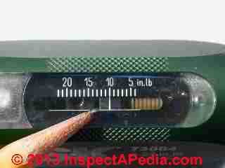
Our photo,left, shows the 15 inch-pound setting on the SK 73004 torque measuring screwdriver [provided courtesy of King Innovations - Ed].
And if you do not have a torque-setting screwdriver King advises: - 1 full turn of the screw past initial contact between screw and wire - for #12 - #10 Solid Aluminum wire
- 1/2 full turn of the screw past initial contact between screw and wire - for #18 - #10 Solid Copper Wire
Finally, King always recommends that installers to check the connection security by giving a quick tug on the wires to make sure they are tight.
Binding of the screw
A difficulty in both subjective measurement of screw-turn resistance and in precision instrument measurement of torque in the same device is that in some electrical components (connector terminal blocks in electrical panels, for example, and in earlier versions of the AlumiConn product) a steel binding-head screw is used in an aluminum terminal block.
The dissimilar metals and manufacturing details can result in the steel screw head binding in the aluminum terminal block due to resistance in the threaded female opening in the block before the required pressure has been obtained between the screw end and the wire against which is supposed to press.
Mr. King informed us that they have addressed this concern by plating the screws in nickel and plating the lug block in tin, thus eliminating the galling found in other lugs. Also there is a very small gap at the back of the wire terminal block where the installer can see the wire (coated in sealant) coming through. This provides visual confirmation that the wires came all the way through.
at LOST NEUTRAL SHOCKS HOMEOWNER - where just this problem occurred, we report a case history of a neutral wire failure, improper joining of neutral and ground wiring in a sub panel, burning-up electrical ground wires, and a homeowner who received a nasty electrical shock.
When I examined that electrical panel I found that the main neutral wire, though properly stripped and inserted into the terminal block, had never been properly connected and could be easily pulled right out of the block by hand. The steel screw had bound in the aluminum block, "fooling" the installing elecctrician.
Using the SK 73004 torque measuring screwdriver
This too is easy to set (an allen key inserted into the end of the handle sets the inch-pounds of torque required) and use (like a normal screwdriver, turn until the device "clicks" like other torque wrench type tools.
It is possible to detect that a screw had not been tightened enough using the manual method, since using the SK73004 on such a screw would result in further turning of the screw.
But the slip-clutch in this tool only operates in the clockwise or tightening turn direction. Therefore it was not possible to use the tool to make a direct measurement of the existing torque of a screw that has already been tightened by a conventional screwdriver for cases in which the screw torque already exceeds the torque setting of the SK 73004.
For this reason we resorted to using actual physical markings to compare screw ending positions.
Based on our tests we conclude that the "alternative method" described by the manufacturer for tightening the screws produces torque close to or exceeding the actual torque specified numbers (according to some preliminary tests we have done in our lab) - photo at left.
But we are not completely confident that that approach would be adequate for general field use where individual human performance may vary considerably.
For example, you may not be exactly sure just when the setscrew "... comes into contact with the solid conductor". King is confident of this approach but is careful to point out that it is not associated with the UL listing for the product.
Conclusions
In every test conducted on both aluminum and copper wire and the AlumiConn splice connector for aluminum wire repair, we found that the manual method (Test 1) always produced more torque (more screw turns) than the measured torque method (Test 2).
The manufacturer's advice to tug to check the security of wires adds an additional measure of security against under-tightening of the setscrew. And the absence of any field reports of field-failures of the AlumiConn splice connector in service (though early in the product life) adds confidence to its performance, with the caveat that absence of evidence is not evidence of absence of failures in any device or study.
Further study on a larger number of devices in lab or field tests and making use of an instrument that can measure reverse or loosening torque resistance could improve the confidence of our initial findings.
Watch out: the manufacturer makes clear that their installation instructions for the AlumiConn without using a torque-setting screwdriver are not included in the CPSC recommendations, but the " manufacturer (King Innovation) stands firmly behind this installation method." [1]
Other Splicing Connectors Tested for Use with Aluminum Wire - jury remains out
WALL-NUTS [New U.S. product application, Not UL Listed, undergoing testing before UL application] spring-clamp terminal blocks available from Wago Corporation have is being tested by that company for
a connector for aluminum-to-copper pigtailing for aluminum wiring repair.
The company informs us that a similar product
use with aluminum wire conductors has been approved and used in Europe for over 20 years.
See details at WAGO WIRE SPLICING CONNECTORS
...
Reader Comments, Questions & Answers About The Article Above
Below you will find questions and answers previously posted on this page at its page bottom reader comment box.
Reader Q&A - also see RECOMMENDED ARTICLES & FAQs
On 2021-06-04 by inspectapedia.com.moderator (mod) - there should be no case where a solid conductor aluminum branch circuit wire is not pigtailed to Copper
@Chris,
Please see our discussion about this at at ALUMINUM WIRING REPAIR FIELD NOTES
On 2021-06-04 by Chris
Hi, I have a house built in 71 with 10 gauge aluminum wire. ... I have purposefully been skipping any signal aluminum wire to goes directly and only to a light fixture.
My entire house is LED and feel like it won't carry much of a load.
I make sure that the aluminum connections is secure to the light switch, but skip adding AlumiConn just for those specific connections... "for now".
How risky is this? I feel like the biggest risk is connections carrying a load to another and have been focusing on those type of connections.
...
Continue reading at ALUMINUM WIRING REPAIR FIELD NOTES, or select a topic from the closely-related articles below, or see the complete ARTICLE INDEX.
Or see these
Recommended Articles
- ALUMINUM WIRING HAZARDS & REPAIRS - home
- ALUMINUM WIRING REPAIR METHODS
- ALUMINUM WIRING REPAIR ELECTRICIANS
- ALUMINUM WIRING REPAIR METHODS - CPSC Meeting 9/28/95
- ALUMINUM WIRING REPAIRS NOT-RECOMMENDED
- REDUCE THE AL WIRE RISK: DETAILS
Suggested citation for this web page
AlumiConn TORQUE TESTS at InspectApedia.com - online encyclopedia of building & environmental inspection, testing, diagnosis, repair, & problem prevention advice.
Or see this
INDEX to RELATED ARTICLES: ARTICLE INDEX to ELECTRICAL INSPECTION & TESTING
Or use the SEARCH BOX found below to Ask a Question or Search InspectApedia
Ask a Question or Search InspectApedia
Try the search box just below, or if you prefer, post a question or comment in the Comments box below and we will respond promptly.
Search the InspectApedia website
Note: appearance of your Comment below may be delayed: if your comment contains an image, photograph, web link, or text that looks to the software as if it might be a web link, your posting will appear after it has been approved by a moderator. Apologies for the delay.
Only one image can be added per comment but you can post as many comments, and therefore images, as you like.
You will not receive a notification when a response to your question has been posted.
Please bookmark this page to make it easy for you to check back for our response.
IF above you see "Comment Form is loading comments..." then COMMENT BOX - countable.ca / bawkbox.com IS NOT WORKING.
In any case you are welcome to send an email directly to us at InspectApedia.com at editor@inspectApedia.com
We'll reply to you directly. Please help us help you by noting, in your email, the URL of the InspectApedia page where you wanted to comment.
Citations & References
In addition to any citations in the article above, a full list is available on request.
- AlumiConn website - www.kinginnovation.com/products/alumiconn/ has installation videos, Wire combinations, specification sheets, and other information and assistance in purchasing or using this product.
- [1]AlumiConn [Website: AlCopStore.com ] ™ AlCopStore.com
223 Salt Lick Road, #279,
St. Peters, MO 63376
Tel: 866-826-2256, Fax: 636-754-0500, Email Sales: pking@AlCopStore.com, Email General Inquiry: info@AlCopStore.com - [2] "Repairing Aluminum Wiring," [As updated 2011] U.S. Consumer Product Safety Commission Publication available online
- [3] "Record of Commission Action, Commissioners Voting by Ballot", CPSC Publication No. 516, Repairing Aluminum Wiring (original version op.cit.), (Briefing package dated March 15, 2011), Quoting:
The Commission voted unanimously (5-0)·to approve republication of CPSC Publication No. 516, Repairing Aluminum Wiring, with the explicit recognition that the COPALUM and AlumiConn connectors currently are the only products that meet the agency's standards to prevent aluminum wire fire hazards
Copy on file as /aluminum/Pub516_Alumi_Conn.pdf - [4] Dr. Jess Aronstein, protune@aol.com is a research consultant and an electrical engineer in Schenectady, NY. Dr. Aronstein provides forensic engineering services and independent laboratory testing for various agencies. Dr. Aronstein has published widely on and has designed and conducted tests on aluminum wiring failures, Federal Pacific Stab-Lok electrical equipment, and numerous electrical products and hazards.
- [5] "The Influence of Corrosion Inhibitor and Surface Abrasion on the Failure of Aluminum-Wired Twist-on Connections", Aronstein, J.; Campbell, W., Components, Hybrids, and Manufacturing Technology, IEEE Transactions on Volume 7, Issue 1, Mar 1984 Page(s): 20 - 24
- "Aluminum Wiring: Understanding the Problem and Its Solutions", Hartford Insurance Company - NOTICE: this information contains technical errors and some obsolete information. We include the document reference as an indication of insurance companies who are aware of aluminum electrical wiring hazards and costs. Local copy.
- 05/21/2007 Reducing the Fire Hazards in Aluminum-Wired Homes, [.pdf document], Jess Aronstein, Ph.D., 21 May 2007. This document answers most technical questions about the hazards and remedies of aluminum electrical wiring and includes
a report on independent test results of alternative products and methods for repairing aluminum wiring. Some of the sections of this very thorough document are listed below:
- WANTED: Aluminum Wiring Field Reports, Photographs, Samples, & Failure Cases & Data for ongoing study on frequency and severity of occurrence of problems.
If you have experienced any problem, or symptom of possible problem with aluminum electrical wiring, or have repaired or replaced it, please contact the InspectApedia Editor All information is confidential.
Study results will be provided to the U.S. Consumer Product
Safety Commission and to the electrical industry. Real life aluminum wiring field failure reports can be seen
at Aluminum Wiring Failures in Residential Properties: Field Reports & Pictures. - In addition to citations & references found in this article, see the research citations given at the end of the related articles found at our suggested
CONTINUE READING or RECOMMENDED ARTICLES.
- Carson, Dunlop & Associates Ltd., 120 Carlton Street Suite 407, Toronto ON M5A 4K2. Tel: (416) 964-9415 1-800-268-7070 Email: info@carsondunlop.com. Alan Carson is a past president of ASHI, the American Society of Home Inspectors.
Thanks to Alan Carson and Bob Dunlop, for permission for InspectAPedia to use text excerpts from The HOME REFERENCE BOOK - the Encyclopedia of Homes and to use illustrations from The ILLUSTRATED HOME .
Carson Dunlop Associates provides extensive home inspection education and report writing material. In gratitude we provide links to tsome Carson Dunlop Associates products and services.


