
InspectAPedia® FREE Encyclopedia of Building & Environmental Construction, Diagnosis, Maintenance & Repair |
Question? Just ask us! InspectAPedia
|
 Electric Motor Troubleshooting
Diagnose & Repair Electric Motors on Building HVAC Equipment

- POST a QUESTION or COMMENT about how to troubleshoot electric motors such as air conditioning compressor motors, heating equipment burner or fan motors, swimming pool motors, water well pump motors
Electric motor test & repair guide:
This article describes A/C electrical motor troubleshooting: an electric motor diagnostic table and a troubleshooting guide to diagnose and repair most electric motor problems such as electric motors used in air conditioners, furnace or air handler blower fans, oil burner motors, vacuum cleaners, power tools, well pumps, and condensate return pumps.
InspectAPedia tolerates no conflicts of interest. We have no relationship with advertisers, products, or services discussed at this website.
- Daniel Friedman, Publisher/Editor/Author - See WHO ARE WE?
A/C Electric Motor Troubleshooting Guide - Test Procedures
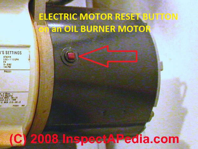
 In this article we provide a diagnostic guide to determine and repair problems with electric motors. The page top photo was taken of of an oil burner electric motor not an air conditioning blower fan motor or pump motor, but you'll see that all of these electric motors look a lot alike.
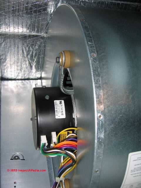
At left our photo illustrates the motor as typically found in a direct-drive HVAC blower or air handler assembly. More about this air handler fan i
s at BLOWER FAN OPERATION & TESTING.
[Click to enlarge any image.]
Watch out: if you are not trained in safe electrical wiring and test tool use you should not fool with electrical motors or wiring. You could be shocked or killed.
Article Series contents
- A/C ELECTRIC MOTOR COMPONENTS
- DMMs VOMs SAFE USE OF
- DO IT YOURSELF ELECTRICAL WORK
- ECM MOTOR CAUSING CIRCUIT BREAKER BUZZ - blower motor troubleshooting
- ELECTRIC MOTOR DATA TAG
- ELECTRIC MOTOR CENTRIFUGAL SWITCH or PTC PRD - bad switch, motor won't start
- ELECTRIC MOTOR OVERHEATS - 7 things to check
- ELECTRIC MOTOR RUN DIRECTION
- ELECTRIC MOTOR START SWITCH
- ELECTRIC MOTOR TYPES - 8 types of single phase, split phase, 2 & 3 phase motors
- ELECTRIC MOTOR WON'T START / RUN - 14 Things to Check
- ELECTRIC MOTOR OFF on RESET
- ELECTRIC MOTOR TESTS - Electrical Tests to Check HVAC Blower Fan Motor or Outdoor Compressor Fan Motor Winding on Heating or Cooling Equipment or on Other Electrical Motors
- ELECTRIC MOTORS, 3-PHASE
- ELECTRIC MOTOR LIFE
- ELECTRIC MOTOR WIRING DIAGRAMS & GUIDES
While our page top photo shows the red reset button most clearly, the reset button on the motor at left may be harder to spot. Sometimes the reset button on an electric motor is hard to find, and sometimes there is no reset button!
Fatal Shock Hazard Warning: Inspecting electrical components and systems risks death by electrocution as well as serious burns or other injuries to the inspector or to others. Do not attempt these tasks unless you are properly trained and equipped.
See DMMs VOMs SAFE USE OF for help in making safe use of electrical test equipment before you start poking your meter probes into anything.
...
Basic Components of an A/C Electric Motor such as used on heating and air conditioning equipment
Before discussing how to diagnose air conditioner or heating system electric motors let's be sure we know what motor parts might be involved. (Or skip right to Table A if you prefer).
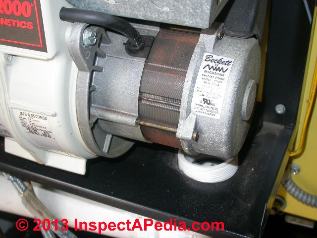 Photo: electric motor on a modern oil burner.
The electric motor has quite a few parts if examined in detail, switches, wires, possibly capacitors, oiling ports and more, but there are four basic parts to every HVAC electric motor:
- Electric motor rotor: the rotor follows (turns in the direction impelled by) the rotating magnetic field and thus spins the motor shaft
- Electric motor stator: the stator consists is a device or core containing start and run windings (of copper wire) wound around a central core to create a magnetic field.
- Electric motor windings: the two windings are used to create an electrical field in the stator.
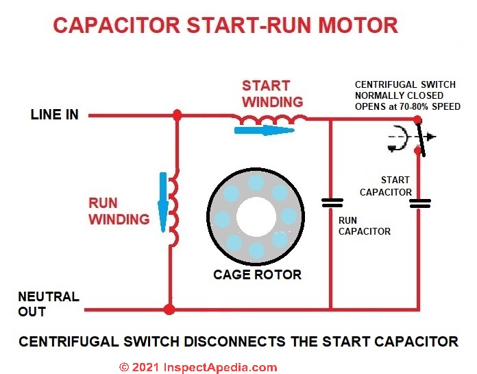
- Definition of Start winding: in an A/C (alternating current) electric motor electrical current flowing through the start winding is used just to get the motor spinning from a stopped condition.
The start winding is disconnected, usually by a centrifugal switch, when the motor is up to speed. - Definition of Run winding: in an A/C electric motor the run winding is what keeps the motor spinning once it has started.
Current flowing through this winding produces a rotating magnetic field in the stator that keeps the motor shaft turning after the start winding has turned off.
- Definition of Start winding: in an A/C (alternating current) electric motor electrical current flowing through the start winding is used just to get the motor spinning from a stopped condition.
- Electric motor start switch: a centrifugal switch connects the A/C electrical power to the motor to the start winding on the stator until the motor has reached a speed typically of 75-80% of its full run speed (typically that's1725 rpm or 3450 rpm on newer high-speed oil burners).
In addition to the basic electric motor components above there are two other features to know about when troubleshooting a motor.
...
How to Read the Information on an Electric Motor Data Tag
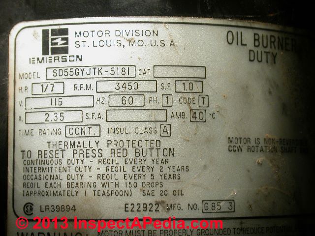 In our photo at left you can see the notation on this electric motor data tag indicating the the motor is non-reversing and rotates counter-clockwise - designated by the words CCW ROTATION (red arrow).
If you enlarge the photo [Click any image to see an enlarged, detailed version] you will see text above the red arrow noting that this is a NON-REVERSING motor.
See ELECTRIC MOTOR RUN DIRECTION
The blue oval marks the motor's rotating speed - 3450 RPM - this is a high speed oil burner. Older oil burners and equipment motors run at 1725 RPM.
Some HVAC equipment uses a variable-speed electric motor, often an ECM or “electronically commutated motor” that uses electronic controls to control and/or to vary the motor speed.
The green rectangle marks other useful data in the data tag for this motor, made by Emerson Electric in St. Louis MO. This is a 1/7 hp motor, designed for 115VAC, drawing 2.35A.
These data are helpful when diagnosing electric motor problems: using a DMM or VOM we can detect unusual current draw above that 2.35A as a sign of trouble and we can check that the voltage level delivered by the electrical supply is close to 115VAC 60 cycle current single phase.
The motor's model number (SD55GYJTK-5181 in this example) is useful when replacing the motor or contacting the manufacturer for assistance.
An Electric Motor Time Rating designation is specified as CONT (continuous duty) - this motor is able to run continuously without damage or overheating under normal conditions.
A temperature rating (40C) and other data are given as well, including an explanation that this motor is. thermally protected and that should the motor's thermal protection switch trip off the user needs to press the red button.
See ELECTRIC MOTOR OVERLOAD RESET
This motor's data tag also includes oiling specifications indicating the required lubrication schedule, discussed
Tips for Buying a Replacement Electric Motor
Watch out: when buying replacement electric motors, fuel units, and blower fan assemblies to be sure they all are compatible.
For example on oil fired heating equipment, the oil burner fuel units (the mechanical heating oil pump driven by the oil burner electric motor via a coupling) can be purchased as CW or CCW devices. All three components have to be designed to rotate in a common direction:
- the electric driving motor,
- the oil burner combustion air blower fan assembly, and
- the oil burner fuel unit or oil pump.
If the fuel unit is not rotated in the proper direction the heating appliance won't run - it won't receive fuel, and the driving motor and coupling parts may be damaged.
If a squirrel cage blower fan on an oil burner or inside of an air handler is spun backwards it will not move much air and equipment will not function properly.
See ELECTRIC MOTOR RUN DIRECTION
Watch out: when ordering a replacement ECM variable speed motor, such as a constant torque variable speed ECM motor often used in HVAC equipment you should take care to match the specifications of the original motor.
The programming of the electronic control module that controls the motor speed and torque is done at the factory - it's not something you adjust in the field.
Electric Motor Lubrication Specifications & Schedules: when, how much oil, where to oil
For article loading speed we have moved this data
Electric Motor Thermal Overload Switch - the Thermal Switch
Details are at ELECTRIC MOTOR OVERLOAD RESET - separate article.
...
Electric Motor Start Switch Operation in Electric Motors
The start switch connects power to the start winding to start the motor spinning. This feature is necessary because depending on the position in which the rotor stopped when the motor last turned off, the rotating electrical field created by the run winding can't start the motor.
At CAUSES of HARD STARTING ELECTRIC MOTORS we explain how a failed starting capacitor OR depending on the motor design, a bad centrifugal switch can prevent a motor from starting.
A trained service technician may sometimes diagnose a failed start winding or failed start switch (centrifugal switch) by spinning the motor manually (potentially dangerous!). If the motor keeps running we suspect a bad start winding or bad start switch (see diagnostic table details
at Table A: 14 THINGS to CHECK (in order) if an A/C Electric Motor Will Not Start.
When the electric motor has reached about 75-80% of its full speed the centrifugal switch opens, thereby disconnecting AC electrical power from the start winding. Power was already connected to and remains connected to the run winding.
So if the motor will start but won't keep running, we suspect a bad run winding or bad wiring to the winding.
For electric motors used in most HVAC applications motor full speed is usually 1725 or 3450 rpm, though some equipment may use variable speed motors as well.
The centrifugal switch will open ("throwout") at about 2800 rpm for a 3450 rpm electric motor, and the centrifugal switch will open at about 1400 rpm for a 1725 rpm electric motor.
See more details at ELECTRIC MOTOR CENTRIFUGAL SWITCH or PTC PRD
...
Sparking Electric Motor Repair
Some sparking is normal within many electric motors including, for example, many table saws and drills, but no sparks ought to be seen exiting the device or its motor for obvious safety reasons.
Typically when I've seen sparks spraying out of a drill or table saw I've found that the motor brushes need replacement.
A burned commutator in the electric motor is often the root problem.
Some light cleaning of the commutator may be needed.
Take care not to score it.
Remove the motor armature and sand it with very fine emery paper. Inspect the armature while cleaning it
- If you see score or burn marks those need to be removed - otherwise the new brushes in the motor will not last long.
- If you cannot clean the copper armature sufficiently to remove scores and burns without sanding through the copper surface completely (I'd like to see at least 1/16" remaining copper) then the part needs replacement.
- When you've finished cleaning the copper armature surface that contacts the motor brushes should be both shiny and very smooth. Replace the motor brushes while you're at it.
- When replacing the armature be SURE that you don't leave grit on the parts or in the bearings or you'll probably ruin the motor.
While you're at it feel for side play when replacing this part - which may indicate worn-out bearings in the motor mount.
...
Basic Electric Motor Designs
Not all Electric Motors use a Starting Capacitor and/or Centrifugal Switch: here we describe (in oversimplified terms) 8 Common Electric Motor Designs.
Single Phase Electric Motors
- Single phase, capacitor-start, capacitor-run motors:
Many single-phase electric motors may use a start and run capacitor to get the motor running and keep it running smoothly. The start winding and start capacitor are cut-out as the motor approaches full speed. - Single phase, capacitor-start, capacitor-run, aux winding run motors:
Some single phase electric motors use a centrifugal switch to cut out the starting capacitor but keep the start winding in use as an aux winding as the motor gets up to speed. - Single-phase, no centrifugal switch:
Other single phase motors have no centrifugal switch. When the motor reaches it full running speed the auxiliary winding remains in use, causing the unit to run as if it were a two-phase motor. This is considered a particularly-reliable electric motor design.
Split-Phase Electric Motors
 Split-phase motors divide a single electrical current phase, sending it through two different windings that produce an electrical effect similar to motors run by a two-phase current source, producing a rotating electrical field to turn the motor.
- Split-phase, capacitor-start, capacitor-run electric motors
require both a starting capacitor and a smaller run capacitor. Usually a centrifugal switch is used to cut-out the starting capacitor as the motor approaches its full running speed. The run cap remains active. - Split-phase, capacitor-start, induction run motors
use a starting capacitor but do not use a run capacitor. Usually a centrifugal switch is used to cut-out the starting capacitor as the motor approaches its full running speed. - Split phase, resistance-start, induction-run motors
do not use starting nor run capacitors.
In a resistance-start induction-run electric motor, an out-of-phase condition occurs because the start-winding has higher electrical resistance than the run winding. For these motors, starting torque is created by the combination of the stator's magnetic field strength, the rotor's magnetic field strength, and the angle by which the two currents are out of phase with one another.
The theoretical maximum torque would occur at 90° out of phase but actually inductive resistance differences between the thinner start winding and thicker run winding will typically produce a phase angle difference between 35° and 40° - not not enough to give a strong starting torque.
Multi-Phase: 2-phase or 3-Phase Electric Motors
Still other electric motors use the rotating magnetic field produced a two-phase or three phase design both to start the motor and to keep it spinning.
- 2-phase motors use two separate windings oriented at 90° from one another, "out of phase" with one another, to produce a rotating magnetic field to turn the motor.
- 3-phase motors use three separate windings out of phase with one another, also producing a rotating magnetic field to spin the motor.
In a split-phase motor the stator uses two separate windings: start winding (smaller diameter wire) and a run winding (larger diameter wire). The start winding has higher electrical resistance than the run-winding, and it will be close to the top of the stator's core.
The run winding will be located near the bottom of the stator and will have the lower resistance of the two windings. The two windings are connected electrically in parallel with one another, as you can see in our sketch.
This type of stator can be used in both capacitor-start, capacitor run motors and in capacitor-start, induction-run motors.
The electric motor's stator contains four electrical poles, and the start winding is always located at 90° from the run winding. As electrical power is turned-on to the stator current will flow through both the start and run winding at the same time, but because of the higher resistance of the start winding, its current flow is more in-phase with the source voltage than will be the current flow through the run winding.
Therefore, the current flowing through the run-winding will lag behind the current flow through the start winding (due to inductive resistance).
It is the fact that there are then two flowing currents that are out of phase with one another that a rotating magnetic field is created in the stator.
The rotation speed of the magnetic field depends on the number of poles in the stator and the frequency of the source voltage (e.g. 60hz or 50hz). Several sources give a simple formula for determining an electric motor's rotating speed:
Speed = 120 x Frequency / Number of Stator Poles, or S = F/P.
Using the U.S 60Hz standard, we can calculate that a 2 pole motor should spin at 3600 rpm. (S or 3600 = 120 x 60 / 2)
...
Electric Motor Diagnostic Tests
How to Check HVAC Blower Fan Motor or Outdoor Compressor Fan Motor Winding on Heating or Cooling Equipment or on Other Electrical Motors
1. Simple Electric Motor Resistance Tests: Leads
Testing a blower fan motor winding: referring to the electrical diagram for your equipment, unplug electrical connectors at the fan motor.
Measure the resistance between each lead wire with a multimeter or VOM. The multimeter should be set in the X1 range.
For accuracy, don't measure when the fan motor is hot, allow it to cool off.
- When the resistance between each lead wire are those listed in the specifications for your equipment the fan motor should be normal.
- Zero resistance or infinite resistance are indicators of a problem .
2. Simple Electric Motor Resistance Tests: Windings
Test to determine if a motor winding (start winding or run winding) is not broken (open) or shorted (closed).
This test can be done on most household appliance motors including both single-phase and three-phase electric motors.
With the VOM set to the most-sensitive resistance or ohms scale (R x 1), and with the meter zeroed, check the resistance between the motor winding leads (you may need to check the motor's wiring diagram to be sure you're checking in the right spot).
- Normal:
You should see low resistance, less than 10 ohms. That's normal. - Zero or very low resistance:
You should not see very low resistance, close to zero. That suggests a shorted winding. The motor will probably blow a fuse or trip a circuit breaker when turned-on.
Very low resistance between a motor wiring terminal and the motor's metal case,
that can mean that there is a short between a motor terminal and ground, probably through the motor's steel casing.
No resistance between the start and run terminals to common,
but resistance between the start and run terminals, this means that the internal motor overload protection circuit is open. In this last case, allow the motor to cool and re-test it before replacing it. - Resistances over 10 ohms.
If you see infinite resistance the winding has probably burned or broken.
Higher resistance readings probably mean that the winding is damaged while very high resistance readings or infinite resistance tell you that a winding is broken or "open".
Watch out: when measuring resistance at very low levels, a poor connection with your probe or even having your finger in the circuit will foul up the reading's accuracy.
Watch out: some damaged motor windings will test out just fine on the bench with the motor disconnected completely, but when the motor begins to spin a damaged wire in the winding may, due to the centrifugal force of rotation, open, causing the motor to run poorly or to stop completely or to chatter.
More detailed VOM tests on motor leads and windings are given in our diagnostic table found
at ELECTRIC MOTOR DIAGNOSTIC GUIDE
At BASIC ELECTRICAL TESTS for BURNED OUT COMPRESSOR MOTORS we give more details about resistance levels to expect when testing an electric motor.
3. Check electric motor start / run capacitors
If your motor uses a start/run capacitor, the capacitor could be defective.
If inspection by eye shows a capacitor that is bloated, burned, deformed, it needs to be replaced.
If by eye the capacitor looks ok it might still be defective.
With the capacitor disconnected from the motor's wiring, with your VOM probes on the cap's leads (test start and common, then run and common separately if the cap is a combined start/run device) you will see the resistance rise from a low number as the capacitor begins to charge, driven simply by the power source in your VOM itself.
Watch out: let the capacitor bleed-down for 10-15 minutes before trying to repeat this test or, as it still holds a charge your test will be in-valid.
See details
at TEST a MOTOR START or RUN CAPACITOR
More electric motor diagnostic guides and downloads are
at ELECTRIC MOTOR WIRING DIAGRAMS & GUIDES
and in theReferences or Citations section of this article
4. Check the Electric Motor's Centrifugal Switch
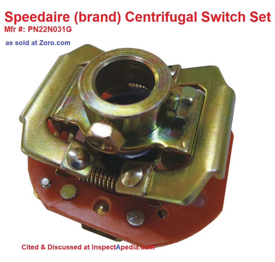
Typically a centrifugal switch or possibly a PTC or PRD drops the start capacitor from the motor's electrical circuit once the motor has spun up to operating speed, or in some designs, a mechanical centrifugal switch may be used to disconnect the starting capacitor when the motor speed has reached a critical rpm, typically about half of the motor's run speed.[2]
If your electric motor uses a centrifugal switch to cut out the "start" capacitor once the motor is up to speed, a failure of that switch can cause motor failure.
Diagnostic details for a centrifugal switch used on electric motors are
at ELECTRIC MOTOR CENTRIFUGAL SWITCH or PTC PRD
5. Check the electric motor's cooling fan
If your electric motor is an "open" design you can see into the motor housing; look for clots of dust and oil that may be blocking the cooling fan and causing the motor to overheat; overheating can cause the motor's thermal overload switch to shut the motor off (and the switch may pop out waiting to cool-down and re-set).
See details
at ELECTRIC MOTOR OVERLOAD RESET
5. Electric Motor Circuit Analysis - MCA
Excerpting from Andy Page, The BASICS of MOTOR CIRCUIT ANALYSIS [PDF] Reliable Plant, (Noria Corporation), 1328 E. 43rd Court, Tulsa, OK 74105
Tel: 800-597-5460; Email: pagea@alliedreliability.com, retrieved 9/13/12, original source: http://www.reliableplant.com/Read/10686/motor-circuit-analysis, Excerpt:
MCA online [tests performed while the motor is operating] can be further split into two categories - current analysis and voltage analysis.
Current analysis is primarily focused on the rotating components. Loose or broken rotor bars, cracked end rings, rotor eccentricity, misalignment and coupling/belt problems are some of the "big-hitter" failure modes detected in the current signature.
Power quality issues like harmful harmonics, voltage imbalances and under/over-voltages are among the issues identified with voltage analysis.
MCA offline is most famous for the resistance-to-ground measurement. But other measurements make motor circuit defects easy to find.
Measuring electrical characteristics like impedance, inductance and capacitance tell the analyst plenty about the condition of the windings.
Inductance is a great indicator of turn-to-turn shorts. Capacitance to ground measures the amount of winding contamination (water, dirt, dust, etc.).
Changes in each of these affect impedance (total resistance of an AC circuit). These characteristics are measured phase to phase and phase to ground and compared to each other and to percent change from baseline to identify motor circuit defects.
Motor circuit analysis (MCA) is often and easily confused with motor current analysis (MCA), which is an abbreviated version of motor current signature analysis (MCSA).
Repair Article Recommendations by System Type
- Air conditioning or heat pump systems: to locate the various controls and switches for A/C or heat pump systems
see CONTROLS & SWITCHES, A/C - HEAT PUMP.
Also see THERMOSTATS, HEATING / COOLING. - Heating systems: If you are looking for the main burner reset button on heating equipment you'll want to
see: Aquastat Functions
and Cad Cell Relay Switch Flame Sensors (hot water boilers and some water heaters),
STACK RELAY SWITCH On older oil fired boilers and furnaces,
FLUE GAS SPILL SWITCH TRIPPING & RESET (gas fired equipment), and
LOW WATER CUTOFF CONTROLS On steam heating systems.
Condensate pump motors on steam heating systems are also discussed
at CONDENSATE RETURN PIPES, PUMPS, STEAM - Thermal overload relays on electric motors used on air conditioning, heating, water supply and other building equipment may shut off an overheated motor and (if not automatic) may require a manual reset.
See ELECTRIC MOTOR OVERLOAD RESET SWITCH explanation (how to reset a motor off on reset). - Water supply systems: Controls on well pumps and water supply equipment that may require reset or repair are discussed
at CONTROLS & SWITCHES on WATER TANKS.
...
Typical Life of an Electric Motor
Why Do we Get Repeated Electric Motor Failures?
Our reader asked:
I had a 3 ton Trane Package unit installed less than 3 years ago from a reputable company in Miami, FL. In less than 3 years, my blower motor had to be replaced twice. To me, that sounds crazy and like something is just not right either with the unit or the install
Company says its due to humidity / environmental conditions etc. I live in Miami my whole life, never remember any other AC units needing a new blower motor yearly. Is this normal behavior for a practically new AC? On 2019-02-19 by Moshe -
Repeated failures of Trane blower motor
We replied: I agree with you that the behavior sounds abnormal. There might be something in the local environment such as unusual moisture or even corrosive gases, or low voltage, or some other installation issue that could be a factor.
Certainly plenty of blower motors run in daily use for decades. Let's both do some research on electric motor failure rates as a function of climate such as Florida. And let's both report back here
Research on Electric Motor Life Expectancy
- Brancato, Emanuel L. "Estimation of lifetime expectancies of motors." IEEE Electrical Insulation Magazine 8, no. 3 (1992): 5-13.
Abstract;
Methods for evaluating lifetime expectations are discussed. Factors that affect the life of bearings and brushes and of wire coil insulation are identified.
Thermal life of insulation and methods for accelerated testing are discussed.
Examples are included to assist in the calculation of such factors as motor temperature-rise conditions and the benefits to be realized through upgrading the thermal classification of the motor insulation system. - Cheung, G. S. P., and B. W. Darvell. "Fatigue testing of a NiTi rotary instrument. Part 1: strain–life relationship." International endodontic journal 40, no. 8 (2007): 612-618.
- De Kleine, Robert D., Gregory A. Keoleian, and Jarod C. Kelly. "Life cycle optimization of residential air-conditioner replacement." Ann Arbor: University of Michigan (Retrieved from Center for Sustainable Systems, Report No. CSS10-02) (2010).
- Henderson, H. I., & Sachs, H. M. (2006). The Efficacy of SEER as a Seasonal Performance Measure
for Different Climates. Symposium on Improving Building Systems in Hot and Humid
Climates (ESL‐HH‐06‐07‐40). - Hamilton, Robert John. "DC motor brush life." IEEE Transactions on Industry Applications 36, no. 6 (2000): 1682-1687.
- Kimura, K., T. Iwabuchi, K. Morooka, and Y. Ishikawa. "Fundamentals-a useful index for estimating residual life of motor insulation." IEEE Electrical Insulation Magazine 6, no. 2 (1990): 29-32.
- Hamilton, Robert John. "DC motor brush life." In Conference Record of 1998 IEEE Industry Applications Conference. Thirty-Third IAS Annual Meeting (Cat. No. 98CH36242), vol. 3, pp. 2217-2224. IEEE, 1998.
...
Electric Motor Wiring & Diagnostic Guides: Wiring Diagrams, Parts, Repair Guides
Watch out: if you are not trained in proper, safe electrical work, stay out of your electric motor - you could be shocked or killed.
- Baldor INSTALLATION, OPERATION AND MAINTENANCE OF RELIANCE® STANDARD INDUSTRIAL AC INDUCTION MOTORS - [PDF] Baldor Electric Company
P.O. Box 2400
Ft. Smith, AR 72902-2400 USA Tel:
(501) 646-4711
book of wiring diagrams for the same series of motors produced later under Baldor - Baldor, BALDOR MOTOR CHART [PDF], NEMA Quick Reference Chart to NEMA Frames & Motor Properties, Brownell Motors and Drives
- Baldor, BC254 REGEN DC MOTOR SPEED CONTROL INSTALLATION AND OPERATING MANUAL [PDF] (2001) Baldor Electric Co., - retrieved 2021/04/04 original source: https://www.baldor.com/Shared/manuals/730.pdf
- BASIC ELECTRICAL TESTS for BURNED OUT COMPRESSOR MOTORS
- BETTA-FLO JET PUMP INSTALLATION MANUAL,[PDF] National Pump Company, 7706 North 71st Ave., Glendale, AZ 85303, Tel: (800) 966-5240 Email: info@natlpump.com, website: http://www.nationalpumpcompany.com, retrieved anew 9/13/12, original source: http://www.nationalpumpcompany.com/pdf/Betta_Flo_IOM_Jet_Pump.pdf
- BODINE ELECTRIC MOTOR CATALOG & MANUAL [PDF] NR-2 - Bodlne Electric Company 2500 W Bradley Place Chicago. lllmo~s 60618
- BODINE GEARMOTOR HANDBOOK [PDF] Op. Cit., Small gear motors, motors, and controls, 5th Ed.
- BROWNELL MOTOR REPAIR PARTS CATALOG [PDF] Essex Brownell, Essex Group, Inc., 1601 Wall St., Fort Wayne IN 46801 USA, Website: www.superioressex.com Tel: 800-774-4643
- Burt, Charles M., Xianshu Piao, Franklin Gaudi, Bryan Busch, and N. F. Taufik. ELECTRIC MOTOR EFFICIENCY UNDER VARIABLE FREQUENCIES AND LOADS [PDF] Journal of irrigation and drainage engineering 134, no. 2 (2008): 129-136.
Abstract:
This paper details a study performed by the Irrigation Training and Research Center to determine motor performances under varying speeds [induced by a variable frequency drives (VFD) controller] and loads.
A further goal of the study was to provide sufficient information to designers so that they could estimate total pumping plant power usage with a VFD-controlled installation.
Motors were tested with a VFD as well as across-the-Iine. On average, the relative efficiency of the electrical system with a VFD may be approximately 8% lower than the relative efficiency of a properly designed, full-load across-the-line system.
If one considers actual field operating conditions this 8% is misleading because overall energy savings can be obtained with VFDs due to their ability to properly adjust speeds to meet actual field conditions. - Capacitor Industries, DIFFERENCE BETWEEN RUN AND START CAPACITORS [PDF] Capacitor Industries | 335 Beinoris Drive, Wood Dale, Illinois, 60191 | 773-774-6666 (phone) | 773-774-6690 (fax) | www.capacitorindustries.com, retrieved 2022/08/05, original source: https://www.capacitorindustries.com/wp-content/uploads/Run-and-Start-Capacitors.pdf
Excerpt:
The simplest way to explain the mechanics of a capacitor would be to compare it to a battery; both store and release electricity. Capacitors are charged with electricity then release its stored energy at a rate of sixty times per second in a 60 cycle alternating current system.
The sizing is critical to motor efficiency just as sizing of batteries is critical to a radio. A radio that requires a 9V battery will not work with a 1.5V size battery. Thus, as the battery becomes weaker the radio will not play properly.
A motor that requires a 7.5 uF capacitor will not work with a 4.0 uF capacitor. Much the same way, a motor will not run properly with a weak capacitor. This is not to imply bigger is better, because a capacitor that is too large can cause energy consumption to rise.
In both instances, be it too large or too small, the life of the motor will be shortened due to overheated motor windings. Motor manufacturers spend many hours testing motor and capacitor combinations to arrive at the most efficient combination.
There is a maximum of +10% tolerances in microfarad rating on replacement start capacitors, but exact run capacitors must be replaced. Voltage rating must always be the same or greater than original capacitor whether it is a start or run capacitor. Always consult manufacturers to verify correct capacitor size for the particular application. - COPELAND ELECTRICAL HANDBOOK [PDF]
- Dayton Electric MOTOR WIRING DIAGRAM [PDF], Dayton Electric Mfg. Co., 5959 W. Howard St., Niles IL 60714 USA, retrieved 2017/07/09, original source: Grainger.com
- GE MOTOR INSTALLATION AND MAINTENANCE INSTRUCTIONS for NEMA 140 to 500 Frame Horizontal AC Small Industrial Motors GEI – 56128H [PDF]
- GENTEQ ECM ELECTRIC MOTOR INSTALLATION GUIDE for Evergreen CM electric motors, previously branded GE ECM Motors [PDF] (2014) Genteq®, 1325 Heil Quaker Blvd., LeVergne TN 37086, Tel: 1-866-503-8566, Website https://www.genteqmotors.com Regal-Beloit Inc.,
Excerpt from the guide: In 2004 the Regal Beloit Corporation acquired General Electric’s Commercial and HVACR Motors and Capacitors businesses with the right to use the GE brand through 2009. These divisions were named GE ECM by Regal Beloit, GE Commercial Motors by Regal Beloit and GE Capacitors by Regal Beloit.
In 2009, Regal Beloit announced the rebranding of those GE branded businesses under the name Genteq, for markets that include residential and commercial HVAC equipment and electrical applications that utilize capacitors.
With this rebranding, the Genteq logo took the place of GE ECM, GE Commercial Motors and GE Capacitors logos on all branded products, sales and marketing materials, Web sites, communications documents, signage and other related items. - IRONTON ELECTRIC MOTOR OWNER'S MANUAL [PDF] Northern Tool Northern Tool + Equipment Co., Inc. Burnsville, Minnesota 55306 USA NorthernTool.com Made in China - retrieved 2021/04/04 original source https://www.northerntool.com/images/downloads/manuals/29560.pdf
- INSTALLATION, OPERATION AND MAINTENANCE OF RELIANCE® STANDARD INDUSTRIAL AC INDUCTION MOTORS - PDF, 180 – 449 Frames (NEMA), 112 – 280 Frames (IEC), Instruction Manual B-3620-25, April, 2007, Baldor Dodge Reliance, P.O. Box 2400, Fort Smith, AR 72902-2400 U.S.A., Ph: (1) 479.646.4711, Fax (1) 479.648.5792, International Fax (1) 479.648.5895 Website: www.baldor.com
- Leeson, BASIC TRAINING: INDUSTRIAL & COMMERCIAL DUTY MOTORS, GEARS, & DRIVES (2014) [PDF] LEESON Electric Grafton, Wisconsin 53024 U.S.A. PH: 262-377-8810 FAX: 262-377-9025 (Leeson is a subsidiary of Regal-Beloit Corp.) - retrieved 2022/08/05, original source: https://www.northerntool.com/images/downloads/manuals/53863.pdf
- Leeson, BASIC TRAINING: MOTORS, GEARS, & DRIVES (2001) [PDF] Leeson Electric, Grafton, WI 53024-0241 USA, Tel: 282-377-8810 (Leeson is a subsidiary of Regal-Beloit Corp.)
Leeson Canada, Mississauga (Toronto), Ontario, L5aT 2N7 Canada, Tel: 905-670-4770 Web: www.leeson.lesson.com - retrieved 2022/08/05, original source: https://faculty.up.edu/lulay/me401/fetchpdf.cgi.pdf - Leeson NEMA MOTOR DATA REFERENCE TABLES [PDF]
- Marathon, AC INDUCTION MOTOR INSTALLATION OPERATION MAINTNENANCE INSTRUCTIONS [PDF] AC Induction Motors 56- 6800 Frames (NEMA) 63 – 280 Frames (IEC) MARATHON ELECTRIC Contact Motor Customer Service at: Phone: (715) 675-3311 www.marathonelectric.com
- Marathon, AC INDUCTION MOTORS [PDF] 56-5000 Frame, Manufactured for Allen-Bradley by Marathon
Electric, Inc., retrieved 2021/04/04 original source: https://literature.rockwellautomation.com /idc/groups/literature/ documents/um/1329m-um001_-en-p.pdf
Excerpts:
These instructions must be followed to ensure safe and proper installation, operation and maintenance of the motor. They should be brought to the attention of all persons who install, operate or maintain this equipment. - Marathon LEESON VHS INSTRUCTION MANUAL [PDF] Regal Beloit America, Inc., 100 E. Randolph Street, PO Box 8003 Wausau, WI 54402 Phone: 800 616 7077 www.marathonelectric.com www.RegalBeloit.com
- Marathon, STANDARD INDUCTION MOTORS INSTALLATION, OPERATION, MAINTEANCE INSTRUCTIONS [PDF] (2003) Marathon Electric P.O. Box 8003 100 E. Randolph Street Wausau, WI 54402-8003 Phone: (715) 675-3311 Fax: (715) 675-8028
- MOTOVAIRO USE & MAINTENANCE INSTRUCTIONS for ELECTRIC MOTORS [PDF] (2019) Motovario, Teco Group, Motovario S.p.A. Via Quattro Passi 1/3 41043 Formigine (MO) Italy Tel. +39 059 579700 Paid-in Capital: Euro 18.010.000 i.v. Rea: R.E.A. di Milano n. 1863844 Website: www.motovario.com
- NIDEC, GENERAL PURPOSE ELECTRIC MOTORS INSTALLATION, OPERATION, & MAINTENANCE INSTRUCTIONS [PDF] (2011) for Horizontal motors, Titan motors, Vertical motors, Nidec Motor Corporation Headquarters,
8050 West Florissant Avenue,
St. Louis, MO 63136 USA,
Tel: 1-888-637-7333
Web: https://acim.nidec.com/motors/contact-information
Nidec electrical references: https://acim.nidec.com/motors/usmotors/techdocs/electrical-references - NIDEC FRACTIONAL HORSEPOWER MOTOR INSTALLATION & SAFETY INSTRUCTIONS [PDF]
- NIDEC, FIVE CASES WHERE 3-PHASE MOTORS MAY RUN SINGLE PHASE [PDF]
Excerpt: If a one phase conductor supplying a 3-phase running motor is opened the motor usually continues to run as a single-phase machine. But current drawn by the operating phase is greater than design conditions for the winding. You may not discover single-phasing until the winding is damaged. Under some conditions, you may not recognize it at all. Preventing trouble is simple: use overload protectors in all three phases.
Nidec motor manuals: https://acim.nidec.com/motors/usmotors/techdocs/manuals - Nidec, STANDARDS & METHODS for STARTING SQUIRREL CAGE INDUCTION MOTORS [PDF]
Excerpt:
NEMA has adopted standard requirements for the minimum starting capabilities of integral and large squirrel cage induction motors. In general, these standards specify that a motor must be capable of safely accelerating a specified inertia, with a load torque curve that varies by the square of the speed, two times in succession when the motor is initially at ambient temperature and once when the motor is initially at normal operating temperature. - NIDEC, TYPICAL COINNECTION DIAGRAMS for THREE PHASE ELECTRIC MOTORS [PDF/ https://acim.nidec.com/motors/usmotors/techdocs/profacts/typical-3ph-connections
- Qi, Fang, Daniel Scharfenstein, Claude Weiss, Clemens Müller, Ulrich Schwarzer ELECTRIC MOTOR HANDBOOK [PDF] (2019) Infineon, retrieved 2021/04/04 original source: https://www.infineon.com /dgdl/Infineon-motorcontrol_handbook-Additional TechnicalInformation-v01_00-EN.pdf?fileId= 5546d4626bb628d7016be6a9aa637e69
Excerpts: This motor handbook was created by Infineon Technologies AG together with Institute for Power Electronics and Electrical Drives, RWTH Aachen University/ Germany.
The operation principles and characteristics of the different types of electric machines are explained using brief machine descriptions, diagrams, tables etc. In contrast to other documentations on electric machines complex mathematical descriptions are avoided wherever possible.
The rotation direction can be set by the position of the capacitor in front or behind of the auxiliary winding as can be seen in Figure 18. - Sterling, SINGLE PHASE ELECTRIC MOTOR INSTALLATION & MAINTENANCE MANUAL [PDF] (2006) Sterling Electric Co., Irvine, California (800) 474-0520 Indianapolis, Indiana (800) 866-7973 Hamilton, Ontario (800) 809-0330 e-mail: sales@sterlingelectric.com www.sterlingelectric.com retrieved 2021/04/04 original source: https://www.sterlingelectric.com/manuals/Single Phase Motor O M Manual 032106.pdfv
- TECO WESTINGHOUSE MOTORS & DRIVES PRICE BOOK [PDF] TECO-Westinghouse Motor Company, 5100 N. IH-35, Round Rock TX 78681 USA, Website: www.tecowestinghouse.com Tel: 1-800-873-8326 - catalog excerpt:
Our manufacturing plants are located in the U.S., Taiwan, Mexico, Malaysia, Australia, Great Britain and China. A full line of induction, synchronous and DC motors and generators are available in both horizontal and vertical configurations from 1/4 hp to 100,000 hp. We also offer complimenting AC drive products. - UL, NEW RULES AND EFFECTIVE DATES FOR MOTORS IN RESIDENTIAL FURNACES [PDF] (2019) includes a requirement to change from xx motors to ECM motors for HVAC equipment. Underwriters Laboratories, Web: www.ul.com
Retrieved 2023/07/19, original source: ul.com/news/new-rules-and-effective-dates-motors-residential-furnaces
Excerpt: In most cases, it will require a change from a permanent split capacitor (PSC) motor to an electronically commutated motor (ECM).
Motor manufacturers have attempted to meet this challenge by designing higher efficiency options that are direct replacements for current PSC motors.
...
The federal requirements for fan energy rating (FER) become effective on July 3, 2019. - WEG, INSTALLATION AND
MAINTENANCE MANUAL
FOR NEMA LOW VOLTAGE
ELECTRIC MOTORS [PDF] WEG Electric Motors Corp.
2100 Brighton-Henrietta Townline Road
Rochester NY 14623
USA Tel: 716-240-1000
, retrieved 2021/04/04 original source: https://www.stevenbrownassociates.com/ pdf/drivers/electric/weg/motor.pdf
Excerpt: This manual covers all the three-phase and single-phase asynchronous squirrelcage induction motors, from 140T to 580T frame sizes. The motors described in this manual are subject to continuous improvement and all information is subject to change without notice. For further details, please consult WEG. - WEG, SPECIFICATION of ELECTRIC MOTORS [PDF] Op. Cit.
Excerpts:
a ) Direct current motors
These motors are quite expensive requiring a direct current source or a converting device to convert normal alternating current into direct current. They are capable of operating with adjustable speeds over a wide range and are perfectly suited for accurate and flexible speed control. Th
erefore, their use is restricted to special applications where these requirements compensate the much higher installation and maintenance costs.
b ) Alternating current motors These are the most frequently used motors because electrical power is normally supplied as alternating current.
The most common types are:
Synchronous motors: synchronous motors are three-phase AC motors which run at fixed speed, without slip, and are generally applied for large outputs ( due to their relatively high costs in smaller frame sizes ).
Induction motor: these motors generally run at a constant speed which changes slightly when mechanical loads are applied to the motor shaft.
Due to its simplicity, robustness and low cost, this type of motor is the most widely used and, in practical terms, is quite suitable for almost all types of machines.
Currently it is possible to control the speed of induction motors by frequency inverters. - WWE, AC INDUCTION MOTOR IO MANUAL [PDF] Installation And Maintenance For Fractional Single-Phase and Polyphase AC Induction Motors This Manual Covers WorldWide Electric’s NT, NAT, NATE, NTJ, NATJ, NATEJ, WSSNV, WSS, NAWSS, NAWSSE, SSPE, FM, and FD Models - WorldWide Electric Corporation 3540 Winton Place, Rochester, NY 14623 Sales Support: (800) 808-2131 Technical Support: (844) 993-7378 www.worldwideelectric.net
- Also seeReferences or Citations at the end of this article
...
Working with single phase vs. 3-phase electric motors
Now moved to ELECTRIC MOTOR 3-PHASE TROUBLESHOOTING
Table of Air Conditioning or Heating System or Other Electric Motor Troubleshooting Procedures for a Motor that Will Not Start
Table A: 14 Things to Check (in this order) if an A/C Electric Motor Will Not Start is now found
at ELECTRIC MOTOR WON'T START / RUN - 14 Things to Check
Table of Air Conditioning or Heating System Electric Motor Troubleshooting Procedures for a Motor that Overheats or Trips its Reset Button or Runs at Abnormal Current or Voltage
Table B: 7 Things to Check if an Electric Motor Starts but Overheats and Trips its Reset Button or Runs at Abnormal Voltage or Current Levels is now found
Table C: 7 Things to Check if an Electric Motor is Noisy
Table of Air Conditioning or Heating System Electric Motor Troubleshooting Procedures for a Motor that is Noisy
For document loading speed we moved this data.
Please see separate article: ELECTRIC MOTOR NOISE DIAGNOSIS
Which way does an Electric Motor Run - Can Electric Motors run Backwards? Information found on the electric motor's data tag.
Details for this topic have moved to ELECTRIC MOTOR RUN DIRECTION.
In short: check the motor label: uni-directional electric motors run just one way: clockwise (CW) or counterclockwise (CCW) but not both. Bi-directional & self-reversing electric motors run in either direction, CW or CCW. Some electric motors can start and run "backwards" following damage to the motor's start capacitor or windings.
...
...
Continue reading at ELECTRIC MOTOR OVERLOAD RESET or select a topic from the closely-related articles below, or see the complete ARTICLE INDEX.
Or see ELECTRIC MOTOR DIAGNOSTIC FAQs - questions & answers posted originally at this page.
Or see these
Recommended Articles
- DO IT YOURSELF ELECTRICAL WORK
- ELECTRIC MOTOR DIAGNOSTIC GUIDE - home
- A/C ELECTRIC MOTOR COMPONENTS
- BLOWER FAN OPERATION & TESTING
- BURNED-OUT COMPRESSOR
- CAPACITOR TYPES, for MOTORS
- CAPACITORS for HARD STARTING MOTORS
- CHATTERING RELAY CONTROL SWITCHES
- COPELAND ELECTRICAL HANDBOOK [PDF]
- ELECTRIC MOTOR 3-PHASE MOTOR SELECTION
- ELECTRIC MOTOR 3-PHASE TROUBLESHOOTING
- ELECTRIC MOTOR CENTRIFUGAL SWITCH or PTC PRD
- ELECTRIC MOTOR DATA TAG
- ELECTRIC MOTOR HORSEPOWER & CIRCUIT WIRE SIZE
- ELECTRIC MOTOR LIFE
- ELECTRIC MOTOR LUBRICATION
- ELECTRIC MOTOR NOISE DIAGNOSIS
- ELECTRIC MOTOR OFF on RESET
- ELECTRIC MOTOR OVERHEATS
- ELECTRIC MOTOR OVERLOAD RESET SWITCH
- ELECTRIC MOTOR RUN DIRECTION - backwards?
- ELECTRIC MOTOR START SWITCH
- ELECTRIC MOTOR TESTS
- ELECTRIC MOTOR WIRING DIAGRAMS & GUIDES
- ELECTRIC MOTOR WON'T START / RUN
- HARD STARTING COMPRESSOR MOTORS
- HARD STARTING ELECTRIC MOTOR CAUSES
- OIL BURNER NOISE SMOKE ODORS - home
- OIL BURNER NOISE DIAGNOSTIC INDEX
- RESET BUTTON, ELECTRIC MOTOR
- TEST a MOTOR START or RUN CAPACITOR - how to
- TIGHT or SEIZED AC COMPRESSORS
- WATER PUMP PROTECTION SWITCH
Suggested citation for this web page
ELECTRIC MOTOR DIAGNOSTIC GUIDE at InspectApedia.com - online encyclopedia of building & environmental inspection, testing, diagnosis, repair, & problem prevention advice.
Or see this
INDEX to RELATED ARTICLES: ARTICLE INDEX to ELECTRICAL INSPECTION & TESTING
Or use the SEARCH BOX found below to Ask a Question or Search InspectApedia
Ask a Question or Search InspectApedia
Try the search box just below, or if you prefer, post a question or comment in the Comments box below and we will respond promptly.
Search the InspectApedia website
Note: appearance of your Comment below may be delayed: if your comment contains an image, photograph, web link, or text that looks to the software as if it might be a web link, your posting will appear after it has been approved by a moderator. Apologies for the delay.
Only one image can be added per comment but you can post as many comments, and therefore images, as you like.
You will not receive a notification when a response to your question has been posted.
Please bookmark this page to make it easy for you to check back for our response.
IF above you see "Comment Form is loading comments..." then COMMENT BOX - countable.ca / bawkbox.com IS NOT WORKING.
In any case you are welcome to send an email directly to us at InspectApedia.com at editor@inspectApedia.com
We'll reply to you directly. Please help us help you by noting, in your email, the URL of the InspectApedia page where you wanted to comment.
Citations & References
In addition to any citations in the article above, a full list is available on request.
- [1] Beckett Oil Burners, "Burner Motor Service Facts", Beckett Corporation, Technical Information, 15 June 1989 [copy on file as PDF].
- [2] N. Srinivasan, MSEE, is a senior member of IEEE with 30 years experience in the electrical industry. Mr. Srinivasan is in Vienna VA.
- [3] Louis P. Babin generously contributed technical editing about the effects of doubling ampacity in an electrical circuit (September 2007)
- [4] Digisnap DSA-500 snap-around digital multimeter, A.W. Sperry Instruments Inc., 2150 Joshua's Path, Suite 202, Hauppage NY 11788, Tel: 800-645-5398, Email: cat@awsperry.com, Website: www.awsperry.com
- [5] Fluke Corporation, 6920 Seaway Blvd, Everett, WA 98203, USA, PO Box 9090 Everett, Washington 98206, Tel: +1(425) 347-6100, Technical support: 1(800) 44-FLUKE (1(800) 443-5853), Website: www.fluke.com,
Fluke Europe B.V, PO Box 1186 Eindhoven, The Netherlands, Tel: +31 (0)40 2 675 200 +31 (0)40 2 675 222, Website: www.fluke.eu - Fluke India: TTL India Pvt. Ltd. (A Fluke Company), Deodhar Center, 424, Marol Maroshi Road, Andheri (E), Mumbai, 400076, Tel: 1 800 209 9110, Email: info.india@fluke.com, Website: http://www.fluke.com/fluke/inen/products/Digital-Multimeters.htm
- Digital 287/289 Digital Multimeter, Users Manual, retrieved 9/5/21, original source: http://assets.fluke.com/manuals/287_289_umeng0200.pdf, [copy on file as Fluke_287_289_umeng0200.pdf]
- Industrial Electronics, ELECTRICAL PRINCIPLES GUIDE: AC SINGLE-PHASE MOTORS [PDF] retrieved 2021/11/30, original source: http://www.industrial-electronics.com/electric_prin_2e_19.html
We attempted to obtain contact information for this company but their home page does not identify authors nor could we find contact information. - [6] Simpson Electric, P.O. Box 99, 520 Simpson Avenue, Lac du Flambeau, WI 54538-0099 Tel: 715-588-3311, customer service: 715-588-3947, Email: support@simpsonelectric.com, Website: www.simpsonelectric.com/
- Simpson 260® Series 6XLM Volt-Ohm-Milliammeter Instruction Manual, retrieved 9/5/2012, original source: http://www.simpsonelectric.com/uploads/File/datasheets/260-6xlm.pdf, [copy on file as Simpson_260-6xlm.pdf]
- [7] tif 300cc Tic Tracer voltage detector, Tif Instruments Inc., 9101 NW 7th Avenue, Miami, Florida 33150
- [8] Greenlee® GT-16 adjustable voltage detector, Greenlee Textron Inc., Website: greenlee.com, Tel:800-435-0786, Email: echsupport@greenlee.textron.com,
- [9] Jensen VOMs, no longer available
- [10] Mastech VOMs and DMMs (made in China), Shanghai Hihua V&A Instrument Company, 881 Ye Cheng Road Jia Ding District, Shanghai 201821, China, Email: mastech@vip.sina.com, Tel: +86 21 69523164 +86 21 69523225, Website: http://www.mastech.com.cn/
- [11] Equus Multimeters by Innova, Equus Products, Inc., 17352 Von Karman Ave., Irvine, CA 92614, U.S.A., Tel: 714-241-6800, Website: http://www.equus.com/
- [12] Actron DMMs & VOMs, Website: http://www.actron.com/
- [13] ExTech DMMs & VOMs, ExTech Corp. a FLIR company, Extech Instruments Corporation, 9 Townsend West, Nashua, NH 03063, U.S.A., Email: support@extech.com, Tel: 877-239-8324 Option 3, Website: http://www.extech.com
- [15] Dr. Jess Aronstein, consulting engineer, Poughkeepsie NY, 1991 protune@aol.com
- [33] LB Miller, "A simple Do-It-Yourself test fixture that will allow you to measure the DC resistance (Rm) of RC Model Electric Motors", San Marcos C, HobbyKing.com, retrieved 9/12/12, original source: http://www.rcgroups.com/forums/showthread.php?t=580151 [copy on file as Miller_Test.pdf]
- [16] Rex Cauldwell, master electrician and contributor to the Journal of Light ConstructionOn electrical topics
- [17] New York State Central Hudson Gas and Electric Company, G&E/1-2/85 consumer safety pamphlet
- [30] Jim Simmons: Personal communication, J. Simmons to Daniel Friedman, 9/19/2008. Photographs contributed to this website by Jim P. Simmons, Licensed Electrician, 360-705-4225 Mr. Electric, Licensed Master Electrician, Olympia, Washington Contact Jim P. Simmons, Licensed Master Electrician, Mr. Electric, 1320 Dayton Street SE
Olympia, WA 98501, Ph 360-705-4225, Fx 360-705-0130 mrelectricwa@gmail.com - [31] Kenneth Kruger: Original author of the sidebar on testing VOM DMM condition: Kenneth Kruger, R.A., P.E. AIA ASCE, is an ASHI Member and ASHI Director in Cambridge, MA. He provided basis for this article penned by DJ Friedman.
- [32] Paul Galow [Website galowconsulting.com ] - technical consultant on networking, LAN design, applications support. Galow Consulting Services [Website galowconsulting.com ] , 914-204-1749, email: paulgalow@galowconsulting.com
- [33] LB Miller, "A simple Do-It-Yourself test fixture that will allow you to MEASURE the DC resistance (Rm) of RC MODEL ELECTRIC MOTORS [PDF] (2019) San Marcos C, HobbyKing.com, retrieved 9/12/12, original source: http://www.rcgroups.com/forums/showthread.php?t=580151 - retrieved again 2022/03/02
- [36] Wikipedia provided background information about some topics discussed at this website provided this citation is also found in the same article along with a " retrieved on" date. NOTE: because Wikipedia entries are fluid and can be amended in real time, we cite the retrieval date of Wikipedia citations and we do not assert that the information found there is necessarily authoritative.
WikiHow: "How to Check Out an Electric Motor", retrieved 9/12/12, original source: http://www.wikihow.com/Check-an-Electric-Motor - [37] Andy Page, THE BASICS of MOTOR CIRCUIT ANALYSIS [PDF] Reliable Plant, (Noria Corporation), 1328 E. 43rd Court, Tulsa, OK 74105 Tel: 800-597-5460; Email: pagea@alliedreliability.com, retrieved 9/13/12, original source: http://www.reliableplant.com/Read/10686/motor-circuit-analysis
- [38]BETTA-FLO JET PUMP INSTALLATION MANUAL,[PDF] National Pump Company, 7706 North 71st Ave., Glendale, AZ 85303, Tel: (800) 966-5240 Email: info@natlpump.com, website: http://www.nationalpumpcompany.com, retrieved anew 9/13/12, original source: http://www.nationalpumpcompany.com/pdf/Betta_Flo_IOM_Jet_Pump.pdf
- In addition to citations & references found in this article, see the research citations given at the end of the related articles found at our suggested
CONTINUE READING or RECOMMENDED ARTICLES.
- Carson, Dunlop & Associates Ltd., 120 Carlton Street Suite 407, Toronto ON M5A 4K2. Tel: (416) 964-9415 1-800-268-7070 Email: info@carsondunlop.com. Alan Carson is a past president of ASHI, the American Society of Home Inspectors.
Thanks to Alan Carson and Bob Dunlop, for permission for InspectAPedia to use text excerpts from The HOME REFERENCE BOOK - the Encyclopedia of Homes and to use illustrations from The ILLUSTRATED HOME .
Carson Dunlop Associates provides extensive home inspection education and report writing material. In gratitude we provide links to tsome Carson Dunlop Associates products and services.
 | HOME | ABOUT | ASK a QUESTION | CONTACT | CONTENT USE POLICY | DESCRIPTION | POLICIES | PRIVACY | |
| © 2025 - 1985 Publisher InspectApedia.com - Daniel Friedman | |||||||||