
InspectAPedia®FREE Encyclopedia of Building & Environmental Construction, Diagnosis, Maintenance & Repair |
Question? Just ask us! InspectAPedia
|
 Heating Boiler Operation Details
39 Steps sequence in the operation of hydronic heating systems

- POST a QUESTION or COMMENT about how a heating boiler or hydronic heating system works and about the sequence of steps in its operation
How does a heating boiler work - what are the steps in its operating sequence?
This article describes how a hot water heating system (hydronic heat) actually works, step by step, to heat a building.
An understanding of the sequence of steps in the operation of a heating system, from the moment that a thermostat calls for heat until the moment that the thermostat stops calling for heat, can help us diagnose and fix many heating system problems.
InspectAPedia tolerates no conflicts of interest. We have no relationship with advertisers, products, or services discussed at this website.
- Daniel Friedman, Publisher/Editor/Author - See WHO ARE WE?
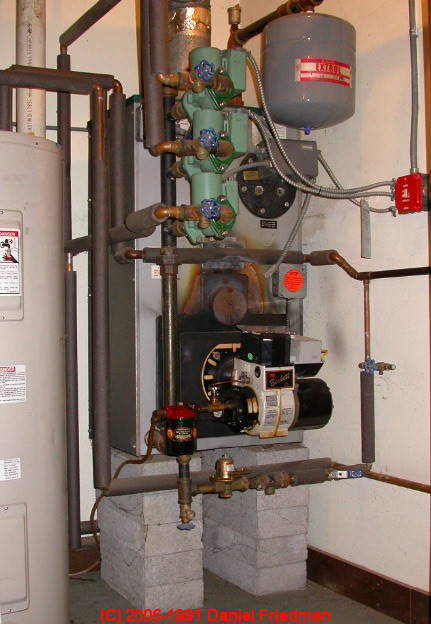
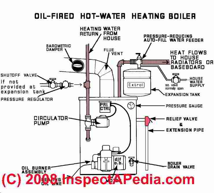
How Heating Boilers Work & are Diagnosed: Heating Boiler Inspection by Sequence of Operation
 An understanding of the sequence of steps in the operation of a heating system, from the moment that a thermostat calls for heat until the moment that the thermostat stops calling for heat can help us diagnose and fix many heating system problems.
Here we describe each step in the operation of a forced hot water heating boiler in response to a call for heat from the thermostat, and we guide you as an inspector or repair technician, by looking at each component in the boiler system.
First: How to Inspect A Heating System
Examine the accessible parts of the heating system. Let your eye travel from component to component in the sequence of operation.
Apply the inspection logic discussed
at HEATING INSPECTION CONCEPTS
at each step. Consider the implications should any component be missing, damaged, inoperative, leaky, noisy, sooty, repaired by an amateur, etc.
Think through the operating sequence as you examine each component in that order. The following are the steps in one common set-up.
While this list is lengthy and detailed, the actual visual examination may take only a few minutes.
Article Contents
- 39 STEPS in HEATING BOILER OPERATION
- CANADIAN vs US BOILER OPERATION - on demand vs continuous heating water circulation
How a Heating System Works - 39 Steps in the Operation of a Heating System
What follows is a detailed, step by step description of how a heating boiler works. We name each heating system component and what it does, in the order that heating system components operate during the heating cycle.
Items shown in [brackets] are ones which may not be present on some heating systems. We include links to technical articles that explain the operation of various heating system components and parts.
The following steps in a heating boiler operating sequence are discussed as part of a complete heating system inspection procedure for hydronic or hot water heat beginning
at HEATING BOILER INSPECTION GUIDE.
For steam heating systems, details are
Similar information is provided for warm air heating systems
- Room temperature drops
a condition sensed by one or more thermostats installed to control building temperature.
See HEAT LOSS in BUILDINGS for more details. - Room thermostat senses the temperature drop and switches on -
the thermostat is basically an "on-off" switch that calls for heat.
See THERMOSTATS - If Zone valves are installed
each is controlled by an individual thermostat; the zone valve opens
or If no zone valves are installed
each thermostat controls and turns-on one (or more) hot water circulators.
In response to the thermostat (or zone valve end switch,) the hot water circulator starts,
except in Canada where circulators may be set up to run continuously and where the thermostat directly turns on the boiler itself.
Note: the heating water circulator is usually located on cooler return-side of the distribution piping loop where the returning heating water re-enters the boiler.
This is a cooler location that gives the circulator and its motor a longer life.
See ZONE VALVES, HEATING - Boiler temperature and pressure
are indicated on the Temperature/Pressure gauge and should show an increase in the boiler water, not to exceed normal operating limits (200 deg F or less and less than 30 psi)
See GAUGES ON HEATING EQUIPMENT - Hot heating water leaves boiler
heading towards the heat-radiating devices in the occupied building space, passing by the ... - Air scoop, air separator, air purger
(not always present; this component removes air in the hot water heat piping to stop hot water heating system noise and to avoid air-bound heating baseboards or radiators)
See AIR SCOOPS SEPARATORS PURGERS - Air vent or purge valve
(mounted on top of the air scoop, a brass fitting with a Schrader valve which permits any air in the boiler or piping in this area to escape.
This component is not always present; these are often leaky or sealed off). Air purge valves, manual or automatic, may also be located at other spots on piping, baseboards, or hot water radiators themselves.
See AIR BLEEDER VALVES - Automatic water feeder
(normally the manual valve for water supply to boiler is "on", the automatic valve is closed unless the boiler pressure drops below 12-15 psi. This valve is often also a backflow preventer.)
This device might add water to the boiler as needed.
See WATER FEEDER VALVES, HYDRONIC BOILER - Expansion tank
(if waterlogged, this tank will cause hot water dumping at the relief valve). This device absorbs the initial pressure increase in the system - preventing unnecessary spillage at the pressure-relief valve.
If you don't see an expansion tank check: is there an old expansion tank in the attic?
If so, the boiler system may have no relief valve and may rely on this attic tank and an overflow pipe which itself may flow outside or to a building drain.
Modern systems, which have a smaller expansion tank right at the boiler, will also include a relief valve on (best) or close to the heating boiler itself and won't rely on a remote attic expansion tank.
See EXPANSION TANKS - Zone valve
(not always used, shorter life if installed on the "hot" supply side of the heating water loop piping)
See ZONE VALVES, HEATING - Hot water from the boiler enters the heating distribution piping
(watch for mineral salts indicating small clogged leaks) where it continues towards the occupied space in the building. - Hot water then passes through heating baseboards or radiators or wall convectors
which warm the room air by air convection and by heat radiation, and thus the...
See RADIATORS for ROOM HEAT
and AIR BLEEDER VALVES - Room thermostat
senses the heat increase as hot water from the boiler passes through and radiates heat from heating devices nearby.
When the room temperature reaches the thermostat setting, the thermostat will STOP calling for heat.
See THERMOSTATS - Hot water continues
passing through more distribution piping as it returns to heating boiler, flowing past - A Zone service drain
(drain valves installed on each heating zone piping, usually at or close to the boiler) and also past any flow balancing valves - if present - usually installed right at the zone drains to continue through the - Circulator pump
(if it's not a convection system or "gravity hot water heating system" used on older houses) and then the
See CIRCULATOR PUMPS & RELAYS - The cooler hot water finally passes back into the boiler itself
having given up much of its heat to the occupied space in the building. - Temperature in the boiler drops
as cooler water returns and lowers temperature therein. - Temperature sensor
inserted into the boiler water and connected to the heating boiler aquastat or primary control switch feels the temp drop and tells the ... - Primary control or high-limit control
that the temperature is falling inside the boiler, but nothing happens (in the U.S.) until ... - Temperature drops about 15 deg F below the HI
setting on the heating boiler Primary Control (such as a Honeywell R8182D boiler control). Then the - Primary control turns on the oil burner
(watch for drip/leak damage onto the control from above as that will damage this costly component)
(Canadian systems: thermostat may activate burner directly.)
See AQUASTAT CONTROL FUNCTIONS
or
See STACK RELAY SWITCH
or
for LP or natural gas systems, the gas valve opens
and the pilot or intermittent ignition ignites the gas burner
See GAS REGULATORS & APPLIANCE / HEATER CONTROLS
See GAS BURNER & GAS VALVE CONTROLS - The oil fired Oil Burner pumps oil
from the tank through ... (did we see the oil tank? is there an oil filter, preferably just ahead of the oil burner?)
See OIL BURNER INSPECTION
OR
the gas gas valve on gas-fueled boilers opens
to feed LP gas or natural gas to the burner
See GAS REGULATORS & APPLIANCE / HEATER CONTROLS
and GAS BURNER & GAS VALVE CONTROLS
- The copper (oil or LP gas) or black iron pipe (natural gas) fuel line
continues to send fuel towards the burner.
(Some oil burners use a 2-line piping system returns excess oil back to the tank.)
See OIL TANK PIPING & PIPING DEFECTS
or
See GAS PIPING, VALVES, CONTROLS depending on type of heating system fuel used.
Fuel continues from the supply towards the burner - Fuel flow is controlled by a safety device
If the fuel is heating oil, the oil continues past one or more Fire-o-Matic safety valves (for oil fuel) (this valve contains fusible link to shut off fuel in case of a fire) through the oil pump unit,
and through an oil filter canister,
or
if the fuel is LP gas or natural gas ,fuel is metered through the gas regulator,
See GAS REGULATORS & APPLIANCE / HEATER CONTROLS
sending ... - Fuel to the burner
If the fuel is heating oil, oil is sent at high pressure (100 to 120 psi) heating oil to burner nozzle for spray atomization into fire chamber (are the combustion chamber and chamber liner ok?)
If the fuel is LP or natural gas, fuel flows into the gas burner assembly - Fuel is ignited
If the fuel is heating oil ,the oil burner Ignition Transformer (on oil burner systems) makes high voltage which is sent as a spark to ignite oil
(tar ooze at transformer means the unit is failing, maybe from backpressure and overheating) (or on gas fired equipment, the pilot light (or electrical igniter) permits a gas valve to open and a gas burner ignites)
or
For LP or Natural Gas systems, the gas valve has opened and either the gas fuel is ignited by the standing pilot light or it is ignited by a spark generated by an igniter mechanism.
see GAS BURNER FLAME & NOISE DEFECTS
and ... - Combustion air flows in to the burner
Oil burner's air intake blower unit sends combustion air into the fire chamber...
or
the gas burner air intake or power burner blower feeds air to the gas flame.
(Is there adequate combustion air? how about when the boiler room door is closed?) - Heating fuel begins to burn
Oil (or LP or natural gas) begins to burn (watch out for rough noisy or smoky start or stumbling noisy poor shut-down of the burner, smoke, soot, odor, noise mean improper system operation)
Safety controls such as a cad cell on oil burners or a thermocouple flame sensor on gas burners assure successful combustion and will shut down the system if the burner is not operating properly.
See CAD CELL RELAY SWITCH or
See STACK RELAY SWITCH for oil burners
or
See GAS BURNER & GAS VALVE CONTROLS and
See THERMOCOUPLE REPAIR / REPLACEMENT - Hot combustion gases from burning heating fuel (oil for oil burners or LP or natural gas for gas burners)
pass through tubes (in steel boilers)
or between sections (in cast iron boilers), heating that metal,
thus sending heat back into the heating water through the heat exchanger. (Soot acts as insulation, slows heat transfer, increases temperatures in the flue, and increases heating costs -- was the boiler cleaned recently?) - Hot combustion gases are collected
at top of boiler and sent out through exhaust flue (metal pipe connecting the boiler to the chimney) ... - Combustion gas exhaust draft is regulated
Where the barometric damper (on oil burners - a draft regulator located on the flue pipe usually just above or close to the boiler OR on gas burners a draft hood located on the gas flue vent connector just above the boiler)
See DRAFT REGULATORS - barometric dampers) - for oil fired heating equipment
or a draft hood on gas-fired heating equipment
See FLUE GAS SPILL SWITCH TRIPPING & RESET assures proper and even draft; hot gases continue ... - Combustion gases are vented up the chimney
where combustion gases are vented safely outdoors
OR for direct-vent or sidewall-vented heating equipment
Combustion gases are vented outside
through a building side-wall
See CHIMNEY INSPECTION DIAGNOSIS REPAIR - Boiler temperature rises
up to the "HI" limit as the burner continues to operate.
(Thinking of the HIGH limit, this is a good time to take a look for a pressure relief valve and look for defects there: leaking, corroded, not piped to floor, reduced diameter piping.)
See RELIEF VALVE, TP VALVE, BOILER - A boiler water temperature sensor
mounted inside the boiler water monitors temperature there and informs
Primary Control when the "HI" limit is reached, causing the control to turn off the burner (is there a noisy, rough, stumbling sloppy burner shut down? If so, service is needed).
(Circulator is continuing to run all during the time that the wall thermostat calls for heat)
See AQUASTAT CONTROL FUNCTIONS or
See LIMIT CONTROL, SINGLE - The room temperature reaches the room thermostat set temperature
according to the thermostat so the ... - Thermostat senses the temperature rise and opens its switch
thus stopping or turning off the call for heat.
(Special thermostat sophistication and functions such as heat anticipators and short cycle detectors are excluded here)
See THERMOSTATS - Circulator pump stops
(except in parts of Canada or other areas where for comfort and temperature evenness, circulators are left running continuously).
See CIRCULATOR PUMPS & RELAYS - The burner is turned off
The oil Burner (or gas burner) will either stop, or even if the call for heat continues, the burner will turn OFF if HI limit is reached inside the boiler.
See AQUASTAT CONTROL FUNCTIONS
See also OIL BURNERS
and OIL BURNER NOISE SMOKE ODORS.
If a LOW WATER CUTOFF CONTROL is installed, the boiler will be shut down if water drops to an unsafe level.
Compare Operation of Heating Boilers in Canada and the U.S.
Continuous vs. Intermittent Hot Water Circulation
On a typical oil fired heating boiler in the U.S., the wall thermostat is controlling the hot water circulator, turning it on or off. It is the temperature of the water circulating through the system (sensed at the primary control on the heating boiler) that actually turns the oil burner on or off to reheat the water.
That's why the wall thermostat is not an "accelerator" and that's why, if the thermostat has been set to 60 °F., and the room temperature is at 60 °F., and we want to warm up to 68 deg.F., we just need to set the wall thermostat up to 68 deg.F.
Setting the thermostat higher than that will not warm the room faster.
On a typical oil fired heating boiler in Canada, where temperatures are cooler for more of the year, the circulator pump may be wired to run continuously all during the heating season, whenever power is turned on at the boiler. On these systems, the wall thermostat turns the oil burner on or off directly in response to room temperature.
This design tends to produce more even temperatures in the home, and it has an advantage which should be considered by anyone who owns an older home where drafts or poor insulation mean that there is a high risk of freezing heating pipes (freezing can occur in a heating distribution pipe, baseboard, or radiator when heat temperatures are set low and some corner or elbow or location of piping is exposed to very low temperatures).
If heating pipes freeze, the result is loss of heat even if the boiler and circulator try to turn on, which in turn means there is risk of burst piping, water damage, mold contamination, or other costly problems. By forcing the water in the heating system to circulate continuously, the risk of this freeze-up is greatly reduced.
...
...
Continue reading at BOILER CONTROLS & SWITCHES or select a topic from the closely-related articles below, or see the complete ARTICLE INDEX.
Or see BOILER OPERATING STEPS FAQs - questions and answers about the operating steps in hydronic or hot water heating systems & boilers, posted originally at this page.
Or see these
Recommended Articles
- BOILERS, HEATING - home
- BOILER OPERATING PROBLEMS
- DIAGNOSE & FIX HEATING PROBLEMS-BOILER
- HEATING SYSTEM INSPECTION - home - free online course in how to inspect heating systems
- HEATING INSPECTION CONCEPTS - home
- HEATING INSPECTION PROCEDURE-GENERAL
- HEATING SYSTEM INSPECTION DETAILS
- INDOOR INSPECTION of HEATING SYSTEM
- HEATING BOILER INSPECTION GUIDE
- HEATING FURNACE INSPECTION GUIDE
- FINAL BOILER/FURNACE ROOM INSPECTION CHECKS
- GAS BURNER FLAME & NOISE DEFECTS
- GAS BURNER SOOT CAUSE & CURE
- GAS BURNER PILOT LIGHT PROCEDURE
- OIL BURNER INSPECTION
- HEATING SYSTEM SAFETY INSPECTION
- SAFETY RECALLS CHIMNEYS VENTS HEATERS
- NO HEAT - BOILER
- OIL BURNER WONT RUN
- GAS BURNER FLAME & NOISE DEFECTS
- GAS BURNER SOOT CAUSE & CURE
- GAS BURNER PILOT LIGHT PROCEDURE
- HEAT WON'T TURN ON or if needed, HEAT WON'T TURN OFF
- RADIATORS for ROOM HEAT - cold radiator or baseboard diagnosis and repair
Suggested citation for this web page
BOILER OPERATING STEPS at InspectApedia.com - online encyclopedia of building & environmental inspection, testing, diagnosis, repair, & problem prevention advice.
Or see this
INDEX to RELATED ARTICLES: ARTICLE INDEX to HEATING BOILERS
Or use the SEARCH BOX found below to Ask a Question or Search InspectApedia
Ask a Question or Search InspectApedia
Try the search box just below, or if you prefer, post a question or comment in the Comments box below and we will respond promptly.
Search the InspectApedia website
Note: appearance of your Comment below may be delayed: if your comment contains an image, photograph, web link, or text that looks to the software as if it might be a web link, your posting will appear after it has been approved by a moderator. Apologies for the delay.
Only one image can be added per comment but you can post as many comments, and therefore images, as you like.
You will not receive a notification when a response to your question has been posted.
Please bookmark this page to make it easy for you to check back for our response.
IF above you see "Comment Form is loading comments..." then COMMENT BOX - countable.ca / bawkbox.com IS NOT WORKING.
In any case you are welcome to send an email directly to us at InspectApedia.com at editor@inspectApedia.com
We'll reply to you directly. Please help us help you by noting, in your email, the URL of the InspectApedia page where you wanted to comment.
Citations & References
In addition to any citations in the article above, a full list is available on request.
- Domestic and Commercial Oil Burners, Charles H. Burkhardt, McGraw Hill Book Company, New York 3rd Ed 1969.
- National Fuel Gas Code (Z223.1) $16.00 and National Fuel Gas Code Handbook (Z223.2) $47.00 American Gas Association (A.G.A.), 1515 Wilson Boulevard, Arlington, VA 22209 also available from National Fire Protection Association, Batterymarch Park, Quincy, MA 02269. Fundamentals of Gas Appliance Venting and Ventilation, 1985, American Gas Association Laboratories, Engineering Services Department. American Gas Association, 1515 Wilson Boulevard, Arlington, VA 22209. Catalog #XHO585. Reprinted 1989.
- The Steam Book, 1984, Training and Education Department, Fluid Handling Division, ITT [probably out of print, possibly available from several home inspection supply companies] Fuel Oil and Oil Heat Magazine, October 1990, offers an update,
- The Lost Art of Steam Heating, Dan Holohan, 516-579-3046 FAX
- Principles of Steam Heating, Dan Holohan, technical editor of Fuel Oil and Oil Heat magazine, 389 Passaic Ave., Fairfield, NJ 07004 ($12.+1.25 postage/handling).
- "Residential Steam Heating Systems", Instructional Technologies Institute, Inc., 145 "D" Grassy Plain St., Bethel, CT 06801 800/227-1663 [home inspection training material] 1987
- "Residential Hydronic (circulating hot water) Heating Systems", Instructional Technologies Institute, Inc., 145 "D" Grassy Plain St., Bethel, CT 06801 800/227-1663 [home inspection training material] 1987
- "Warm Air Heating Systems". Instructional Technologies Institute, Inc., 145 "D" Grassy Plain St., Bethel, CT 06801 800/227-1663 [home inspection training material] 1987
- Heating, Ventilating, and Air Conditioning Volume I, Heating Fundamentals,
- Boilers, Boiler Conversions, James E. Brumbaugh, ISBN 0-672-23389-4 (v. 1) Volume II, Oil, Gas, and Coal Burners, Controls, Ducts, Piping, Valves, James E. Brumbaugh, ISBN 0-672-23390-7 (v. 2) Volume III, Radiant Heating, Water Heaters, Ventilation, Air Conditioning, Heat Pumps, Air Cleaners, James E. Brumbaugh, ISBN 0-672-23383-5 (v. 3) or ISBN 0-672-23380-0 (set) Special Sales Director, Macmillan Publishing Co., 866 Third Ave., New York, NY 10022. Macmillan Publishing Co., NY
- Installation Guide #200 for Residential Hydronic Heating Systems, The Hydronics Institute, 35 Russo Place, Berkeley Heights, NJ 07922
- The ABC's of Retention Head Oil Burners, National Association of Oil Heat Service Managers, TM 115, National Old Timers' Association of the Energy Industry, PO Box 168, Mineola, NY 11501. (Excellent tips on spotting problems on oil-fired heating equipment. Booklet.)
- In addition to citations & references found in this article, see the research citations given at the end of the related articles found at our suggested
CONTINUE READING or RECOMMENDED ARTICLES.
- Carson, Dunlop & Associates Ltd., 120 Carlton Street Suite 407, Toronto ON M5A 4K2. Tel: (416) 964-9415 1-800-268-7070 Email: info@carsondunlop.com. Alan Carson is a past president of ASHI, the American Society of Home Inspectors.
Thanks to Alan Carson and Bob Dunlop, for permission for InspectAPedia to use text excerpts from The HOME REFERENCE BOOK - the Encyclopedia of Homes and to use illustrations from The ILLUSTRATED HOME .
Carson Dunlop Associates provides extensive home inspection education and report writing material. In gratitude we provide links to tsome Carson Dunlop Associates products and services.
 |
HOME | ABOUT | ASK a QUESTION | CONTACT | CONTENT USE POLICY | DESCRIPTION | POLICIES | PRIVACY | |
| © 2026 - 1985 Publisher InspectApedia.com - Daniel Friedman | |||||||||