
InspectAPedia®FREE Encyclopedia of Building & Environmental Construction, Diagnosis, Maintenance & Repair |
Question? Just ask us! InspectAPedia
|
 Wire the Fan & Limit Controls on Furnaces
A-1, Camstat, Cemco, Columbus, Firestat, Goodman, Honeywell, Supco, White Rodgers & Other Fan Limit Controls
- POST a QUESTION or COMMENT about how to hook up or wire the furnace blower fan limit control switch
Fan limit switch wiring details:
This article describes in detail the installation & wiring of furnace combination controls, also commonly called the "fan limit switch" on warm air heating systems.
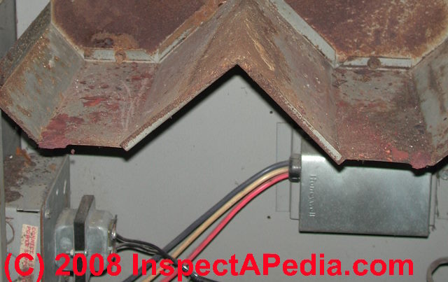
The photo at the top of this page shows all of the controls and wiring terminals in a Honeywell combination fan and limit control installed horizontally on a gas furnace.
InspectAPedia tolerates no conflicts of interest. We have no relationship with advertisers, products, or services discussed at this website.
- Daniel Friedman, Publisher/Editor/Author - See WHO ARE WE?
Install and Wire the Furnace Combination Control Fan Limit Switch
Here we include both old and current guides to Installing & Wiring Fan Limit Switches on Warm Air Furnace Heating Systems for all major brands of fan limit control switches used on heating furnaces and other fan systems.
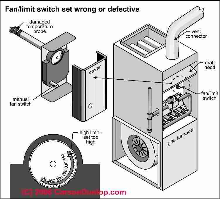
The sketch at above/left, courtesy of Carson Dunlop Associates, shows an improper (too high) upper limit setting - this is an unsafe fan-limit switch setup which is likely to allow the furnace to overheat, risking heat exchanger damage and dangerous carbon monoxide leaks.
Article Contents
- HOW TO INSTALL & WIRE FAN LIMIT SWITCHES
- FURNACE COMBINATION CONTROL OPERATING TEMPERATURE RANGE & LIMITS
- WHERE TO MOUNT THE FURNACE FAN-LIMIT CONTROL - where is the fan limit switch located?
- TEST & CHECKOUT PROCEDURE for FAN LIMIT SWITCH CONTROL
- A-1 FAN LIMIT SWITCH
- CAMSTAT & SUPCO LIMIT CONTROL WIRING GUIDES & MANUALS
- CEMCO FAN LIMIT CONTROL WIRING GUIDES & MANUALS
- COLUMBUS ELECTRIC FAN LIMIT SWITCH
- DELCO LIMIT CONTROL SWITCH
- EMERSON Therm-O-Disc PRODUCT INFORMATION [PDF] (2020) - Emerson Electric Co., St. Louis, MO, USA, Website: emerson.com
Excerpt: Bimetal disc thermostats are thermally actuated switches. When the bimetal disc is exposed to its predetermined calibration temperature, it snaps and either opens or closes a set of contacts. This breaks or completes the electrical circuit that has been applied to the thermostat. - FIRESTAT FAN LIMIT CONTROLS - Senasys
- GOODMAN FURNACE CONTROLS
- HONEYWELL FAN LIMIT CONTROL WIRING GUIDES & MANUALS
- HONEYWELL COMBINATION FURNACE CONTROL TYPE L4064 WIRING HOOKUP
- HONEYWELL L4064B COMBINATION FURNACE CONTROL WIRING
- HONEYWELL L4064B LIMIT WIRING WHEN CONTROLLING LOW VOLTAGE - also see the 4064T
- HONEYWELL L4064T LIMIT CONTRL WIRING
- HONEYWELL L4068 & 4069 FAN & FURNACE CONTROLLER WIRING
- NORDYNE FAN LIMIT CONTROL SWITCH - Nordyne Therm O Disc
- WHITE RODGERS FAN LIMIT CONTROL WIRING GUIDES & MANUALS
- WIRING LIMIT SWITCHES: GENERAL ADVICE - polarity & other issues at the fan limit control
...
Furnace Combination Control Operating Temperature Range & Limits
The switch portion of this Honeywell Fan Limit control can tolerate 190 °F. and the sensing element can handle up to 350 °F.
The control can handle 120V and 240V devices and can also be wired to control low-voltage devices.
The electrical wiring used must also be rated for suitable temperature exposure (Honeywell advises wiring rated for 167°F).
At 120V the control can switch fan motor loads at 14 Amps full load (84 Amps locked rotor load), and the limit switch (presumably an oil or gas burner) can handle up to 8 Amps full load (48 Amps locked rotor load).
When controlling 240V devices the fan or blower control can handle up to 7 Amps full load (42 Amps LRA) and the limit switch can handle 4 Amps full load (24A LRA).
...
Where to mount the furnace Fan-Limit Control
This furnace combination control is mounted on the furnace in a location where the bimetallic spring/probe (shown above in this article) will protrude into the warm air plenum to sense furnace air temperatures there.
Each furnace manufacturer will provide instructions of where, on their system, the air temperature should be monitored for control purposes.
The reason the control manufacturer warns that the control tip should not touch any internal surfaces of the furnace is that doing so can cause improper reading of furnace air temperatures or could damage the control or prevent free movement of the bimetallic spring in response to temperature changes.
Of course if you are replacing an old control that has failed, just mount the control in the same location that held the prior unit.
When replacing an old furnace limit control, make sure that the new control has a sensing tip of the same length as the unit being replaced. Otherwise the new control may not work safely.
The manufacturer provides details for surface mounting, rigid-bracket mounting, or swivel-mounting of the control. Which of these methods you choose depends on what mounting is needed to place the sensor probe in the proper location in the air plenum.
What if you Cannot Find the Fan Limit Switch on your Furnace?
Our reader asked:
I have a Beckett burner (AFG) forced air system that is about 20 years old. It works well.
I just purchased a Honeywell primary R7284U to replace, if needed, the original R8184G just in case (it's 20 years old, too).
The old primary has 3 wires and the new one is more complicated.
My question: I cannot find the fan limit switch in my furnace.
I've found two sensors at two places in the plenum but no fan limit switch.
I looked in the lower and upper compartments and in front of the blower and found a Honeywell circuit board that a red wire from the sensors is plugged into, but no switch as shown in all the diagrams I have seen online.
I need to wire the limit into the new primary when I eventually install it. I could use some help. A lot of it. Thank you very much. Richard. On 2020-11-23 by Richard Garcia
by (mod) - look for a snap disc control
Richard
It's possible that the R7284U that you bought is not suitable for your furnace - if yours uses a different type of limit control switch.Some forced-warm air furnaces use a snap switch or other control to manage the fan on-off-high limits, so you may not see the traditional Honeywell fan limit controller but you might see smaller, perhaps brown or black phenolic plastic "boxes" maybe just a couple of inches across.
There ought to be one or more fan limit controls that will be mounted on or in the warm air supply plenum as that's where they have to sense temperature.
So you may be able to follow wires back from the blower motor to the plenum.
Tell me the furnace brand and model and if you don't already have the IO Manual that would show those details we may be able to provide one as we've got a zillion heater manuals as PDFs for readers to download.At our home page for this topic - FAN LIMIT SWITCH GUIDE - you'll see that some furnaces use a snap disc to control the temperature limit rather than the much larger boxy fan limit switch.
by Richard Garcia
@danjoefriedman
Thanks for the reply.When you mentioned the manual it reminded me that the previous owner of my house (I've been living here one year) left her documents and I found the Carrier booklet for my model 58CMA oil furnace.
Apparently I have an electronic fan timer (Honeywell circuit board ST9103) and the limit controls, two of them, are shown on the circuit diagram.
Now I have to figure out the wiring for my new primary, but at least I'm not driving myself crazy trying to find a analog limit switch. Thanks again for your reply.
RichardReply by (mod) -
Thank you for the update that will perhaps help other readers as well. Keep me posted.
Can I move the furnace fan limit control switch?
Have an old horizontal furnace that works fine but concerned that the fan/limit control could fail.
The existing control's sensors are crammed in the side in that the plenums are vertical.
Any reason why I couldn't mount a new control on top of the furnace and have the sensors run between the mid plenum plates. On 2020-03-29 by John
by (mod) - NO
John
Watch out: It's really important that the fan limit control sensor is in the very and exact spot specified and designed by the manufacturer.The danger in moving the sensor / control is that if it doesn't sense plenum temperature as designed the system is unsafe, potentially overheating, cracking the heat exchanger, and killing the building occupants with carbon monoxide.
...
Wiring the Furnace Combination Fan & Limit Control using the Honeywell L4064B as an Example
 The following example of wiring a fan limit control switch is based on advice from the Honeywell Tradeline L4064B. Check the test specifications provided by the manufacturer of your particular control.
This control can be wired to serve as a safety LIMIT switch on a furnace by wiring just the limit terminals on the control. When the device is used both to control a furnace fan on-and off as well as serve as a LIMIT switch, then all four terminals are used.
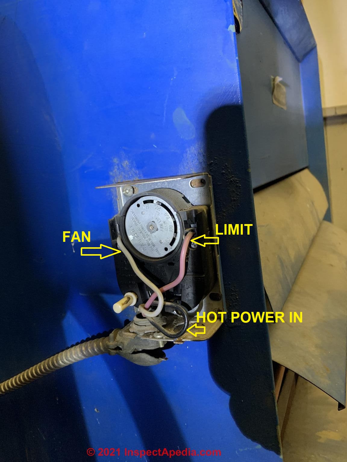
Fan control wiring: As Honeywell's illustration shows, the two fan terminals are on the upper and lower left side of the control.
Line voltage is wired at the bottom left push-in terminal.
Load voltage (to the fan) is wired at the upper left push-in terminal.
Limit control wiring: As the illustration shows, the two LIMIT terminals are on the upper and lower right side of the L4064B control.
The Line (power in) wire is connected to the lower right push-in terminal, and the Load (wire to oil or gas burner) is wired to the upper right push-in terminal.
The wiring diagrams shown in more detail below are typical for wiring the furnace combination control on heating systems.
Remember that all electrical wiring of furnace controls (or any other electrical devices) must comply with national and local electrical codes as well as the specifications of the control manufacturer and the furnace manufacturer.
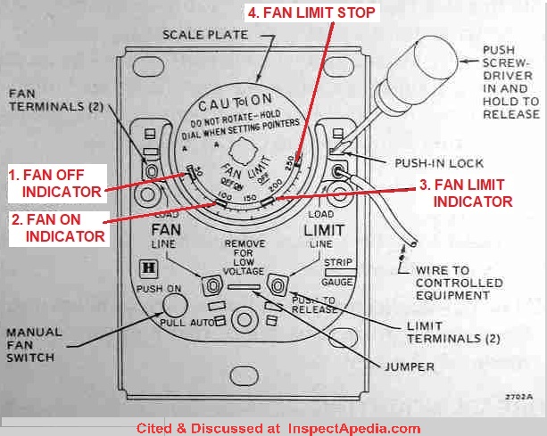
Wires are connected to the control using push-in terminals. A wire strip gauge is provided on the left side of many versions of this control.
The control used for our photos came with additional push-in terminals (Part # 137813) that can be used to convert the push-in wiring connectors to screw-terminal connectors.
This is a great idea if you expect to be changing wiring from time to time. (Dr. Jess Aronstein's research has demonstrated that repeated-use or re-use of push-in type terminals on electrical receptacles does not provide a very reliable connection. This may be true for this control as well.)
Fan Limit Switch Installation Manuals 1970 to Present, for A1, Camstat, Cemco, Goodman, Honeywell & White Rodgers
...
A-1 Components Fan Limit Control
- A-1 Components, BC-7070-A//M "ON/OFF" TIME DELAY RELAY FAN LIMIT CONTROLLER MANUAL [PDF], A-1 Components, Henry Technologies, Inc., 701 S. Main St., Chatham IL 62629, USA Tel: 217-483-2406, Websites: www.henrytech.com or www.a-1components.com
Product description: This fan limit switch is also referred to as a Cam-Stat control or a time-delay relay because it allows setting a timed delay in fan-on or fan-off cycles.
This Time Delay Relay replaces the following: BC-7070-A/M, AZ2100-1A-24DEF, 4033500, 026-32588-014, L44-495
Compatible with the following units: AGM04008C AGM04012C AGM06008C AGM06012C AGM06016C AGM08008C AGM08012C AGM08016C AGM08020C AGM10012C AGM10016C AGM10020C AGM12016C AGM12020C AGM14016C AGM14020C P1BHD12L03201A P1BHD12L04801A P1BHD12N03201A P1BHD12N04801A P1BHD16L06401A P1BHD16L08001A P1BHD16N06401A P1BHD16N08001A P1BHD20L08001A P1BHD20L09601A P1BHD20N08001A P1BHD20N09601A
Watch out: most suppliers warn that Gas valves, circuit boards, and replacement parts in general should be installed by a licensed professional. Failure to read and follow all instructions carefully before installing or operating this control could cause injury, fire, damage, death. - A-1 COMPONENTS BC-7070-A/M BLOWER CONTROLLER [PDF]
- Contact A-1 Components Corporation
625 West 18th Street
Hialeah FL 33010
USA Tel. 1-800-759-2872
Fax. 1-800-759-9299
Website: www.a-1components.com
A-1 Components, founded as Wagner Tool Co. in 1946, provides HVACR components in the U.S. including the following brand names:
Cam-Stat® RF (Z-QWave), Magni-Chek™, Cam-Stat, Line Backer™, Allin Liquid Eye™,a A1, A2, & A3 Line Tap Valves, and other brands names used by HVACR technicians.
...
Camstat & Supco Fan Limit Control Wiring & Manuals
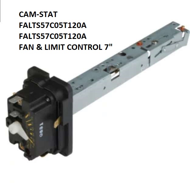
Cam-stat FAL7C-05TD-120-A Fan & LImit control (shown above)
- CAM-STAT (SUPCO) FAL3C05TD120A FAL FAN & LIMIT CONTROL MANUAL [PDF] retrieved 2018/03/05, original source: Supco, http://www.supco.com/web/supco_live/products/FAL3C05TD120A.html
- CAMSTAT FAN LIMIT SWITCH CamStat FALTS57C05T120A MANUAL [PDF] The Cam-Stat F566 & F567 include a 24VAC 0.8A "heat assist" circuit that turns blower on using a timed delay independent of the actual plenum temperature. This series includes Cam-Stat F562, F563, F564, F566, F567. retrieved 2018/03/05, original source: Supco. Op. Cit.
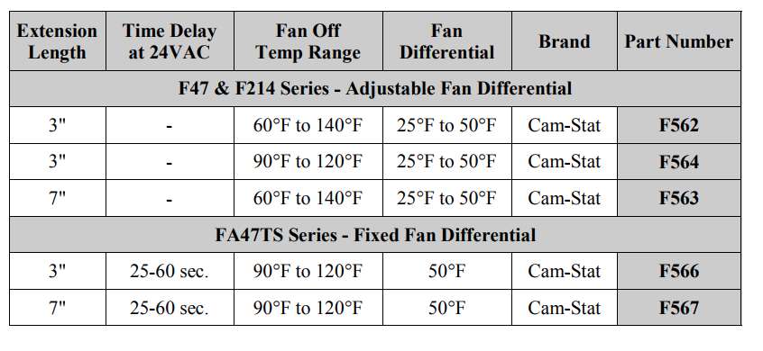
Cam-Stat is a division of Supco. The Cam-Stat fan limit switch provides a dial-adjustable FAN OFF temperature ranging from 90°F to 120°F, a FAN LIMIT temperature ranging from 150°F to 250F, and typically a fixed differential of 30°F.
- CAMSTAT L593BA L59 LIMIT CONTROL (Supco) MANUAL [PDF], retrieved 2018/03/05, original source: Supco, http://www.supco.com/web/supco_live/products/L593BA.html
- OEM HEATING CONTROL REPLACEMENTS FOR CAMSTAT CONTROLS: [PDF] L59 Series Limit, FALT Series Fan Controls, F47 & F214 Fan Control, F47TS Fan Control, S106 Time Delay Relay, PR Pilot Igniters, BC6060 F7070 Blower Control, CIVA5 Brown Out Delay Timer, AFC01T110204 Attic Fan Control, from Supco Sealed Parts Co., Inc., Allenwood NJ, Tel:L 800-333-9125, Website: www.supco.com
...
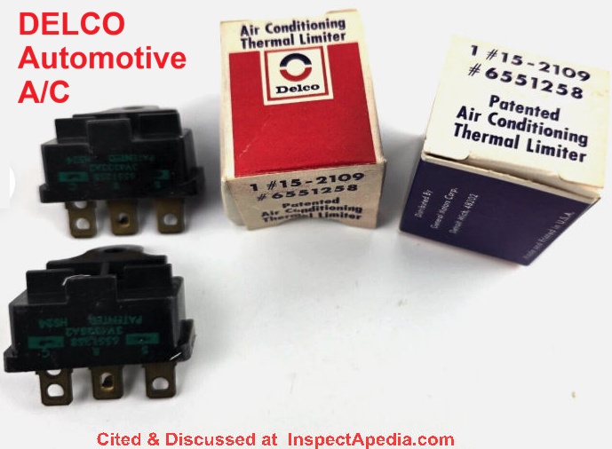
Delco / GM Thermal Limiter Control
Shown here, the Delco / General Motors 1502109 #6551258 Air Conditioning Thermal Limiter, a widely-used thermal limit control in automotive air conditioning systems. You won't find this switch in building air handlers for furnaces or air conditioners, but we list it here because of its frequent appearance when searching for and identifying temperature limit control switches.
...
Supco Fan Limit Control Switches
- SUPCO CAMSTAT FURNACE FAN LIMIT CONTROL SWITCHES - wiring diagram [PDF]
- SUPCO CAMSTAT FURNACE FAN LIMIT CONTROL SWITCHES - parts ordering information [PDF]
- SUPCO FURNACE LIMIT SWITCH SELECTION CHART [PDF] retrieved 2018/02/08 original source: https://www.grainger.com/ec/pdf/2FBW9_2.pdf
...
Senasys Firestat Duct Limit Controller - fire safety switch
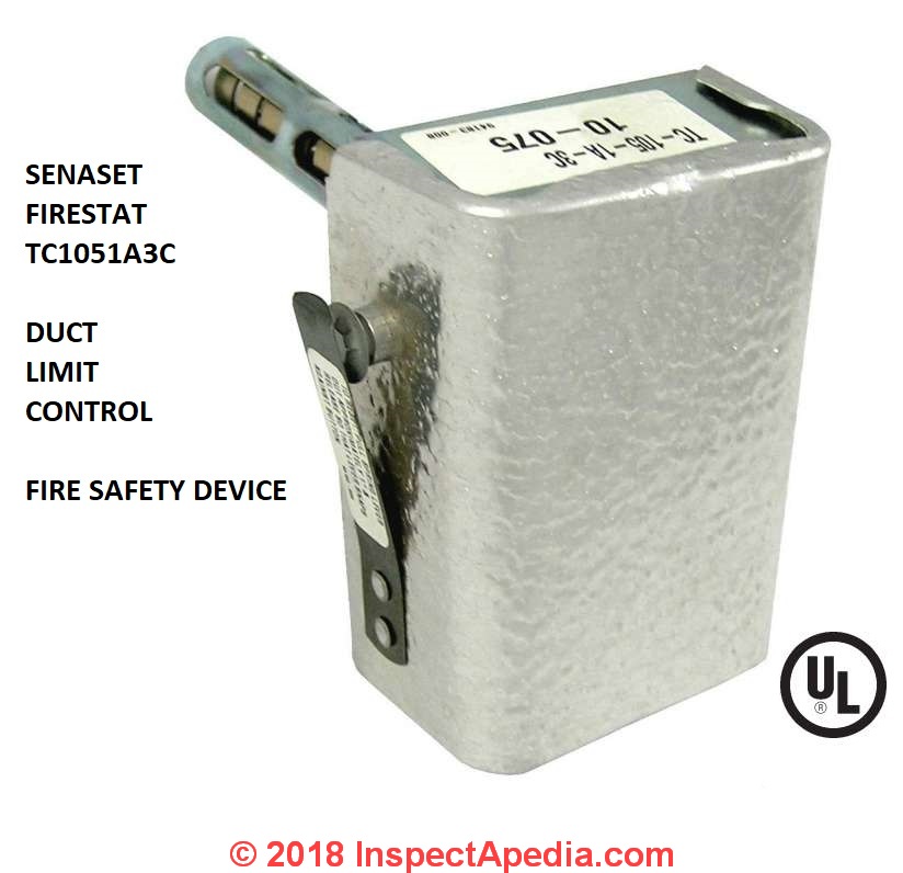
Shown above: the Senasys Firestat HVAC duct fan limit controller, a fire safety device that turns off the HVAC blower in event of a fire.
- Senasys Products Used in HVAC [Website] Senasys, 1435 International Drive Eau Claire, WI 54701 U.S.A. +1 (715) 831-6353 info@senasys.com
...
CEMCO Limit Control Wiring Guides & Manuals
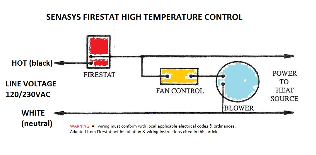
- CEMCO SENASYS TC-Series FIRESTAT DUCT FAN LIMIT CONTROL WIRING DIAGRAM, [PDF] Columbus Electric, SenaSys, 704 Bartlett Avenue Altoona, WI 54720, USA Tel: 715-831-6353 Email: info@senasys.com. retrieved 2018/03/05, original source: http://firestat.net/wp-content/uploads/2017/05/TC-Wiring-Diagram.pdf [shown below]
Website Excerpts:
The Columbus Electric TC Series FIRESTAT is a push-button manual reset limit control designed expressly for fire prevention in warm air ducts.
It may be used with gas, oil, or electric forced warm air heating systems. One or more FIRESTATS should be installed in duct work at critical temperature locations such as down-stream from electric heaters, points where duct work is in close proximity to flammable materials, etc.
FIRESTATS may be used in low voltage or line voltage circuits and are usually wired to open [the] circuit to both heat source and blower when duct air temperature exceeds the temperature setting [of the FIRESTAT safety device].
If more than one FIRESTAT is connected to control a single heat source, the FIRESTATS must be connected in series. A typical [FIRESTAT] wiring diagram is shown below [edited for clarity by InspectApedia.com].
- CEMCO SENASYS FIRESTAT DUCT FAN LIMIT CONTROL SPECIFICATIONS [PDF] retrieved 2018/03/05, original source: http://senasys.com/products/firestat-limit-switch
Website Excerpts:
The TC Duct Limit Controls contain a Helix Bi-Metal that senses rapid increases in duct temperature such as fire. The Bi-Metal causes the normally closed contacts to open and turn off the power
Available in either adjustable [TC-100, TC-105, TC-108] or fixed temperature [TC-205] models. These firestat limit switches are installed in air ducts to shut down heating, air conditioning and ventilation equipment when air temperature in duct exceeds a pre-set limit.
The Duct High Temperature Limits feature a helix bimetal element that senses rapid increases in duct temperature, such as those caused by fire. The high temperature limit then operates an SPST switch that opens with a rise in temperature.
A manual reset button reactivates the temperature limit after the high-temperature condition has cleared. These duct high temperature limits are indispensable in specialized HVAC applications and Building Automation Systems.
...
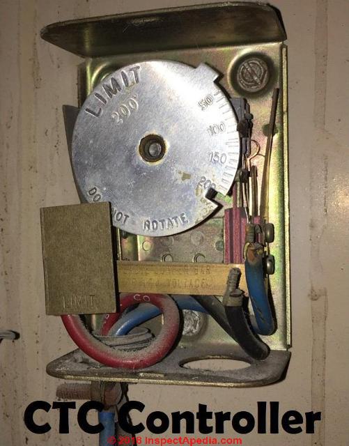
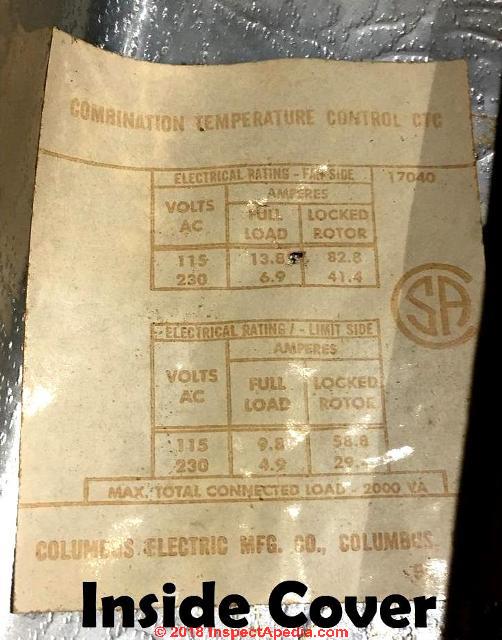
Columbus Electric Fan Limit Control
- COLUMBUS ELECTRIC COMBINATION TEMPERATURE CONTROL [citation and manuals wanted]. (Shown above)
Columbus Electric, originally in Columbus Ohio, U.S. is a division of TPI Corporation. The company produced HVAC controls including fan limit controls such as the unit shown here, line voltage electric heat wall thermostats, and other controls and equipment.
Contact: Columbus Electric Division of TPI, PO Box 4973, Johnson City, TN 37602 USA, Tel 800-251-7828, Fax 423-477-0545
or
TPI Corporation, Website: www.tpicorp.com, Tell: 1-800-682-3398. The company's current product lines include Markel Products, Raywall, and Fostoria and a very large range of HVAC equipment and controls.
Columbus Temperature Control, Columbus Temperature Control, 1053 East 5th Avenue Columbus OH 43201 USA Tel: 614-294-6216 markets under Distech Controls and currently specializes in networked, electronic interfaces and controls for security, HVAC, lighting, access control, energy menagement systems.
Thanks to reader Larry C. for the Columbus Electric Combination Temperature Controller photographs, 2018/07/25. He wrote that this control was used on a dual-zone heating and air conditioning system.
See LINE VOLTAGE THERMOSTATS for installation guides for other thermostats produced by Colubus Electric / TPI.
Other Columbus Electric HVAC Controls
- COLUMBUS ELECTRIC AIRFLOW SENSOR SWITCH [PDF] HVAC duct airflow control (At Grainger's Website)
Excerpt: This airflow switch may be Used to sense duct static Pressure or to prove blower is Running and performs as an Interlock to assure proper Air movement when equipment Is on and running. The device is gravity sensitive and Must be installed in a vertical Position. - Columbus Electric Line Voltage 8051-Series Thermostat Manual [PDF] (At TPI Corporation's Website ) - local backup copy saved as Columbus-Electric-Thermostat-Manual.pdf
...
Goodman Furnace Controls
- Goodman Manufacturing Company, L.P., 2550 North Loop West, Suite 400, Houston, TX 77092, www.goodmanmfg.com
- See GOODMAN HVAC MANUALS & ERROR CODES for access to Goodman's heating and air conditioning equipment manuals and installation instructions including
Goodman Mfg Gas Fired Central Furnaces INSTALLATION & OPERATING INSTRUCTIONS GAS FIRED WARM AIR FURNACE AMV8 at http://www.goodmanmfg.com
...
Honeywell Fan Limit Control Wiring & Manuals
Honeywell L4029 Series Limit Controls
- HONEYWELL L4029 RESET LIMIT CONTROL, [PDF] (1988) also available at www.honeywell.com
- HONEYWELL L4029E HIGH LIMIT CONTROLLER IO MANUAL [PDF] L4029E Reset Limit Control
The L4029E Reset Limit Control opens a line or low voltage circuit if the air temperature reaches a critical level at a controller location. The primary usage of the L4029E is as a fire thermostat in the duct work of air conditioning and ventilating systems.
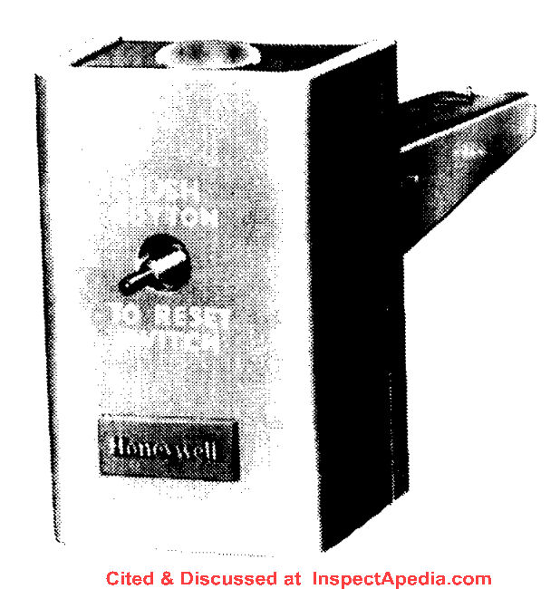
If the circulated air reaches a temperature indicative of a fire, the limit control shuts off the fan, preventing the fan from contributing to the spread of fire. It is also suitable for use with any warm air furnace to provide positive lockout of the burner in the event of a fan failure. - Honeywell L4029 RESET LIMIT CONTROL, also available at www.honeywell.com [older instructions]
Honeywell L4046 Series Fan Limit Controls
- HONEYWELL L4046B / L4064 FAN LIMIT SWITCH INSTALLATION & WIRING
- HONEYWELL L4046B UNIVERSAL-FAN-LIMIT-CONTROL-MANUAL [PDF]
Honeywell L4064 Series Fan Limit Controls
- HONEYWELL L4064A-F,J,R,T,W,Y FAN AND LIMIT CONTROLLERS INSTRUCTIONS [PDF] (2010) - current instructions
- HONEYWELL L4064B, L4064 R UNIVERSAL COMBINATION FAN & LIMIT CONTROLLERS MANUAL [PDF] (2013)
- HONEYWELL L4064 FAN LIMIT CONTROLINSTALLATION INSTRUCTIONS [PDF file]
- HONEYWELL L4064A-F,J,R,T,W,Y FAN AND LIMIT CONTROLLERS INSTRUCTIONS [PDF] (1985)
- HONEYWELL L4064 FAN_LIMIT SWITCH [PDF]
- HONEYWELL L4064B MANUAL [PDF]
- HONEYWELL L4064 FAN LIMIT CONTROL INSTALLATION INSTRUCTIONS [PDF]
- HONEYWELL L4064B FAN LIMIT CONTROL SETTINGS
- HONEYWELL L4064B, L4064R UNIVERSAL COMBINATION FAN & LIMIT CONTROLLER INSTALLATION MANUAL [PDF] (2017) 69-00115-11 Honeywell
1985 Douglas Drive North
Golden Valley, MN 55422-3992
customer.honeywell.com
This L4064B, L4064R limit controller is a universal replacement for older furnace fan limit controllers. Here is the difference between the L4064B and L4064R, excerpting from the document above:
These combination warm air fan and limit controllers are suitable for various types of forced air heating systems. The controllers have 2 switches; one which opens the limit circuit if the plenum temperature exceeds the preset safety limit; it resets automatically. The other switch turns the fan on and off.
The fan is turned on and off according to plenum temperature.
The L4064R has a special high temperature range suitable for gravity heating systems.
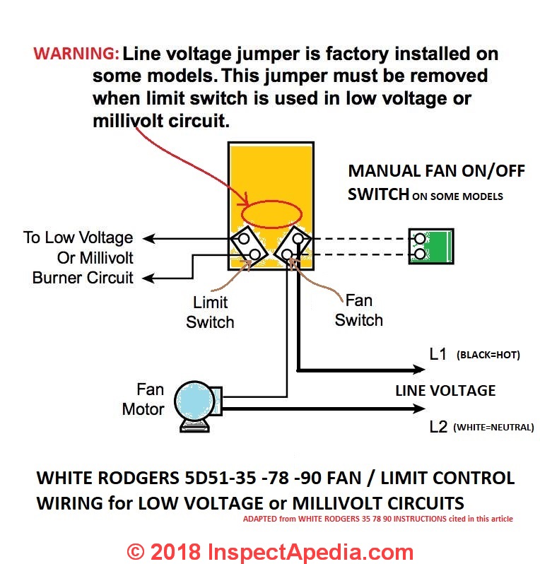
All models may be used as limit controllers by wiring only the limit side. Limit contacts are suitable for both line voltage and low voltage. For low voltage applications, the brass jumper must be removed.
...
Follow furnace or burner manufacturer’s instructions, if available.
Maximum element temperature is:
L4064B—350 ºF (177 ºC).
L4064R—250 ºF (121 ºC) above limit setting.
Maximum switch temperature is: L4064B,R—190 ºF (88 ºC). - HONEYWELL L4064B-L4064R Fan Limit Control INSTALLATION INSTRUCTIONS-2013 [PDF] (2013) Form No. 69-0115-08
- HONEYWELL SUPER TRADELINE L4064B UNIVERSAL FAN & LIMIT CONTROLLER INSTALLATION MANUAL [PDF] (2006) 69-0117-3 OBSOLETE but useful if you have a control from this period; Product Data, installation & setting instructions, retrieved 2017/04/23, original source: https://customer.honeywell.com/resources/techlit/TechLitDocuments/69-0000s/69-0117.pdf
- HONEYWELL TRADELINE L4064B, W COMBINATION FAN & LIMIT CONTROLER INSTALLATION MANUAL [PDF] (1984) Rev. 12-84, Form NO. 69-0116-2 OBSOLETE but useful if you have this older control
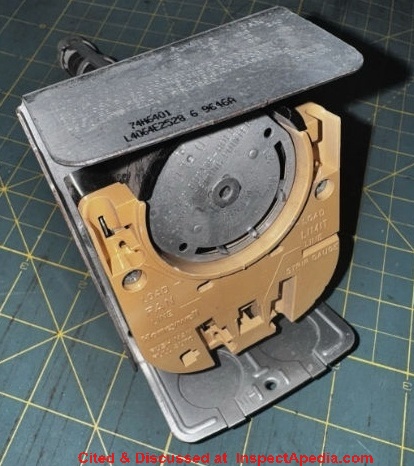
Shown above: a Honeywell L4064E2528 fan and limit control with a 5-inch probe, often used on the Lennox 74H6401 furnace. Still available for about $130 U.S. Notice that this fan limit switch does not include a manual FAN-ON/AUTO switch.
- HONEYWELL L4064A-F, J,R,T,W,Y FAN LIMIT CONTROLLER INSTALLATION - ALL MODELS [PDF] (1985) Rev. 1-85, Form No. 68-0024-1 OBSOLETE but useful if you have this older control
L4064 A-F, J, R turn the blower fan on/off based on plenum temperature
L4064 T, W, Y have a 20-90 second delay before turning the fan ON after a thermostat call for heat (avoiding blowing cool air on occupants)
L4064 B,D,F,R,W have also a manual FAN-ON switch to keep the an on continuously
L4064 J,R had a special high-temperature range for older furnaces burning gas, oil, coal, wood
The control was also sold as a SUPER TRADLINE model that included a variety of mounting adapters and protective covers. - HONEYWELL L4064A-F,J,R,T FAN & LIMIT CONTROLLER INSTALLATION & WIRING [PDF] (1981) Rev. 4-81 Form No. 60-2258-2 special thanks to reader Haydn Chambers for providing this document, 2018/03/04
- HONEYWELL L4064T INSTRUCTIONS [PDF] (ca 1970) wiring diagram shown below thanks to reader Haydn Chambers, used an extra set of spade terminals in the center of the control - these were connected to low-voltage terminals that provided a fan-timer heater function such as shown in the illustration that includes a low-voltage (24VAC) gas valve and thermostat.
- HONEYWELL L4064B UNIVERSAL COMBINATION FAN & LIMIT CONTROLLERS, [PDF] Honeywell Corporation, Minneapolis, MN 55408. Honeywell has sales offices in all principal cities in the world and has manufacturing facilities in Australia, Canada, Finland, France, Germany, Japan, Mexico, Netherlands, Spain, Taiwan, United Kingdom, U.S.A. Honeywell Form Number 60-0450 7-75, residential division. Honeywell's latest product data for this type of control can be found in English at http://customer.honeywell.com/Techlit/Pdf/69-0000s/69-0117.pdf
- HONEYWELL L4064 FAN LIMIT CONTROL INSTALLATION INSTRUCTIONS [PDF file]
- "Quick Installation Guide, RTH2300 5+2 Programmable Thermostat", Honeywell Corporation, September 2009.

Above: Honeywell L4046T Wiring diagram.
Below: Honeywell L4068A-C-E-F Wiring Diagrams from the manual given just below.
...
Honeywell L4064B Limit Wiring When Controlling Line Voltage (120V or 240V) - Control Installation Notes
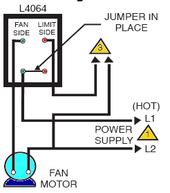
In most applications in the U.S. and Canada the Honeywell L4064B combination control is used to switch on and off 115V-120V or 240V fans and heating burners, or on some gas equipment, the burner controls (the LIMIT switch function) operates at low voltage.
The pull-out or break-off tab discussed at HONEYWELL L4064B LIMIT WIRING WHEN CONTROLLING LOW VOLTAGE is left in place for line voltage applications.
The left-illustration shows normal wiring for this set-up. The fan or furnace blower motor is controlled by the two left connections (green dots); the furnace limit switch which will turnoff the burner if the temperature limit is reached is controlled by the two right connections (red dots).
Here the furnace limit switch is controlling a line-voltage device. The colored triangles refer to notes given below.
The illustration below shows the wiring for controlling line voltage when the jumper or pull out tab has been removed.
You can see that in effect the installer in effect is replacing the missing jumper by installing a connection to both terminals on either side of the contacts where the jumper was removed.
This important detail permits this control to be used to control line voltage (120V) devices even if the jumper has been removed or the paper pull-out tab on older controls has been lost.
Wiring Notes for the Combination Furnace Control L4064B:
- Be sure to add a power disconnect switch and overload (fuse or circuit breaker) protection on this circuit. Note that the jumper or paper tab has been left in place.
- Wires to control low-voltage equipment - in this case the jumper has been removed.
Additional installation details for this control in thelatest form are available from Honeywell (cited below).
...
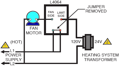
Honeywell L4064B Limit Wiring When Controlling Low Voltage - Control wiring Details
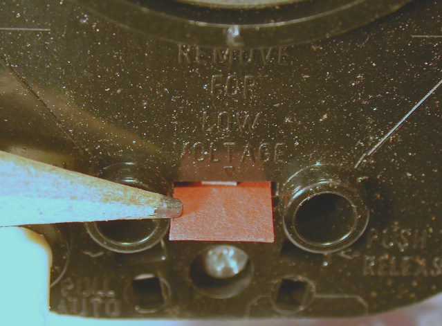 Pull the tab at the bottom of the Limit Control for use with low voltage equipment
To prepare the L4064B furnace control for use in a low-voltage application (typically 24VAC), simply remove the small red cardboard tab shown at left or break off the copper jumper between the two contacts in the same location on newer models of this control.
The brass jumper is the breakaway type. It must be removed when the limit is used in the low voltage circuit.
To remove jumper, break with a needlenose pliers and remove completely. Once removed, it is not replaceable.
If you make a mistake and remove this tab and then realize that you need to use this control to handle line voltage (120V or 240V) you can simply install a jumper wire as we show in the right-hand illustration just above on this page.
Also see HONEYWELL L4064T LIMIT CONTRL WIRING
Reader Question: I forgot to remove the brass jumper on a new fan limit switch installation
I installed a new fan limit switch but in my rush I missed removing the brass jumper for low voltage.
I tested it and it started and stopped. I can't seem to find the damage.
Do i need to buy and replace the limit switch again? I've checked the fuses and replaced both but still wont work. what else do I need to check. thanks
Reply:
Dennis, I'm sorry to have to play it safe, but reading Honeywell's warning that the control could be damaged, I just wouldn't take a chance.
Watch out: A problem is that just as a bent spring can change how a switch performs, internal damage could be subtle and not visible, but the fan limit may not perform safely.
Certainly you can go through the recommended fan limit switch test procedures described above on this page to confirm that the swtich is doing what it is intended to do.
If you are still concerned I'd repalce the switch rather than take a chance or lose sleep over it.
How to Wire the Honeywell L4064B to Control Low Voltage Equipment
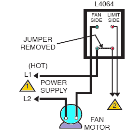 The diagram at left shows how to wire the Honeywell L4064B combination furnace control when it is used to control low-voltage equipment.
This tab is found protruding from the control near the center of the bottom of its face. You'll see embossed on the control above this tab the words "Remove for Low Voltage".
Newer versions of this control have a brass jumper in the same location. The brass jumper is broken off for low-voltage use and is not replaceable once it has been removed.
The fan or furnace blower motor is controlled by the two left connections (green dots).
The furnace limit switch which will turnoff the burner if the temperature limit is reached is controlled by the two right connections (red dots). Here the furnace limit switch is controlling a low-voltage device such as a heating furnace gas valve. The colored triangles refer to notes given below.
Notes:
- Be sure to add a power disconnect switch and overload (fuse or circuit breaker) protectionOn this circuit. Note that the jumper or paper tab has been left in place.
- Wires to control low-voltage equipment - in this case the jumper has been removed.
Before wiring this or any control be sure to obtain the latest data from the manufacturer of the control and the furnace on which it is to be installed.
Additional installation details for the Honeywell L4064B Combination Fan Limit control in the latest form are available from Honeywell.
After wiring this control make sure you've use the proper settings by reading
over FAN LIMIT CONTROL SETTINGS and then be sure you test the combination fan and limit switch for safe and proper operation.
...
How to Check that the Fan Limit Switch is Working Properly
Excerpting from the 2017 document given below:
When installation is complete, disconnect the fan motor circuit at the L4064.
Turn on power and set thermostat to call for heat.
Burner should come on and limit controller should shut burner off when plenum temperature reaches the limit set point.
Turn off power, reconnect the fan switch, turn on power and again set thermostat to call for heat.
The fan should start when plenum temperature has reached fan-on setting.
...
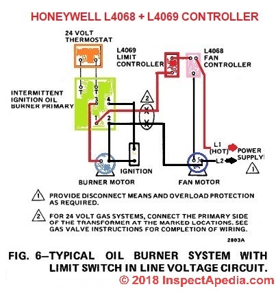
Honeywell L4068 & 4069 Fan & Furnace Controller Wiring
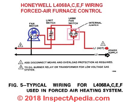
- HONEYWELL L4068A,C,E,F & L6068A,D FAN CONTROLS [PDF] (1976) installation and wiring manual.
The Honeywell L4068A,C,E,Ffan controls operate the furnace fan motor in response to plenum temperature in forced air heating systems.
L4068G attic fan control operates an attic ventilation fan in response to attic air temperature.
The L6068 air switch is used in downflow furnaces to prevent reverse air circulation and to provide protection against excessive temperatures caused by vlogged filters.
The L6068 can also be used to control a 2- Speed fan.
...
Nordyne Fan Limit Controls
Shown below, the NORDYNE THERM O DISC 40T611 DUO-THERM fan limit control switch and thermal sensor.
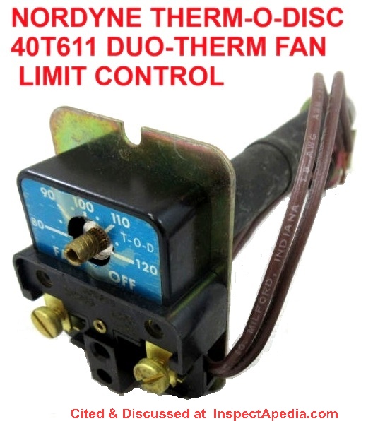
Nordyne Therm-O-Disc Fan Control Standard settings
- High limit - 180°F to 200°F
- FAN OFF - 90°F to 100°F
- FAN ON - 120°F to 130°F
It may be possible to replace the Nordyne Therm O Disc limit control with the universal Resideo/Honeywell L4064B limit control switch. When choosing a replacement for the Nordyne fan limit switch, bee sure to match the 5 1/2" long original sensor length.
...
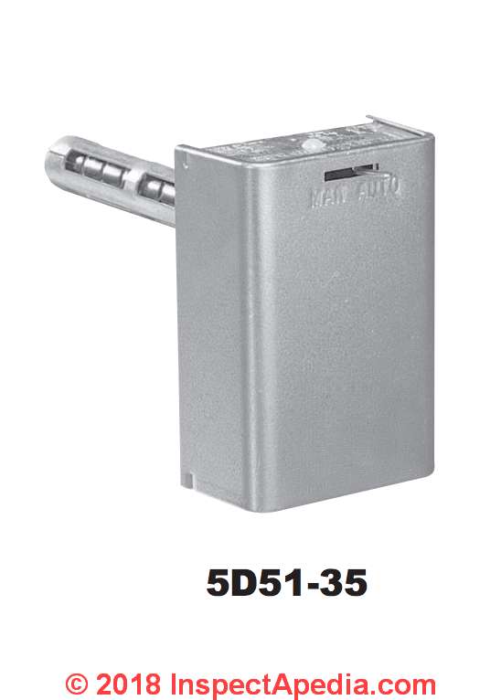
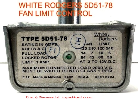
Wiring the White Rodgers 5D-series Fan Limit Controller
- WHITE RODGERS DISC THERMOSTATS [PDF] product specifications, limit controls, fan controls, disc thermostats
- WHITE RODGERS 3L09 SERIES BOARD MOUNT LIMIT CONTROLS [PDF] 1/2" bimetal disc models & features
- WHITE RODGERS 5D51 UNIVERSAL FAN & LIMIT CONTROL [PDF] ] retrieved 2018/02/08 original source: https://www.grainger.com/ec/pdf/2E139_1.pdf and illustrated here and in more detail below.
- WHITE RODGERS 50A55-842 SYSTEM CONTROL WIRING [PDF]
The 50A55-843 is an automatic gas interrupted ignition control that employs a microprocessor to continually monitor, analyze, and control the proper operation of the gas burner, inducer, and fan.
Signals interpreted during continual surveillance of the thermostat and flame sensing element initiate automatic ignition of the burner, sensing of the flame, and shut-off during normal operation. - WHITE RODGERS 757-1 / 758-1 FAN CONTROL & LIMIT CONTROL [PDF] retrieved 2018/03/04 original source http://www.emersonclimate.com/Documents/White-Rodgers/instruction_sheets/0037-5788.pdf
- WHITE RODGERS UNIVERSAL FAN LIMIT CONTROLLER SPECIFICATIONS [PDF] gives full list of models and features
- WHITE RODGERS 21M51U-843 UNIVERSAL INTEGRATED HSI
FURNACE CONTROL KIT [PDF] wiring diagrams, for two-stage, integrated 3-speed (PSC) furnace controller, White Rodgers Corp., Replaces White-Rodgers 50M51-242 and 50M61-XXX's Two-Stage
HSI Systems with 80V or 120V Ignitors
Includes a diagnostic table de-coding the green, amber, and red LED flash codes used in troubleshooting the furnace. - WHITE-RODGERS-FAN-LIMIT-CONTROL-5D51-35-78-90-INSTALLATION [PDF] White-Rodgers Division
Emerson Electric Co.
9797 Reavis Rd., St. Louis, Mo. 63123-5398
(314) 577-1300, Fax (314) 577-1517
9999 Hwy. 48, Markham, Ont. L3P 3J3
(905) 475-4653, Fax (905) 475-4625 retrived 2018/03/04, original source: http://www.royallfurnace.com/support/components/fan-limit-switch.pdf in English and French.
Excerpts:
This fan and limit control combines, in one enclosure, a fan switch with an adjustable differential which operates the blower in a forced warm air furnace and a limit switch with a fixed differential which automatically shuts off the burner if the furnace temperature exceeds a predetermined high point.
A summer fan switch is incorporated in this control to provide a convenient method for manual operation of the fan for air circulation during the summer.
Cette commande de ventilateur et de limite combine, dans un seul boîtier, un interrupteur de ventilateur avec une différence réglable qui fait fonctionner le ventilateur dans un système à air pulsé et un interrupteur de limite à différence fixe pour arrêter la chaudière si sa température dépasse une température élevée spécifiée.
Un interrupteur de ventilation pour l’été est incorporé dans cette commande pour fournir une méthode pratique d’utilisation manuelle du ventilateur pour faire circuler l’air en été.
Watch out: To prevent electrical shock and/or equipment
damage, disconnect electric power to system at
main fuse or circuit breaker box until installation
is complete.
Label all wires prior to disconnection when servicing
controls. Wiring errors can cause improper
and dangerous operation.
Following installation or replacement, follow
appliance manufacturers’ recommended installation/service
instructions to insure proper operation.
Do not use on circuits exceeding specified voltages.
Higher voltages will damage control and
could cause shock or fire hazard.
If in doubt about whether your wiring is millivolt,
low or line voltage, have it inspected by a qualified
heating and air conditioning contractor or a
licensed electrician.
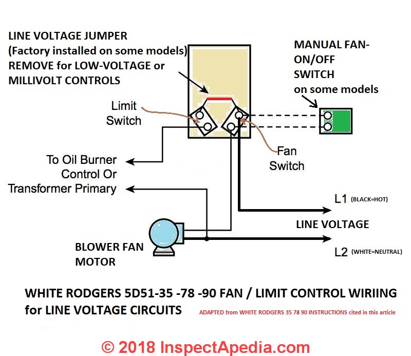
Above: Wiring diagram for the White Rodgers Fan Limit Control used at line voltage. Adapted from the White Rodgers 5D51 installation instructions cited here.
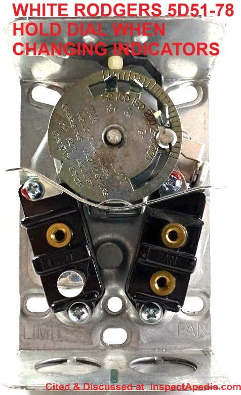
Above and below: White Rodgers 5D51-78 Fan Limit Control Interior and label markings. Notice the company's warning: HOLD DIAL WHEN CHANGING INDICATORS & DO NOT ADJUST SAFETY STOP.
Below: Wiring diagram for the White Rodgers Fan Limit Control used with low voltage equipment.
Note that the jumper is remoed for use with low voltage equipment, also adapted from the White Rodgers 5D51 installation instructions cited here.
- INSTRUCTIONS for REPLACING a WHITE RODGERS FAN LIMIT THERMOSTATIC CONTROL [PDF] TECHNICAL SUPPORT HEATING, Powrmatic Ltd, Hort Bridge, Ilminster, Somerset, TA19 9PS UK David Guest 01460 53535 davidguest@powrmatic.co.uk retrieved 2018/03/04, original source: http://www.powrmatic.co.uk/wp-content/uploads/TB118.0717-Fan-Limit-Stat-LQ.pdf
- Also see WHITE RODGERS CONTROLS & MANUALS - all
...
Other Limit Controls, Wiring & General Information
Warning on Wiring Limit Controls and Switches in Reverse Polarity
is it ok to wire the limit switch backwards with wires reversed in polarity from the instructions?
Line voltage is wired at the bottom left push-in terminal.
Load voltage (to the fan) is wired at the upper left push-in terminal.
What happens if these are reversed & will it ruin the limit control switch 2018/10/01 John Ford
Reply: do not wire switches in reverse polarity: damage risk
Thanks for a critical question, John as we've all pushed a wire into the wrong connector from time to time.
Watch out: Warning about wiring fan limit switches or other controls in reversed polarity:
I don't know what specific fan limit switch you are using reverse wiring effects and I suspect that the risk of damage from wiring in reverse polarity is manufacturer and model-dependent as well as dependent on an additional detail I'll note. Here are some general remarks:
Most switches will "work" 'when wired in reverse polarity or "backwards" in that they turn-on or off the switched device as needed.
However wiring in reverse polarity can damage electrical components and can also be unsafe.
A review of THE BASICS of LIMIT SWITCHES [PDF] an excellent document on limit switches by Eaton, cited in detail below, reminds us that mis-wiring a switch as you asked can cause arcing when the switch operates; that arcing in turn can damage the switch or devices connected to it.
Excerpt:
Limit Control Wiring Polarity Observations
Polarity is a term which is used to describe the relationship between the load and line connections in a multicircuit switch.
Take a set of contacts with terminals that are made electrically common. If a line to line short circuit does not occur, these contacts are said to be connected to the same polarity.
If a line to line short circuit does occur the contacts are said to be of opposite polarity.
Some limit switches have their sets of contacts isolated from each other on the same pole. They are said to have electrically isolated outputs and are labeled as such.
Most devices, however, do not have isolated sets of contacts on the same pole and care must be taken to observe polarity.
Failure to do so can cause permanent damage to the switch, the wiring or both.
Additional remarks:
In some electronic devices leaving a live connection to the side of a circuit that's normally not energized can sometimes cause damage to a circuit or circuit board - a classic example is the effect of stray currents on the neutral wire in a circuit that damage an appliance or trip an AFCI.
When wired improperly the heating system is also unsafe. For example as you'll see in the Honeywell schematic I include below, if you reverse line and load wiring you are keeping the motor and other parts of the system always "energized" - that condition, combined with any of a number of errors or events, could shock someone.
Here is what Honeywell says, using the L4068A-series controller as an example
Connect the “hot” wire from the power supply to the upper left terminal. On L4068, connect the fan motor to the bottom terminal (marked LOAD); connect limit switch, if wired in the line voltage circuit, to the upper right terminal.
References
- Eaton, THE BASICS of LIMIT SWITCHES, [PDF] Eaton, a power management company, corporate headquarters in Dublin, Ireland, Tel: US: +1-877-386-2273, 800-426-9184, Canada
+1-800-268-3578 International
+1-828-651-0786, retrieved 2018/10/01, original source:
Note: excellent, comprehensive review of wide range of types of limit switches and their operation.
Excerpt from Introduction: Presence Sensing is the act of detecting the presence or absence of an object with a contact or non-contact sensing device.
The sensors then produce an electrical output signal that can be used to control equip-ment or processes.
Mechanical limit switches are contact sensing devices widely used for detecting the presence or position of objects in industrial applications.
The term limit switch is derived from the operation of the device it-self.
As an object (or target) makes contact with the operator of the switch, it eventually moves the actuator to the "limit" where the elec-trical contacts change state. Through this mechanical action, electrical contacts are either opened (in a normally closed circuit) or closed (in a normally open circuit).
Inductive proximity, capacitive proximity, and photoelectric sensors perform this same process through noncontact sensing. - NORA, LIMIT CONTROLS & THERMOSTATS, [PDF] National Oil Heat Research Alliance, 600 Cameron Street,
Alexandria, VA 22314 USA, Tel: 703.340.1660,
Website: https://noraweb.org/contact/, educational module, retrieved 2018/10/01, original source: https://noraweb.org/wp-content/uploads/2016/10/NORA-Silver-Chapter-12.pdf
Website Excerpt:
... The National Oilheat Research Alliance, ... was authorized by Congress in 2000 to provide funding that would allow the oilheating industry to provide more efficient and more reliable heat and hot water to the American Consumers. As a government sanctioned “check-off” program, $0.002 is collected at the wholesale level on every gallon of heating oil sold. While it is mandatory, the benefits greatly outweigh the minimal cost.
The four key arms of NORA are Consumer Education, Professional Education, improving energy efficiency and safety, and Research Consumer Education allows NORA to reach out to the consumer and show that oilheat is a clean, safe, efficient and modern form of heating.
This communication is essential to the industry’s survival.
Professional education, through the Technician Certification Program, provides continuing education, training and certification for oilheat service technicians. Lastly, NORA funding has helped a number of manufacturers to develop highly efficient heating equipment, such as condensing boilers and furnaces, variable speed furnaces, variable burners and number of other technologically advanced, highly efficient products.
...
Reader Comments, Questions & Answers About The Article Above
Below you will find questions and answers previously posted on this page at its page bottom reader comment box.
Reader Q&A - also see RECOMMENDED ARTICLES & FAQs
What happens is you reverse the wires on a White Rodgers snap disc fan control?
What happens is you reverse the wires on a White Rodgers snap disc fan control? On 2020-11-01 by Gary
Reply by (mod) -
Thanks for the snap disc control wiring question, Gary.
Where a snap disc switch is simply opening or closing a circuit it's usually doing so by interrupting a single wire. In that case swapping the wires is likely to have no effect on the switch operation.
For example a switch that opens on temperature rise will simply interrupt a burner power circuit.
Watch out: it's not always the case that the wire connections make no difference on other controls or wiring connections: check the instructions that come with the specific control.
For example in some cases leaving power always present on the wrong side of some circuit boards can over time damage a board.
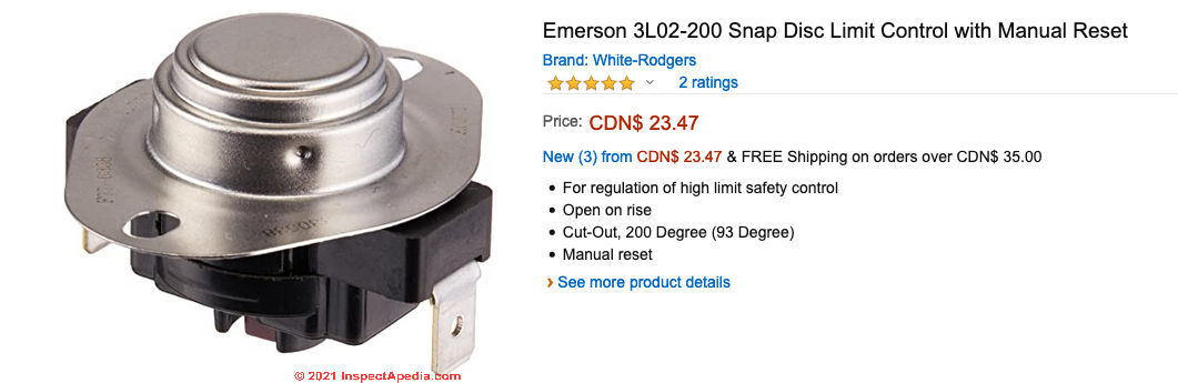
Another snap disc control example from Emerson is shown above. Notice that there's no identification distinction on the two wiring terminals.
Can you connect 120 volts to a 3L0 -190 white Rogers snap disc
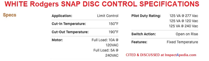
Can you connect 120 volts to a 3L0 -190 white Rogers snap disc limit control On 2020-09-21 by Anonymous
by (mod) - here's the specifivcdations: note the voltage
Anon:
White Rogers offers this spec - note the voltages given
How do you set the fan speed?
How do you control the speed of your furnace fan? - 2020-01-18 by jim
Reply by (mod) -
Jim,
Many home heating furnace blower fans run only at one speed.
Some have a multi-speed fan that runs at different speeds under control of the circuit board in the air handler, or the fan speed may vary automatically depending on whether or not you are in heating or in cooling mode.
Some air handler circuit boards indeed include little dip switches or jumper pins that allow the service technician to set the fan speed(s) if the fan motor supports them.
See our article BLOWER FAN SPEED SETTINGS
for step by step instructions and for links to a number of air handler manuals with more instructions on setting the fan speed
Here is an example for York air handlers that explains the details of setting of a variable fan speed on the control board [PDF]
Give me the brand and model of your air handler and I will look for its specific instructions.
Carrier Day and Night FAU (Fan Air Unit) Stopped working: what do I test?
I installed a new ICM 281 for a Carrier Day and Night FAU.
When I turn on the power, the blower fan started running for 1-2 minutes, the hot surface igniter light up red hot, the burners ignited while the blower kept running.
Everything seemed to work fine.
A few days later, the FAU stopped working.
Shouldn't the surface igniter becomes red hot first, then the burners light and run for a few minutes, before the blower starts running to push the hot air up into the unit?
What should I test to see why the FAU stopped working? On 2019-01-19 Joe T.
-
Thanks. J.
Reply by (mod) - when furnace fan does not turn-on follow these diagnostic steps
Revised
Joe
The fan comes on after the plenum is warmed. Not before - on a heating application.
Otherwise the unit would blow cold air on occupants.
Diagnosis and repair details areWatch the fan limit control to see if it's rotating to the FAN ON position.
...
Continue reading at FAN LIMIT SWITCH TROUBLESHOOTING or select a topic from the closely-related articles below, or see the complete ARTICLE INDEX.
Or see FAN LIMIT SWITCH INSTALLATION & WIRING FAQs - questions & answers posted originally on this page
Or see these
Recommended Articles
- AIR HANDLER / BLOWER UNITS - home
- BLOWER FAN OPERATION & TESTING if your heating or cooling system blower fan itself appears not to be working
- BLOWER FAN SPEED SETTINGS
- FAN, AIR HANDLER BLOWER UNIT
- FAN LIMIT SWITCH GUIDE
- FAN LIMIT SWITCH TROUBLESHOOTING
- FAN MOTOR START CAPACITORS
- FAN, COMPRESSOR / CONDENSER UNIT
- FAN ENERGY INDEX FEI
- FAN LIMIT SWITCH GUIDE - home
- FAN LIMIT CONTROL SETTINGS
- FAN LIMIT SWITCH INSTALLATION & WIRING MANUALS
- FAN LIMIT SWITCH TROUBLESHOOTING
- FAN RUNS ONLY ON FAN-ON / MAN
- FAN WONT STOP - LIMIT SWITCH
- FAN WONT STOP - THERMOSTAT SWITCH
- FURNACE BLOWS COLD AIR
- FURNACE FAN CYCLES AFTER HEAT
- FURNACE FAN CYCLES DURING HEAT
- FURNACE FAN STOPS EARLY
- FURNACE or A/C BLOWER FAN WONT START
- FURNACE or A/C BLOWER FAN WONT STOP
- WOOD FURNACE FAN LIMIT CONTROL
- FAN MOTOR START CAPACITORS
- FAN NOISES, HVAC
- FAN ON AUTO MAN THERMOSTAT SWITCH
- FAN ON SWITCH ADDITION
- FAN WONT STOP - THERMOSTAT SWITCH
- FURNACE CONTROLS & SWITCHES
- MANUALS & PARTS GUIDES - HVAC - home
- MANUALS for HEATING & A/C SYSTEM CONTROLS - home
- UNDERSIZED RETURN DUCTS - not enough return air
Suggested citation for this web page
FAN LIMIT SWITCH INSTALLATION & WIRING MANUALS at InspectApedia.com - online encyclopedia of building & environmental inspection, testing, diagnosis, repair, & problem prevention advice.
Or see this
INDEX to RELATED ARTICLES: ARTICLE INDEX to HEATING FURNACES
Or use the SEARCH BOX found below to Ask a Question or Search InspectApedia
Ask a Question or Search InspectApedia
Questions & answers or comments about how to hook up or wire the furnace blower fan limit control switch.
Try the search box just below, or if you prefer, post a question or comment in the Comments box below and we will respond promptly.
Search the InspectApedia website
Note: appearance of your Comment below may be delayed: if your comment contains an image, photograph, web link, or text that looks to the software as if it might be a web link, your posting will appear after it has been approved by a moderator. Apologies for the delay.
Only one image can be added per comment but you can post as many comments, and therefore images, as you like.
You will not receive a notification when a response to your question has been posted.
Please bookmark this page to make it easy for you to check back for our response.
IF above you see "Comment Form is loading comments..." then COMMENT BOX - countable.ca / bawkbox.com IS NOT WORKING.
In any case you are welcome to send an email directly to us at InspectApedia.com at editor@inspectApedia.com
We'll reply to you directly. Please help us help you by noting, in your email, the URL of the InspectApedia page where you wanted to comment.
Citations & References
In addition to any citations in the article above, a full list is available on request.
- "Warm Air Heating Systems". Instructional Technologies Institute, Inc., 145 "D" Grassy Plain St., Bethel, CT 06801 800/227-1663 [home inspection training material] 1987
- Heating, Ventilating, and Air Conditioning Volume I, Heating Fundamentals,
- Thanks to reader Dan Somerville for technical editing assistance 01/09/10
- Honeywell Corporation, Minneapolis, MN 55408. Honeywell has sales offices in all principal cities in the world and has manufacturing facilities in Australia, Canada, Finland, France, Germany, Japan, Mexico, Netherlands, Spain, Taiwan, United Kingdom, U.S.A. Honeywell Form Number 60-0450 7-75, residential division. Honeywell's latest product data for this type of control can be found in English at http://customer.honeywell.com/Techlit/Pdf/69-0000s/69-0117.pdf
- In addition to citations & references found in this article, see the research citations given at the end of the related articles found at our suggested
CONTINUE READING or RECOMMENDED ARTICLES.
- Carson, Dunlop & Associates Ltd., 120 Carlton Street Suite 407, Toronto ON M5A 4K2. Tel: (416) 964-9415 1-800-268-7070 Email: info@carsondunlop.com. Alan Carson is a past president of ASHI, the American Society of Home Inspectors.
Thanks to Alan Carson and Bob Dunlop, for permission for InspectAPedia to use text excerpts from The HOME REFERENCE BOOK - the Encyclopedia of Homes and to use illustrations from The ILLUSTRATED HOME .
Carson Dunlop Associates provides extensive home inspection education and report writing material. In gratitude we provide links to tsome Carson Dunlop Associates products and services.
 |
HOME | ABOUT | ASK a QUESTION | CONTACT | CONTENT USE POLICY | DESCRIPTION | POLICIES | PRIVACY | |
| © 2026 - 1985 Publisher InspectApedia.com - Daniel Friedman | |||||||||