 Fan Limit Control Installation & Wiring FAQs
Replacements for Furnace Fan Limit Control Switches
Wiring details for the furnace an limit control

- POST a QUESTION or COMMENT about how to hook up or wire the furnace blower fan limit control switch
Fan limit switch wiring questions & answers.
This article series describes in detail the installation & wiring of furnace combination controls, also commonly called the "fan limit switch" on warm air heating systems.
InspectAPedia tolerates no conflicts of interest. We have no relationship with advertisers, products, or services discussed at this website.
- Daniel Friedman, Publisher/Editor/Author - See WHO ARE WE?
Furnace Combination Control Fan Limit Switch Wiring FAQs

These questions & answers or comments about how to hook up or wire the furnace blower fan limit control switch were posted originally
at FAN LIMIT SWITCH INSTALLATION & WIRING MANUALS - be sure to review that article.
There you will also find links to detailed wiring instructions for all brands and models of fan limit controllers.
Below is our index to reader Q&A about furnace fan limit switch installation & wiring.
Article Index
- BLOWER FAN WONT START FAQs
- BLOWER FAN WONT STOP FAQs
- BROKEN LIMIT SWITCH WIRE, BLOWER WON'T RUN
- LINE / LOAD WIRE CONNECTIONS at FAN LIMIT SWITCH
- REPLACEMENT for COLUMBUS ELECTRIC CTC FAN LIMIT CONTROL
- REPLACEMENT for HONEYWELL CT50K FAN LIMIT CONTROL - on a 50 year old GE Furnace
- REPLACEMENT for HONEYWELL L4064B FAN LIMIT SWITCH
- REPLACEMENT for HONEYWELL L4064T FAN LIMIT CONTROL
- REPLACEMENT for HONEYWELL L4064W FAN LIMIT SWITCH
- REPLACEMENT for HONEYWELL L4064Y FAN LIMIT CONTROL
- REPLACEMENT for RHEEM RGVA-09EA FAN LIMIT CONTROL
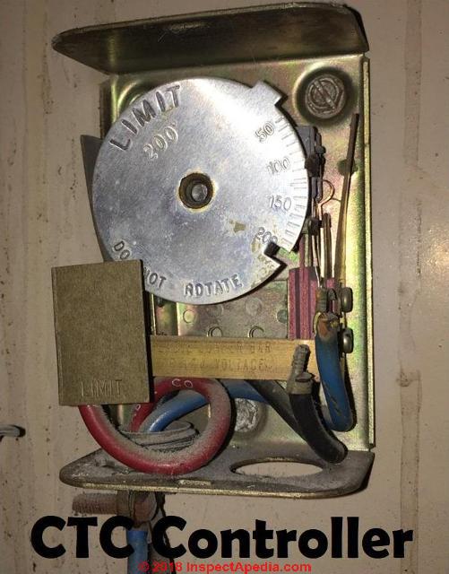
- ROTATING DIAL DAMAGE on FAN LIMIT CONTROL - Watch out: manually rotating the dial can damage it and may make the heater unsafe
- FAN LIMIT CONTROLS on MULTIPLE HEATERS - oil or gas furnace with coal or wood stove
- FAN LIMIT SWITCH JUMPER TAB FAQs
- FAN LIMIT SWITCH TROUBLESHOOTING FAQs - diagnostic Q&A
- UNUSED WIRES WHEN REPLACE a L4064W with a L4064B
- WESCO ELECTRIC FURNACE FAN LIMIT WIRING
...
Tip: if your fan limit control switch does not seem to be working properly, see FAN LIMIT SWITCH TROUBLESHOOTING
Tip: If you need the manual for your fan limit control to see wiring or other details, see FAN LIMIT SWITCH INSTALLATION & WIRING MANUALS
Also see our index to all fan limit control switch questions & answers found at FAN LIMIT SWITCH FAQs
...
Wesco electric furnace ATR-20-204VAC wiring diagram needed
SHARKY
I have a 1970 Wesco electric furnace model# atr-20 240vac. 4 elements total.
A total electricity hog with today's power/ electric prices indeed. A great high quality fully american made electric furnace though.
These were made for 1972 electric rates for sure!
Can I disconnect 1 or 2 elements to save on 50% of my power bill?
Thanks and where can i get the original schematics and owners manual for this unit?
Reply: where to find parts & product information for older Wesco Electric Furnaces
Wesco is currently an electrical products distributor and is no longer listing electric furnaces among their products.
But possibly the company has information on its discontinued products,
- Wesco Corporation, 225 West Station Square Drive, Suite 700, Pittsburgh, PA 15219 , can also be contacted at (412) 454-2200 or at their Website: http://www.wesco.com
The company does supply heating units for electric furnaces through this website: www.wescodirect.com
Keep in mind that on many electric furnaces a number of the parts are generic so heaters, controls, sequencers can often be replaced with an equivalent unit. Try taking old parts to your local HVAC supplier.
...
Fan Limit Control Wiring - Blower Fan Trouble FAQs
Furnace Blower fan won't start - wiring snafu?
I have an old style furnace/ac. The furnace has a honeywell combination furnace control type L4064 on it.
When my A/C kicks in, the blower does not kick in.
I also cannot turn my fan onto the continuous mode on my thermostat at all.
But if I pull the manual button on the Honeywell control, the blower will run.
Does this Honeywell control box control the fan motor in relationship to the ac as well. The blower works fine when it is in the heat mode.
Reply:
That fan limit switch that forces the fan to run is a helpful diagnostic - it tells us that the problem you have is not in the fan assembly nor fan motor since those will run. So I infer there is a problem with your thermostat, thermostat wiring, thermostat transformer, or a control circuit in the air conditioner.
Start by checking the wiring.
To be more clear: the fan limit switch is a heating control that controls the fan on and off in heating mode.But when you pull the (usually white) manual button on the limit switch, that's an electrical override that simply forces the fan to the "ON" or "run" condition. It's typically not part of the cooling circuit.
Reader follow-up: the problem was a broken wire
Problem solved: broken electrical wire
Found the culprit, was a broken brown wire coming out of the main electrical junction box inside the cabinet of the furnace. Did a quick patch job and yohoo, blower motor works in manual mode on thermostat now. Very much appreciated !
Thank You from So. WisconsinReply:
Thanks for the feedback Tony - your comment reminds us that if a check for voltage at the blower fan does NOT find voltage and we are sure that power is on to the unit, we need to check for a disconnected or broken wire just as you did.
I Suspect that the fan limit switch wiring is causing my furnace to fail
My furnace fan sometimes runs steady and next it works fine and a few days later the same thing happens can a fan limit switch work good and than not or they just go bad permanently On 2021-04-13 by ivan girouard
by (mod) - look first for a loose wire / bad connection
@ivan girouard,
Possibly,
I would look first for a loose wire / bad connection at the fan limit control.
I would also check the furnace burner condition: soot or improper combustion could be turning off the unit.
I'd also check for a loose blower door switch or bad blower door switch contact; sometimes something as simple as a door that's not fully shut can turn off the furnace blower intermittently.by Cory - found faulty wire connection to gas valve
Ok so I went over everything again and I ended up finding a faulty connection with my wire going to my gas valve,it is a push in and lock stlye connection so to the naked eye it looked like it was in correctly ,you live you learn I guess thanks for all the help it is appreciated.
by (mod) -
Good going Cory. What you found will help other readers
- good debugging.Loose wiring connections are perhaps the most common fault on many systems.
...
How to Replace a Bad Fan Limit Control
 @InspectApedia Publisher,
My furnace was using this now obsolete Honeywell CT50K fan limit control described in the literature as
"Honeywell Model CT50K Special Feature, Low Temperature, Great for use in garages or outdoor buildings, Wide temperature range for setting to desired temperature, Bimetal temperature sensor offers simple and hassle-free operation"
What install looked like before all the vent pipes replaced, (in same configuration). Again, just trying to tweak install for max efficiency, working with what we have.
It's pumbed will city natural gas off a Tee feeding the homes furnace. actually been in operation off and on for 15+ years probably only a few years all winter at the low setting of around 40°+ using an old round gold honeywell mercury switch thermostat at its lowest setting.
Last December swapped that thermostat for a Honeywell electronic thermostat that goes down to 35° for this type of application. Seemed to perform ok from listening to my dad, uril last week when I found all the flue venting pipes corroded and leaking.
Replaced all those last week cleaned inside and out and added a 20x25x1 filter over the intake. That's when I discovered the fan speed switch and limit switch, undoubtedly still set where they were when it was installed in a ~2000 sq foot walkout rambler at the time.
I have a some pictures of the wiring diagram inside the maintenance panel and other details. I'll try to post another pic with this reply....
I will try to decode the pictures I took later but think what I can read says 100,000 btu, fan type 70-105° temp rise @
static . 20, . It is a two car garage real rough guess of ~22ft x 26ft with a ~8-9ft ceiling? - On 2023-12-04 by Zika
by InspectApedia Publisher
@Zika,
This looks like an old furnace possibly repurposed from somewhere else. A couple of preliminary questions
What's the fuel, oil, gas?
Is this a new application or do you have some experience using this furnace in this cold garage?
Do you have a thermostat that you can set to turn on at the low maintenance temperature that you were describing?by Zika
So I have an old GE furnace (60+ yrs old) installed in a MN garage to keep the temp around 35°-38°, the fan limit dial is set to 90°, the range is 80°-135°.
There is also a big toggle switch for high and low fan speed set to high.
Outside temp will vary from about ~ -10°- +40° the next 4 months. The garage and door is insulated.
The plenum is an open ~18" x 18" grate at the ceiling pointing forward.
Any advice on fan limit setting and speed in this install?
It's a garage and I only turn it up occasionally to 60° to work in there for a few hours otherwise it's just keeping the cars and concrete slab above freezing... Thanks!
by InspectApedia DF (mod) - running a gas furnace in a garage kept at low temperatures: settings & risks
@Zika,
OK those additional details are helpful, and important.
Thoughts on running a gas furnace in a garage kept at low temperatures: settings & risks
The GE fan limit switch in your photo is at a reasonable setting for the use you're making of the furnace and it ought to work "as is".
However if you set a bit higher FAN-OFF temp that might seem to be appropriate for running the system in a very cold garage.If you need to replace that obsolete Honeywell CT50K fan limit controller, you can use the HONEYWELL L4064B, L4064R UNIVERSAL COMBINATION FAN & LIMIT CONTROLLER
Here's my thinking and OPINION (I'm not the world's expert on this point)
1. When the temperature drops to or below the thermostat setting the thermostat - in essence a simple on-off switch - calls for heat at the furnace controls (including the fan limit control).
2. The furnace will turn ON and will continue to run until EITHER the thermostat is satisfied OR the furnace hot air supply plenum temperature (where the fan limit switch is normally mounted) reaches the FAN OFF temperature.
I suspect, and this is how furnaces usually work, that in a cold garage, on a call for heat the furnace will simply run continuously until the thermostat is satisfied. That's because the cold air returning from the garage keeps cooling down the furnace plenum.
So it's probably irrelevant, but in concept, we set the fan OFF to a higher temperature that should mean that on a call for heat the burner would run longer before turning off.
So in sum you should watch how the furnace runs when the thermostat calls for heat. IF you see the furnace cycling on and off frequently you might try raising the fan off temp.
Watch out: A concern:
Running any heating equipment, but especially a gas fueled furnace heater and at settings that might give a short and infrequent on-cycle (which is indeed might be the case when you're keeping the thermostat set to a very low temperature) risks corrosion in the furnace at its heat exchanger (this is VERY dangerous and risks fatal carbon monoxide poisoning if the heat exchanger leaks) and also corrosion in its exhaust vent or flue.
That's because corrosive condensate in those areas accumulates - they are not being kept warm and dry.
So besides
1. watching the furnace to see if it has long on cycles (best),
2. be sure you have working smoke and carbon monoxide detectors installed, properly located and tested regularly, including in the garage
3. ask your heating service company to have the system inspected and tested by an experienced service technician who knows how to inspect for and test for heat exchanger leaks and any other safety concerns.
Do keep us posted; what you add will help other readers.See more about Ten Steps in the Sequence of Operation of a Furnace Fan Limit Control above in this article.
by InspectApedia Publisher
@Zika,
I am not confident that your heating system is safe, and I add (being cautious and considering how little we know about your system and the expertise of people involved) that unless your friend is trained in gas heat service and heat exchanger testing, you shouldn't bet your life on his inspection.
We've published quite a bit on this question, starting at
HEAT EXCHANGER LEAK TESTSources / Types of CO Detectors that Work at Low Temperatures
We've read that there are two problems using smoke detectors and some CO detectors in low temperature environments: ionization type smoke detectors and battery operated smoke or CO detectors may not be reliable.
However a detector that plugs into a 120VAC wall receptacle should work - at least to avoid the cold battery problem. < Take a look at the Kidde HD135, described in its manual as Kidde HD135
For CO detection at low temperatures you probably need to look at commercial models that are in the $100 - $200. price range. Perhaps a Macurco unit.
by Zika
Thank you for your advice, I will be over there later this week and test it out. Maybe I can convince a friend who has a boiler license to test the heat exchanger.
The flue pipes are 26 gauge galvanized steel. It was that or 30 gauge at the HDepot so I choose the thicker of the two. Fairly sure these aren't meant for flue gas but are for heated air distribution inside a hone.
I do have an AC Carbon Monoxide detector in the garage stamped 2017 on the back so it's reached the ~7 yr expiration date. That will be replaced.
FYI for readers, nearly every CO detector I have looked at has a 40° F minimum operating temperature. If anyone knows of a common affordable residential model that has a lower temperature range I'd love to here about it.
Thanks again! I will have more information on this install and performance next weekend. If you have more questions please post and I'll gather the info and pictures.


...
Find replacement for Honeywell L4064T1103 fan limit switch on a Rheem furnace
I have a model RGUD-135C Rheem furnace. I need to replace the fan/limit switch. The parts call for a Honeywell L4064T1103. I can't seem to find it anywheres.
All I can find is a replacement Honeywell L4064B2236. Is this correct? If this is correct I'm not sure I quite understand the wiring configuration. I have included a wiring diagram from the furnace manual On 2020-01-19 by Tim -
Reply by (mod) -
Tim you can post a copy of the wiring diagram by using the add image button; if you include a link that can appear after moderator approval.
Honeywell gives cross-reference guides for control replacements. The company recommends the L4064B2236/U where the "/U" indicates a "universal" replacement control, meaning it replaces a number of others.
At FAN LIMIT SWITCH INSTALLATION & WIRING - topic home -we give links to all fan limit controllers including all of the Honeywell L4064B models from every generation.
For a new control you'll want to follow the wiring diagrams and instructions found in
HONEYWELL L4064B, L4064R UNIVERSAL COMBINATION FAN & LIMIT CONTROLLER INSTALLATION MANUAL [PDF] (2017)We have specific photos and installation tips for the L4064B Fan Lmit control at HONEYWELL L4064B COMBINATION FURNACE CONTROL WIRING
We list every version and the full history of instructions for the L4064B at HONEYWELL FAN LIMIT CONTROL WIRING GUIDES & MANUALS
How do I know which furnace fan limit replacement limit switch to buy?
We need to replace a limit switch on our oil furnace blower. One of the prongs broke off.
We have since lost the part and eager to get a new one. But without he number for the switch. It is hard. I have a pic but numbers are faded. I can make out a few numbers but that is all. (Oct 25, 2014) Anonymous
Reply: usually you can use a universal control replacement like this one:
You can use the email found at our CONTACT link at page bottom to send us a photo if you like - but limit switches on residential furnaces are pretty standard.
An easy solution would be to give the manufacturer of your furnace a call, giving them the model and serial number of your unit - they can tell you which limit switch they prefer.
Most likely the service tech will use one of Honeywell's recommended "universal" fan limit controls - like this one
HONEYWELL L4064B, L4064R UNIVERSAL COMBINATION FAN & LIMIT CONTROLLER INSTALLATION MANUAL [PDF] (2017)
...
How to find a replacement for Honeywell Fan Limit Controller, No. L4064Y1177
I am unable to locate a Honeywell Fan Limit Controller, No. L4064Y1177 and would like to know if there is an alternative or a suitable replacement that will fix my Furnace: an Intercity MHGE125BK01? On 2018-12-18 by Sarah
by (mod) - Replacement for a Honeywell Fan Limit Controller
Sarah At FAN LIMIT SWITCH INSTALLATION & WIRING
you will find the replacement for your Honeywell L4064Y and its installation instructions at
HONEYWELL L4064B, L4064R UNIVERSAL COMBINATION FAN & LIMIT CONTROLLER INSTALLATION MANUAL [PDF] (2017)
This L4064B, L4064R limit controller is a universal replacement for older furnace fan limit controllers. Here is the difference between the L4064B and L4064R, excerpting from the document above:
These combination warm air fan and limit controllers are suitable for various types of forced air heating systems. The controllers have 2 switches; one which opens the limit circuit if the plenum temperature exceeds the preset safety limit; it resets automatically. The other switch turns the fan on and off.
The fan is turned on and off according to plenum temperature.
The L4064R has a special high temperature range suitable for gravity heating systems.
All models may be used as limit controllers by wiring only the limit side. Limit contacts are suitable for both line voltage and low voltage. For low voltage applications, the brass jumper must be removed.
...
Follow furnace or burner manufacturer’s instructions, if available.
Maximum element temperature is:
L4064B—350 ºF (177 ºC).
L4064R—250 ºF (121 ºC) above limit setting.
Maximum switch temperature is: L4064B,R—190 ºF (88 ºC).
...
Line & Load Wires, Black, White, Red Wire Connections at the Fan Limit Switch
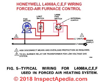
Tip: Above: Typical wiring for the Honeywell L4068A,C,E,F in a forced warm air heating furnace installation, excerpted from the
HONEYWELL L4068A,C,E,F & L6068A,D FAN CONTROLS [PDF] (1976) installation and wiring manual.
Where does the red wire go on my gas heater fan limit switch?
Where does the red wire go? No thermostat. - On 2021-02-17 by Dgone
Answer by by (mod) - here are the three spill switch wire connections
DG in addition to the example wiring diagrams found on this page, the IO manual for the Honeywell Fan Limit controller is given as a free PDF download - as well as manuals for wiring other limit switches.
Example
HONEYWELL L4068A,C,E,F & L6068A,D FAN CONTROLS [PDF] (1976) installation and wiring manual.
Which wire (black or white) is the line voltage and which one is the load voltage for the fan?
How do you determine which wire (black or white) is the line voltage and which one is the load voltage for the fan.
How could I check with a multimeter? (Mar 26, 2014) Ralph-NY
Reply: black for line and white for load
Ralph
by convention we use black for line and white for load.
To check, and provided you know how to use a DMM or VOM safely, one could check for voltage on either wire. The one containig voltage is the "Line" wire.
Start with a simple neon tester for voltage as discussed at
Where to connect the black wire coming from my Honeywell Fan Limiter switch
Please tell me where to connect the black wire coming from my Honeywell Fan Limiter switch, model L4064.
It goes to the 24 volt relay, but I do not know which terminal to connect it to.
Does it go to the armateur or to the top or bottom terminal of the single pole double throw relay. or does it go some place else? (Oct 4, 2011) Weeks Parker
Reply:
Weeks I don't quite understand the options in your question, but indeed the typical fan limit switch wiring is described and illustrated with schematics in the article above as well as in the installation pamphlet for the fan limit switch and usually also right inside the limit switch cover itself.
Black is usually connected to line voltage and the white to the load side of the switch.
I'm always nervous about giving very specific wiring instructions like "where do I connect the black wire" because being offsite and just reading someone's message I have no confidence that I know for sure how the "black wire" is connected at its other end.
What happens if LINE & LOAD wires are reversed at the fan limit control switch?
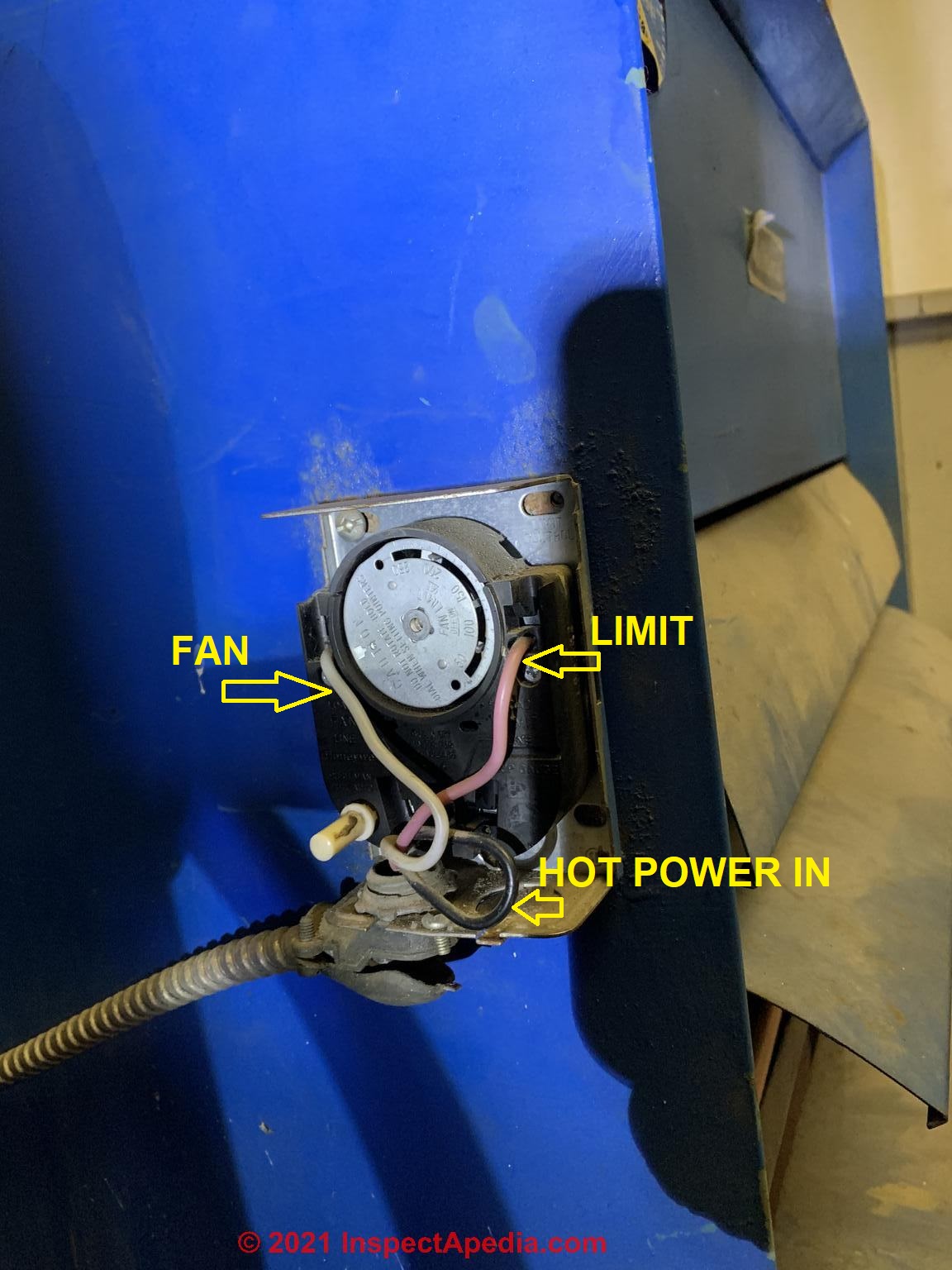
Line voltage is wired at the bottom left push-in terminal.
Load voltage (to the fan) is wired at the upper left push-in terminal.
What happens if these are reversed & will it ruin the limit control switch - On 2018-10-01 by John Ford
by (mod) - reversed polarity can cause serious damage
John
Thanks for an important question.
Watch out: The short answer is yes reversed polarity can cause serious damage to electrical components.
*/-9*/
To have space ford a thorough answer I repeat your question and give a detailed reply at
WIRING LIMIT SWITCHES: GENERAL ADVICE - polarity & other issues at the fan limit control
Please take a look and let me know if you have any more questions. - Daniel Friedmanby John Ford - replacing a limit control switch that got wet
Went and checked the two fan wires with a meter & they were definitely reversed.
Ordered a new Limit Control Switch because of the reversed wiring as well as it looks like the Switch might have gotten water on it from an over flowing AC pan backup.
The fan would not shut off after the unit ran, but you could tap on the Switch & the fan would stop. Acted like the spring was not bring the dial all the way to the fan stop point. Thanks for your input. John
Sorry that I did not include the Limit Control Switch # L4064A with No White Button.
by (mod) - Combination Temperature Controller (CTC)
From the details that you given, John, it does sound like switch replacement is completely appropriate.
If you don't already have a copy of the hookup instructions will probably be enclosed with a new Switch.
Or if you like, the wiring instructions for the Honeywell l4064 are also given as a downloadable PDF file as well as described in the article above.The absence of a white button simply means that there is no manual fan on off switch
Which wires go where on the fan limit switch?
I have a very old fan limit switch with only 2 wires a blue and white wire, it went out, bought a new one but it requires 4 wires to hook up how do I wire this? 3 Oct 2015 Harold
Reply:
Harold,
see the fan limit switch wiring article found
...
Troubleshoot or Replace Columbus Electric Furnace Fan Limit Control Switch
I came home today to find my furnace fan running and my "dump" zone blowing for no reason.
My system is circa 1970 dual zone heat and AC. I have to manually change between heat and AC operation. Currently it's set for AC.
Neither of the two thermostats were driving the system on. I took off the cover and checked out the Combination Temperature Controller (CTC).
I tapped on the furnace near the CTC and the damper closed for the dump zone and the fan turned off.
I think I need a replacement CTC but I can't identify what would be compatible. I'd appreciate any feedback on the issue or what to order for a replacement CTC. Please see attached pictures for reference. Thanks for the help in advance! Larry C On 2018-07-25 by Larry C.
Reply by (mod) -
Larry
In the article FAN LIMIT SWITCH INSTALLATION & WIRING MANUALS see the live link for the manual forHONEYWELL L4064B, L4064R UNIVERSAL COMBINATION FAN & LIMIT CONTROLLER INSTALLATION MANUAL PDF] (2017) Honeywell 1985 Douglas Drive North Golden Valley, MN 55422-3992 customer.honeywell.com
That ought to work for you.
I have added what information I can find about Columbus Electric in the article I just cited. Currently Columbus Electric is a division of TPI.
Contact the company directly at
Columbus Electric Division of TPI, PO Box 4973, Johnson City, TN 37602 USA, Tel 800-251-7828, Fax 423-477-0545
or
TPI Corporation, Website: www.tpicorp.com, Tell: 1-800-682-3398. The company's current product lines include Markel Products, Raywall, and Fostoria and a very large range of HVAC equipment and controls.
...
Replacement for Rheem RGVA-09EA fan limit controller
I have a Rheem RGVA-09EA. The home was build around 1984 and the furnace is original.
I need to replace the combination fan and limit controller. The part number that is installed is L4064t 1541. I thought I could replace it with a "Honeywell L4064B 2210 L4064 Fan & Limit 11" 11.5" Furnace Control", but now I'm not sure.
I can't figure out what to do with the two low voltage wires that appear to be in the back part of the controller.
The L4064B only seems to have terminals on the front
The connections you show in your instructions do match the front part of the existing L4064t.
The small red cardboard tag is even still in place. Can you give me some guidance? On 2018-03-01 by Haydn Chambers at Haydn.Chambers@gmail.com
by (mod) - Compare the L4064T 1541 versus L4064T,W, and Y model fan limit controls
Haydn
The original Honeywell L4064T 1541 control was designed to simply turn the fan on 90 seconds after a call for heat, regardless of the actual plenum temperature.
The L4064T,W, and Y models use a bi-metallic spring heater inside the fan switch to "make" (close) the switch contacts independent of the bimetallic temperature sensor probe that inserts into the heating air plenum itself.
These L4064 models needed the TT (TT = thermostat) circuit & wires to do that - using the low voltage circuit to operate the bimetal heater inside the controller switch.
From p. 10 of HONEYWELL L4064A-F, J,R,T,W,Y FAN LIMIT CONTROLLER INSTALLATION [PDF] (1985) [live link to this is given in the article above] we quote this explanation:
----
Operation of the L4064 Fan Limit Control - how it works:
L4064A-F,J,R -- as the plenum temperature rises, the coiled, bimetal sensing element of the control warps and mechanically makes the fan contacts (at the FAN ON temperature setting). During normal operation, the call for heat ends before the LIMIT setting is reached and the fan contacts break as the plenum temperature falls and the FAN OFF setting is reached.
If the call for heat continues until the temperature in the plenum rises to the LIMIT setting, the bimetal element will mechanically break the limit contacts and de-energize the heating control circuit.
L4064T,W,Y -- The operation of the L4064T,W,Y are the same [as the L4064A-F,J,R that I quoted above] except that the controller uses a bimetal heater in the fan switch to make the switch contacts independent of the bimetal sensing element.This heater acts to anticipate the rise in plenum termperature and turns on th fan 20 to 90 seconds* after the thermostat calls for heat. Actual on-time will vary, depending on the voltage applied to the bimetal heater and on the temperature surrounding the fan switch.
* The fan on timing can vary depending on applied voltage and switch ambient.
----
Other Honeywell L4064x control models could still work to control your furnace, by simply stubbing off the TT wires at the control. That means you'll give up the heat anticipation feature provided by the L4064T but of course you could insert your own "anticipation" by simply dropping the FAN ON temperature a bit. (To be extremely cautious about safety you should also ask your furnace manufacturer if they agree.)
You will find other low-voltage thermostat wires from the same thermostat terminals going to a gas or oil burner to actually turn on the burner.
With other L4064x control models the temperature generated by the burner then activates the limit switch.
The 1981 instructions for the L4064T (provided as a live link in the article above) point out that the L4064T might have been used to replace an L4064A or L4064B. I read that to mean that you could also substitute in the reverse direction, installing an L4064A or L4064B (or equivalent) for an old L4064T. Here is an excerpt from that document, p. 8:
Important: To [sic] L4064T uses a bimetal heater to turn on th fan 90 seconds after a call for heat. When the call for heat ends, the fan will continue to run until the fan-off temperature is reached. If the L4064T is used to replace an L4064A or B, the blower fan may circulate cold air until the plenum heats up. No adjustment of the fan-on time is possible.The small red cardboard tag is removed if the control is being used with low voltage wiring systems.
by Haydn
Thank you again for your prompt reply. I have a question concerning your answer. This may sound dumb, but I will go ahead and as
k. When you say, " Other Honeywell L4064x control models could still work to control your furnace, by simply stubbing off the TT wires at the control.", does "stubbing off" simply mean that I would cut the wires and cap them with a wire nut (or other means) to prevent any connectivity to the fan and gas valve via the low voltage wires?
In other words, all I need to do is only connect the 120V wires to the combination switch and disconnect and terminate the low voltage wires appropriately?
Reply by (mod) -
Yes you would either
1. simply put a small twist on connector cap on each of those individual low-voltage wire ends and tape them aside,
or2. follow the wires back to their point of origin and remove them entirely. I'd do option 1. as it's simpler and fine. You could label them as "used on old Honeywell control" if you like.
You'd just connect the 120VAC wires as we've discussed.
This OPINION comes from reading about the control and what those low voltage wires were doing - as best I can see they were running a heater element in the control that in turn caused the fan to turn on "early" regardless of the actual plenum temperature. In fact Honeywell warned that if you installed that older -T control as a substitute for other models there was a risk that it would, at the start of a heat-on cycle, blow cool air on occupants when there was a call for heat.
Send me photos of your control and the wires if you can;
Also if you have a wiring diagram for your furnace and its manual that'd be interesting to review.
You can give Honeywell a call to confirm what we've discussed.by Haydn
Thank you again for your prompt reply. I have a question concerning your answer. This may sound dumb, but I will go ahead and ask.
When you say, " Other Honeywell L4064x control models could still work to control your furnace, by simply stubbing off the TT wires at the control.", does "stubbing off" simply mean that I would cut the wires and cap them with a wire nut (or other means) to prevent any connectivity to the fan and gas valve via the low voltage wires?
In other words, all I need to do is only connect the 120V wires to the combination switch and disconnect and terminate the low voltage wires appropriately?
by (mod) - how to wire a Honeywell L4064B Fan Limit Control to Replace the Honeywell L4064-T
Yes you would either
1. simply put a small twist on connector cap on each of those individual low-voltage wire ends and tape them aside,or
2. follow the wires back to their point of origin and remove them entirely. I'd do option 1. as it's simpler and fine. You could label them as "used on old Honeywell control" if you like.
You'd just connect the 120VAC wires as we've discussed.
This OPINION comes from reading about the control and what those low voltage wires were doing - as best I can see they were running a heater element in the control that in turn caused the fan to turn on "early" regardless of the actual plenum temperature.In fact Honeywell warned that if you installed that older -T control as a substitute for other models there was a risk that it would, at the start of a heat-on cycle, blow cool air on occupants when there was a call for heat.
Send me photos of your control and the wires if you can;
Also if you have a wiring diagram for your furnace and its manual that'd be interesting to review.
You can give Honeywell a call to confirm what we've discussed.
...
What do I do with old unused wires when replacing a L4064W1080 with a L4064B2228 limit control?
I bought a replacement for my L4064W1080. Was told the L4064B2228, is the replacement for it.
There 2 spade connectors on the W1080 that are not on the B2228.
The other end of the cable is connected to terminal block. Can they just be jumpered? On 2017-11-23 by Tom
by (mod) - The Honeywell L4064B222 is a "universal replacement" for older fan limit controllers
Tom,
The Honeywell L4064B222 is a "universal replacement" for your older L4064W1080, as you were told.The controller includes three wiring terminal options so that the controller can be easily connected in a variety of situation.
The controller also includes female wire receptacles at the upper sides used to power an auxiliary device like a humidifier.
Most-likely for your application you only want to connect two wires, the two line voltage wires that operate the blower fan as shown in Honeywell's wiring diagram and instructions.
I would leave the two other wires disconnected.
At the REFERENCES section to FAN LIMIT SWITCH INSTALLATION & WIRING MANUALSw e include a link to the older installation manual for this control.Both the older and the most-recent wiring instructions are given as PDF files there.
My replacement fan limit switch doesn't have all the same connections as the original
I have an old fan/limit switch from Honeywell that has an additional 2 wires (6 total).
The 2 wires are yellow and the schematic shows one going into the fan limit switch in the bottom/center, goes through a heating resistor/fan assist, and exits.
It is in parallel with the safety and gas valve circuit. It is diagramed as a resistor but is called by 2 names: heating resistor & fan assist.
The replacement fan limit switch does not have these extra 2 connections and is similar to yours on this page. Are these 2 connections necessary? Can I just short them or bypass them? Cannot find any info on this. On 2016-01-05 by Joe
I have the same question - On 2017-01-08 by Miguel Burgos
by (mod) - skip the low voltage wires that operated the heater in the L4064-T
Joe, and Miguel,
You can skip the extra two wires but will probably find that one of the following furnace or heating system features is then not working:
1. a pre-heater installed in the furnace may have been installed to cause the blower fan to start sooner - speeding the heat delivery before the furnace air is fully warmed
2. some old Honeywell (L4064-type) switches use the wires for a separate humidifier or dehumidifier.
Be sure that the sensor for your replacement fan limit switch is the proper size, as a wrong length could make the system work improperly or might be unsafe. For example a sensor that touches the supply plenum cabinet won't function properly.
...
Honeywell L4064B Fan Limit Control Replacement
DIY Honeywell Combination Fan & Limit Controls on Warm Air Furnace model number L4064B2848 installation
Hi my dad has a Honeywell Combination Fan & Limit Controls on Warm Air Furnace model number L4064B2848 but im looking for it on amazon ebay and other sites and keep coming up with no results page. Why can't i find this model ? and is there other model that i can use thats the same as that model?
I'm going to have my friend install it but before i buy it if i can find one. I want to make sure im buying the right part.
i can see the flame and i can hear the fan spin but theres no warm heat coming out of the heaters and my dads home is cold :( we cant control it from the thermostats and the scale plate isnt moving anymore? please help me out - (Nov 5, 2014) Anonymous
Reply:
Anon with apology for sounding a bit like a smart alec, I suggest that you want a trained heating service tech to inspect and repair your dad's furnace. We don't yet have a diagnosis of what's wrong, so I can't assume that the fan limit switch you want to replace is even the culprit.
If the burner runs and the blower fan operates, I don't start by suspecting the fan limit switch.
More likely I'd expect disconnected, crushed, or collapsed air ducts to explain why no air is being delivered.
Honeywell gives cross-reference guides for control replacements. The company recommends the L4064B2236/U where the "/U" indicates a "universal" replacement control, meaning it replaces a number of others.
At FAN LIMIT SWITCH INSTALLATION & WIRING - topic home -we give links to all fan limit controllers including all of the Honeywell L4064B models from every generation.
...
How to install a coal stove fan limit switch in parallel with a propane furnace
I'm installing a coal stove beside my "propain" furnace with an enclosed hood over it & ducting it into my cold air return.
I want to install a fan limit switch over the coal stove & wire it in parallel with my furnace fan limit switch so that the new limit switch will run the furnace blower to suck in the warm coal stove air thru the cold air return to circulate it thru the furnace air filter & throughout the house.
I want the set-up to enable either limit switch to control the furnace blower when they sense enough warm air & the demand for heat at the thermostat.
This should be a simple matter of wiring to the power supply & connecting jumper wires from the furnace switch limit side terminals to the coal stove switch limit side terminals.... correct? If not, please advise the correct way to wire the coal stove limit switch to work as expected.
I read my question after I posted it and realized that I hadn't mentioned about connecting a jumper wire between the fan side terminals too. Below is how my question should have read:
This should be a simple matter of wiring to the power supply & connecting jumper wires from the furnace switch limit side & fan side terminals to the coal stove switch limit side & fan side terminals.... correct? If not, please advise the correct way to wire the coal stove limit switch to work as expected. (Nov 16, 2014) Al
Reply:
Watch out: When you use a heating control in any application not intended by the manufacturer your system could be unsafe risking a building fire or death. So if I were doing what you suggest I'd start by giving Honeywell technical support a call to ask if they agree with the approach.
...
...
Continue reading at FAN LIMIT SWITCH INSTALLATION & WIRING MANUALS - topic home, or select a topic from the closely-related articles below, or see the complete ARTICLE INDEX.
Or see these
Recommended Articles
- BLOWER FAN OPERATION & TESTING if your heating or cooling system blower fan itself appears not to be working
- BLOWER FAN SPEED SETTINGS
- FAN, AIR HANDLER BLOWER UNIT
- FAN LIMIT SWITCH GUIDE
- FAN LIMIT SWITCH TROUBLESHOOTING
- FAN LIMIT SWITCH GUIDE - home
- FAN LIMIT CONTROL SETTINGS
- FAN LIMIT SWITCH INSTALLATION & WIRING MANUALS
- FAN LIMIT SWITCH TROUBLESHOOTING
- FAN RUNS ONLY ON FAN-ON / MAN
- FAN WONT STOP - LIMIT SWITCH
- FAN WONT STOP - THERMOSTAT SWITCH
- FURNACE BLOWS COLD AIR
- FURNACE FAN CYCLES AFTER HEAT
- FURNACE FAN CYCLES DURING HEAT
- FURNACE FAN STOPS EARLY
- FURNACE or A/C BLOWER FAN WONT START
- FURNACE or A/C BLOWER FAN WONT STOP
- WOOD FURNACE FAN LIMIT CONTROL
- FURNACE CONTROLS & SWITCHES
- MANUALS for HEATING & A/C SYSTEM CONTROLS - home
Suggested citation for this web page
FAN LIMIT SWITCH INSTALLATION & WIRING FAQs at InspectApedia.com - online encyclopedia of building & environmental inspection, testing, diagnosis, repair, & problem prevention advice.
Or see this
INDEX to RELATED ARTICLES: ARTICLE INDEX to HEATING FURNACES
Or use the SEARCH BOX found below to Ask a Question or Search InspectApedia
Ask a Question or Search InspectApedia
Share this article:
Try the search box just below, or if you prefer, post a question or comment in the Comments box below and we will respond promptly.
Search the InspectApedia website
Note: appearance of your Comment below may be delayed: if your comment contains an image, photograph, web link, or text that looks to the software as if it might be a web link, your posting will appear after it has been approved by a moderator. Apologies for the delay.
Only one image can be added per comment but you can post as many comments, and therefore images, as you like.
You will not receive a notification when a response to your question has been posted.
Please bookmark this page to make it easy for you to check back for our response.
IF above you see "Comment Form is loading comments..." then COMMENT BOX - countable.ca / bawkbox.com IS NOT WORKING.
In any case you are welcome to send an email directly to us at InspectApedia.com at editor@inspectApedia.com
We'll reply to you directly. Please help us help you by noting, in your email, the URL of the InspectApedia page where you wanted to comment.
Citations & References
In addition to any citations in the article above, a full list is available on request.
- In addition to citations & references found in this article, see the research citations given at the end of the related articles found at our suggested
CONTINUE READING or RECOMMENDED ARTICLES.
- Carson, Dunlop & Associates Ltd., 120 Carlton Street Suite 407, Toronto ON M5A 4K2. Tel: (416) 964-9415 1-800-268-7070 Email: info@carsondunlop.com. Alan Carson is a past president of ASHI, the American Society of Home Inspectors.
Thanks to Alan Carson and Bob Dunlop, for permission for InspectAPedia to use text excerpts from The HOME REFERENCE BOOK - the Encyclopedia of Homes and to use illustrations from The ILLUSTRATED HOME .
Carson Dunlop Associates provides extensive home inspection education and report writing material. In gratitude we provide links to tsome Carson Dunlop Associates products and services.
 |
HOME | ABOUT | ASK a QUESTION | CONTACT | CONTENT USE POLICY | DESCRIPTION | POLICIES | PRIVACY | |
| © 2026 - 1985 Publisher InspectApedia.com - Daniel Friedman | |||||||||