
 Electric Motor Centrifugal Switch / PTC / PRD
How it works to cut-out the motor starting capacitor
Bad centrifugal switch can mean motor won't reach run speed
Bad centrifugal switch can cause motor hard start issues
Bad centrifugal switch can cause motor noise issues
Bad centrifugal switch can cause motor to run backwards
- POST a QUESTION or COMMENT about this article topic.
This article describes the electric motor centrifugal switch or PTCs or PRDs - all devices used to cut the starting capacitor out of the motor circuit after the motor has reached a sufficient speed to overcome initial starting resistance torque.
InspectAPedia tolerates no conflicts of interest. We have no relationship with advertisers, products, or services discussed at this website.
- Daniel Friedman, Publisher/Editor/Author - See WHO ARE WE?
Define & Explain Electric Motor Centrifugal Switch, PTC or PRD devices
 Electric motor capacitors are devices that store or accumulate an electrical charge that can be released at high voltage to get an electric motor running at start-up (starting capacitors) or that help keep a motor running once it has started (smaller, run-capacitors).
At CAPACITOR SIZE DETERMINATION for ELECTRIC MOTORS, we explain that once a starting capacitor has provided the necessary boost to get the electric motor spinning, in order to avoid electric motor damage or damage to the capacitor itself, the starting capacitor has be disconnected from from the electrical circuit, leaving the motor to run on normal operating current + the run capacitor.
Typically one of three different devices, a centrifugal switch or possibly a PTC (Positive Temperature Coefficient device) or PRD (Potential Relay Device) does this by dropping the start capacitor from the motor's electrical circuit once the motor has spun up to operating speed.
Article Contents
- CENTRIFUGAL SWITCH FUNCTIONS & OPENING SPEEDS - an Electric Motor
- INDUCTION MOTOR STARTUP BOOST DESIGNS - also use a centrifugal switch
- FAILURE SIGNS for a CENTRIFUGAL SWITCH - what happens if the switch isn't working?
- DEFINITION of ELECTRIC MOTOR PRIMARY & SECONDARY WINDINGS
- CENTRIFUGAL SWITCH FAILURE DIAGNOSTIC STEPS - what's wrong?
- PTC DEVICES to DROP THE START CAPCITOR - from the motor run circuit
- PRD DEVICES BOOTS MOTOR STARTING TORQUE
...
What is the Function of the Centrifugal Switch in an Electric Motor?
When the motor gets up to speed and the centrifugal switch opens to take the starting capacitor out of the circuit. We only need the start capacitor to help a motor start spinning from its off or still position.
As is often the case, there is a second separate (smaller) run-capacitor, that remains in the circuit to help keep the motor spinning more-smoothly and at greater efficiency.
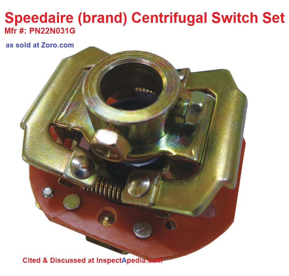
Electric motor start switch / centrifugal switch Speeds
A centrifugal switch connects the A/C electrical power to the motor to the start winding on the stator (and/or to the start capacitor) until the motor has reached a speed typically of 75-80% of its full run speed .
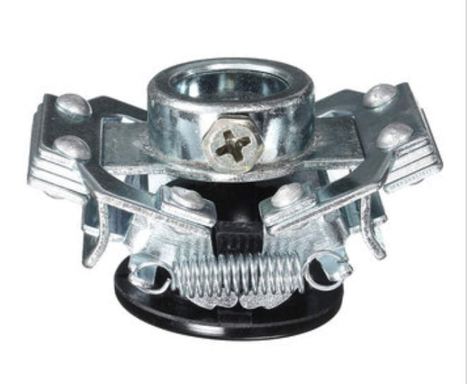
Centrifugal switches for electric motors like the switch shown above are sold with two to 6 poles and are specified as having specific-range of switch CUT-OUT (open or off) and CUT-IN (close or on) speeds.
For small electric motors like those used in most HVAC applications as well as in other small equipment that runs on 120VAC or 240VAC, the electric motor full speed is usually 1725 or 3450 rpm, though some equipment may use variable speed motors as well.
- High speed electric motor centrifugal switch open/close speeds:
A centrifugal switch like the ones shown at page top and at above-left will open ("throwout") or ("turn off the capacitor") at about 2800 rpm for a 3450 rpm electric motor.
In more detail: a centrifugal switch for a modern "high speed" electric motor rated at a running speed of 3450 rpm under full load might cut in or close (turn on the capacitor) from 1000-2000 rpm, and might open at speeds between 2600-3000 rpm. - Low-speed electric motor centrifugal switch open/close speeds:
The centrifugal switch will open (turn off the capacitor) at about 1400 rpm for a 1725 rpm electric motor and will be closed at speeds from 0 to about 1200 rpm [est].
...
Induction Motor Starting-Boost Design Options
In our more-detailed induction-type electric motor wiring diagram shown just below, the centrifugal switch, a model that is normally closed, opens at speed to cut both the start capacitor and the start winding from the motor's circuit.
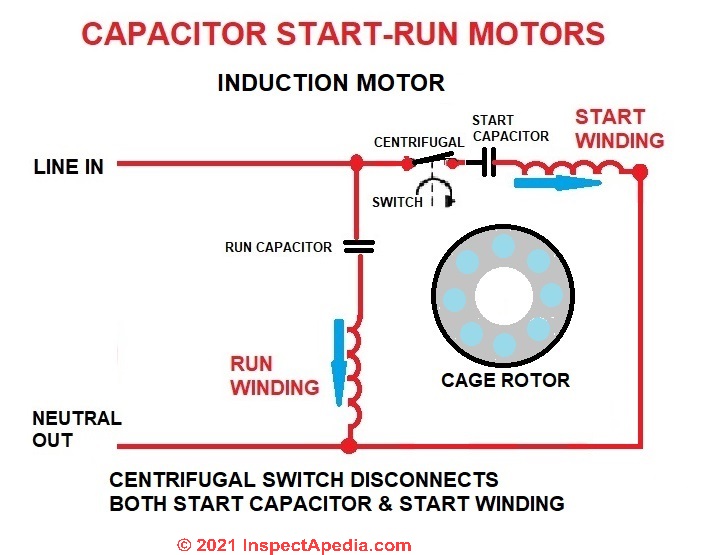
Watch out: If your electric motor uses this design an dif the centrifugal switch fails to operate the starting capactor will burn up or even explode and/or the start winding may overheat and be damaged.
Below our elecric motor drawing shows a different capacitor start/run design in which only the startign capacitor is cut from the circuit when the motor approaches run-speed. In this design the start winding remains energized as the motor continues to run.
At that point the start winding, or secondary winding, is functioning as an auxiliary winding helping smooth the motor's rotation.
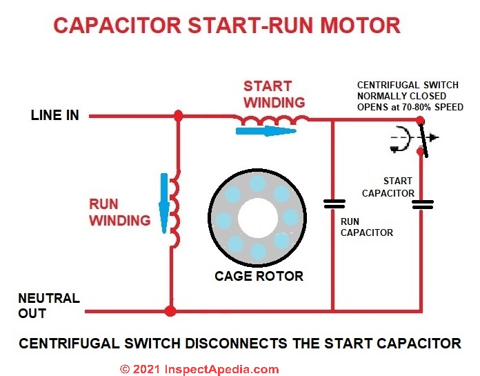
In this design if the centrifugal switch fails to open when it should (at higher motor speed) the starting capacitor will be destroyed.
...
What Happens if the Centrifugal Switch in an Electric Motor Fails?
Possible effects of a bad centrifugal switch include
- Electric motor never reaches its full run speed rpm - Switch opens before it should, motor stalls or struggles or overheats.
- Electric motor has trouble starting - If the centrifugal switch sticks in the closed position, the start capacitor will overheat. Special thanks to Paul J. Ste. Marie - 2015-01-10
- Electric motor makes unusual noises - Possibly switch chattering, motor balance or speed issues
- Electric motor runs backwards or sometimes but not always starts in the wrong spin direction - depending on the position of the motor when it last stopped.
Watch out: If the centrifugal switch is broken in the "switch-open" position, it will never connect the start capacitor to the motor's start winding, and the motor won't start and the main or "run" winding will overheat but may not fail.
Watch out: If the centrifugal switch is broken in the "switch-closed" position, it will keep the starting capacitor in the circuit and connected to the start winding continuously even after the motor has started.
The result is likely to be burnt-up motor start-windings or an exploded starting capacitor.
Why A start Capacitor Has to Drop out of the Circuit at 50% to 80% of BEMF
The centrifugal switch on a typical single-phase or split phase electric motor is designed to OPEN at 70-80% of the motor's full speed or per some sources 50-80% of the full speed rating for the motor.
Watch out: A "catastrophic capacitor failure" of a motor starting capacitor in which the start capacitor "explodes" or bursts can occur when the start capacitor remained engaged too long - perhaps because a centrifugal switch inside the motor did not disengage the starting cap circuit when it should-have.
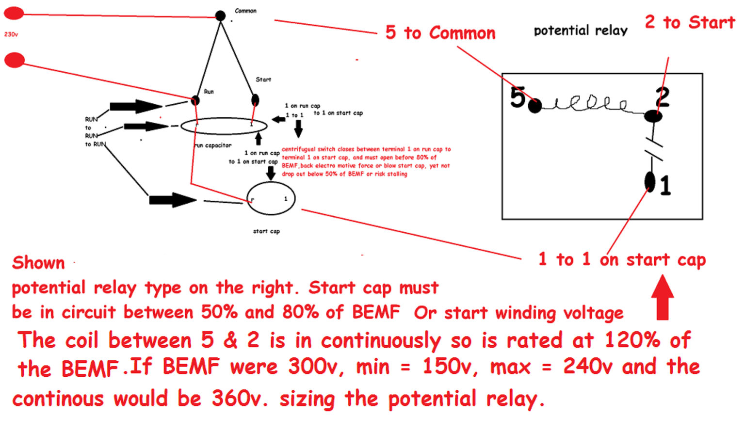
A Run capacitor 's terminals are wired to the Run and Start motor leads, the start capacitor also goes to the Run and Start leads but only briefly,
the Start capacitor must remain in the system for a minimum of 50% of the BEMF (back electro motive force) and not beyond 80% of the BEMF.
Should the Start capacitor drop out below 50% of BEMF the motor may stall, if the Start capacitor stays in beyond 80% of the BEMF you risk exploding the Start capacitor. - On 2019-07-24 by KD Grayson
...
Steps Diagnose & Repair the Electric Motor's Centrifugal Switch
If your electric motor uses a centrifugal switch to cut out the "start" capacitor once the motor is up to speed, a failure of that switch can cause motor failure.
A Speck of Debris Can Cause Centrifugal Switch Failure
Any little piece of dust can keep this switch from closing when the motor is stopped.
At this point, the motor just sits there and hums, not knowing which way to go or how to get started.
Simply knocking this one little dust particle off might make the repair, and the motor will run fine henceforth.
Most of the time you have to pull the back end of the motor off to get to this switch. - Courtesy of an InspectApedia.com reader
So start by making a visual inspection of the switch, normally at the rear or "bell housing" end of the motor.
Really? How do we do that if we don't even know where the centrifugal switch is found?
Where to Find the Centrifugal Switch in an Electric Motor
Check out the rear bell housing of the motor to see if the motor uses a centrifugal switch to switch the start / run capacitor or other windings in and out of the circuit at a specific RPM.
If a centrifugal switch is present, check that its switch contacts are not welded closed or contaminated with dirt and grease. The switch mechanism should can move freely. - WikiHow [36]
Not all motors use a start capacitor and centrifugal switch
Starting capacitors or electric motor starting capacitors (or motor start boosters) are often present on large single phase air conditioning compressors, as found on home air conditioning units, or on occasion on blower motors or even fan motors.
Electric motor starting capacitors are only very rarely present on small refrigeration compressors, such as those in refrigerators, and as far as we know, never present on 3-phase power systems.
We give more detail about failed electric motor starting capacitors, and we explain possible visual diagnosis of a failed starter capacitor (bulged ends) without having to perform electrical testing,
at HARD STARTING COMPRESSOR MOTORS.
Common Electric Motor Centrifugal Switch Defects
- Centrifugal switch contacts are dirt clogged - even a small bit of dust, oily-debris, or crud can cause trouble
- Centrifugal switch contacts don't move freely
- Arc burns on the centrifugal switch contacts
- Centrifugal switch contacts are welded together
- Motor runs backwards: if the centrifugal switch is sticking you can get random choice of run direction when the motor starts-up again.
Some electric motors use a potential relay instead of a centrifugal switch. If the pot. relay is bad the effect of random start direction could still occur. - The problem isn't the centrifugal switch but instead is a bad start or run capacitor
- The problem isn't the centrifugal switch but instead is a motor winding that shorts or opens as the motor's rotating speed increases
Motor Centrifugal Switch Diagnostic Tips
Thanks to a reader, Paul J. Ste. Marie we can add to the centrifugal switch diagnostic checkpoints above these comments and diagnostic tips:
A centrifugal switch as used in some electric motors uses the centrifugal or rotating force of the motor to open or close an electrical switch.
Electrical current applied to a start winding causes an electrical field placed at an angle to the field produced by the main or "run" winding to provide an initial rotating force to start the motor.
In these split-phase electric motors a centrifugal switch is used to switch off electrical power to the start winding once the motor has gotten up to a minimum speed of about 75% of its full run velocity. In essence the centrifugal switch turns off the start circuit and leaves the motor operating from its run-circuit alone.
This application of centrifugal switches is common in split-phase or "induction-start / induction-run alternating current (AC) electric motors that do not require a high starting torque, such as small power tools, grinders, etc. - citation. - Heinecke, Kevin (2015)
atReferences or Citations .
Ste.
Marie pointed out that
Another common reason for a CS or CSCR motor to fail to start is a bad centrifugal switch. If the switch contacts are dirty, the motor can fail to start.
If the switch freezes closed, the start capacitor will overheat. - P.S.M. 10 Jan 2015
Watch out: some damaged motor windings will test out just fine on the bench with the motor disconnected completely, but when the motor begins to spin a damaged wire in the winding may, due to the centrifugal force of rotation, open, causing the motor to run poorly or to stop completely or to chatter.
More detailed VOM tests on motor leads and windings are given in our diagnostic table found
at ELECTRIC MOTOR DIAGNOSTIC GUIDE
Is the Problem with the Motor Starting Capacitor or with the Centrifugal Switch in the Motor?
Without actually testing the motor start and run capacitor (or simply trying a new one) we can't be sure without more-extensive testing if the "motor won't run" problem is
- A failed starting capacitor
- A failed, damaged, shorted, burnt motor winding
- A failed centrifugal switch
We provide ELECTRIC MOTOR DIAGNOSTIC GUIDE - to help sort out these different causes of electric motor failure
Watch out: If the starting capacitor has failed the symptom is that the motor won't start. You may hear it humming or observe that it's getting hot. Turn the motor off right away If you observe this, in order to avoid damage while waiting for repairs.
...
Primary vs Secondary Electric Motor Windings
Most single phase electric motors have two sets of windings.
The main or primary windings are directly connected to the power lines while the motor in running. The second windings are usually thinner wires physically offset from the main windings inside the motor.
The purpose of the secondary windings is to provide directional information and an initial strong kick to get the motor started turning. Once the motor is started, the main or primary windings can keep the motor running just fine.
Methods of Controling Power to Secondary or Start Windings
Less common, these secondary windings are directly powered from the power lines through a run capacitor that provides a continuous time or phase shift to the windings.
Far more common, the secondary windings and capacitor are powered through a centrifugal switch that is closed for approximately 1/2 second on starting.
As the motor gets up to 2/3 speed, the centrifugal switch opens and disconnects the secondary windings.
This switch is usually behind and part of the connection plate where you attach the power cables in the end of the motor.
...
PTC-devices Can Drop the Start Capacitor from a Circuit
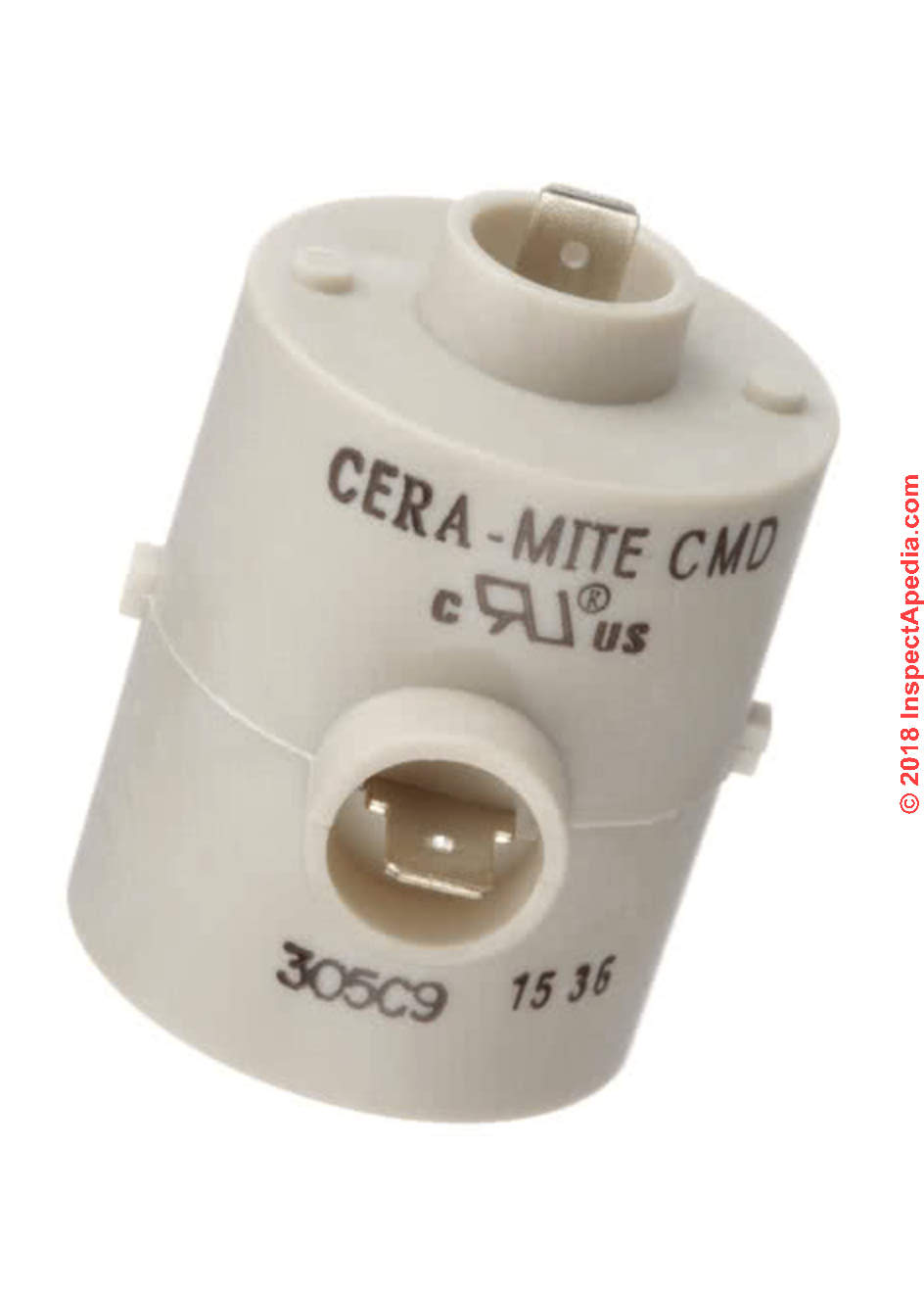
When a capacitor-start, induction-run electric motor such as is used on an air conditioner or heat pump must be hermetically sealed, we can't use a centrifugal switch. Instead we use one of the other devices described here: PTC devices, PRD relays, solid state starting relay, hot wire relays, or current relays.
Positive Temperature Coefficient devices are the traditional means of dropping the capacitor from the motor circuit once the motor has successfully started.
PTC devices are basically a thermistor-type device, using a tiny electric heater that use the change in electrical resistance of the heating element to open an electrical switch that removes the start winding in the motor from the run circuit. The switch opens in less than a second after the motor has started.
PTC devices have the advantage of being simple and avoiding the need for more complex electrical wiring of a motor starting system.
Supco explains that this device is unable to sense whether or not the motor has successfully started, and if the motor does not start, several minutes are needed to let the heater cool down before the motor restart can be attempted again.
This cool-down time provides a safety margin that helps protect against burning out the windings of a hard-starting motor.
...
PRD Potential Relay Device + Hard Start Capacitors Boost Starting Torque for HVAC Motors on TXV-based systems
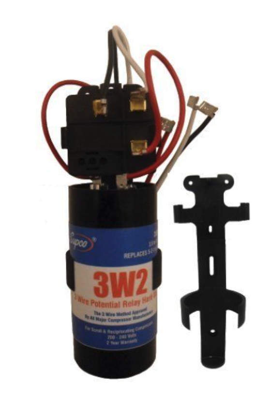
Potential Relay Devices use voltage sensing (The Supco method) or current sensing devices (two different approaches) to determine when to release the starting capacitor from the motor run circuit.
Supco points out that "The electronic potential relay is inherently more reliable and precise than the older type mechanical potential relay." [1]
Both of these start capacitor control approaches work fine, and typical HVAC or residential appliance motor repairs the technician won't need to consider which method is being used to control the capacitor as long as she/he follows the manufacturer's recommendations on the product for its selection and use.
SUPCO offers this explanation of why a potential relay hard start kit would be used:
Most single phase air conditioners and heat pumps use non-bleed thermostatic expansion valves (TXV’s or TEV's) to control refrigerant.
A problem with TXV’s occurs when a reciprocating compressor shuts off, refrigerant pressures don’t fully equalize. Pressures do equalize in scroll compressors; which, typically do not need hard start kits for this condition.
In a reciprocating compressor, the discharge pressure will drop to about 150 psig and the suction pressure will rise only to about 100 psig.
When the compressor tries to start, there’s too much load for the starting motor torque to overcome. This is especially true if the supply voltage is low. To increase starting torque, a start assist device can be used.
When a TXV is used, a potential relay hard start kit is employed. This will increase starting torque by a minimum of 300 % over using just a run capacitor.
... Systems with capillary tubes or fixed restrictors usually don’t need a full hard start kit, unless the compressor bearings are tight. In such cases, the compressor is probably near the end of its useful life anyway. - SUPCO Hard Starts booklet cited below.
The SUPCO booklet we cite below provides wiring connection details for 3-wire and 2-wire connected potential relay / hard start kits.
Hot Wire Starting Relay Devices
The following description of hot wire start relays and current relays is general and not technically exhaustive.
We welcome further comments or suggestions regarding these electric motor controls.
An alternative control, the hot wire relay, operates as both a start relay to releasae the start capacitor and/or start winding and also as an electrical overload or protection device. The hot wire relay works by making use of a resistive wire that causes a spring-loaded contact to open. During motor start-up high current flows through this relay and its resistive wire, causing the wire to expand. When sufficiently expanded, the wire opens a spring-loaded start-winding contact switch, disconnecting the winding from the circuit.
Current Relay Devices
A current relay is similar to the hot wire relay but rather than relying on temperature and an expanding wire to open the contacts of a switch, the current relay makes use of a magnetic field to open or close the device.
This is a NO or Normally-Open switch whose coil connected in series with the motor run-winding and whose contacts connect in series with the start winding.
With the switch open the start-winding is disconnected, when current is applied high current flows through the run-winding, producing a magnetic field in the coil that pulls the contacts closed to connect and operate the start winding.
Once the motor has begun spinning the run-winding current is reduced, the switch then opens and the start winding is disconnected. But as the motor is now running the current flow is reduced so the switch remains in its NO position.
...
...
Continue reading at ELECTRIC MOTOR DIAGNOSTIC GUIDE - home, or select a topic from the closely-related articles below, or see the complete ARTICLE INDEX.
Or see ELECTRIC MOTOR CENTRIFUGAL SWITCH or PTC PRD FAQs, diagnostic questions & answers posted originally at this page.
Or see these
Recommended Articles
- BASIC ELECTRICAL TESTS for BURNED OUT COMPRESSOR MOTORS
- CAPACITOR TYPES, for MOTORS
- CAPACITORS for HARD STARTING MOTORS
- CAUSES of HARD STARTING ELECTRIC MOTORS
- CAPACITOR SIZE DETERMINATION for ELECTRIC MOTORS
- COPELAND ELECTRICAL HANDBOOK [PDF]
- HARD STARTING COMPRESSOR MOTORS
- HOW a STARTING CAPACITOR WORKS
- HOW to TEST the MOTOR to ID TERMINALS
- LOCATE the STARTING CAPACITOR
- MOTOR CAPACITOR WIRING GUIDE
- STARTING CAPACITOR SAFETY
- TEST a MOTOR START or RUN CAPACITOR
- ELECTRIC MOTOR CENTRIFUGAL SWITCH or PTC PRD
- ELECTRIC MOTOR DIAGNOSTIC GUIDE - home
- ELECTRIC MOTOR HORSEPOWER & CIRCUIT WIRE SIZE
- ELECTRIC MOTOR OVERLOAD RESET SWITCH
- ELECTRIC MOTOR RUN DIRECTION
- ELECTRIC MOTOR WIRING DIAGRAMS & GUIDES
- HARD STARTING ELECTRIC MOTOR CAUSES
- HUMMING MOTOR SOUNDS
Suggested citation for this web page
ELECTRIC MOTOR CENTRIFUGAL SWITCH or PTC PRD at InspectApedia.com - online encyclopedia of building & environmental inspection, testing, diagnosis, repair, & problem prevention advice.
Or see this
INDEX to RELATED ARTICLES: ARTICLE INDEX to ELECTRICAL INSPECTION & TESTING
Or use the SEARCH BOX found below to Ask a Question or Search InspectApedia
Ask a Question or Search InspectApedia
Share this article:Try the search box just below, or if you prefer, post a question or comment in the Comments box below and we will respond promptly.
Search the InspectApedia website
Note: appearance of your Comment below may be delayed: if your comment contains an image, photograph, web link, or text that looks to the software as if it might be a web link, your posting will appear after it has been approved by a moderator. Apologies for the delay.
Only one image can be added per comment but you can post as many comments, and therefore images, as you like.
You will not receive a notification when a response to your question has been posted.
Please bookmark this page to make it easy for you to check back for our response.
IF above you see "Comment Form is loading comments..." then COMMENT BOX - countable.ca / bawkbox.com IS NOT WORKING.
In any case you are welcome to send an email directly to us at InspectApedia.com at editor@inspectApedia.com
We'll reply to you directly. Please help us help you by noting, in your email, the URL of the InspectApedia page where you wanted to comment.
Citations & Reviewers
In addition to any citations in the article above, a full list is available on request.
- Heinecke,Kevin, "Leeson Electric Motors, Gearmotors and Drives, Reference Article", LEESON Electric Corporation 1051 Cheyenne Avenue Grafton, WI 53024-0241, un-dated, retrieved 10 Jan 2015, original source: http://www.leeson.com/TechnicalInformation/sphase.html
- COPELAND ELECTRICAL HANDBOOK [PDF] free download from Emerson Climate Controls, at InspectApedia.com
- [3] "Kenmore model 580. 75121 room unit air conditioner wiring diagram [PDF] Sears Roebuck window air conditioner wiring diagram for a typical room or window air conditioner
- George Fazio, reader, contributed comments on failed starter capacitor diagnosis by noting the bulged capacitor ends. 09/25/2009
- Industrial Electronics, ELECTRICAL PRINCIPLES GUIDE: AC SINGLE-PHASE MOTORS [PDF] retrieved 2021/11/30, original source: http://www.industrial-electronics.com/electric_prin_2e_19.html
We attempted to obtain contact information for this company but their home page does not identify authors nor could we find contact information. - SUPCO AC Hard Starts, HARD START CAPACITOR BOOKLET [PDF], SUPCO, Sealed Unit Parts Co., Inc., PO Box 21, 2230 Landmark Place, Allenwood NJ 08720 USA, Tel: 732-223-6644, Website: www.supco.com, Email: info@supco.com retrieved 2018/07/11, original source: http://www.mcaair.com/docs/supco/hardstartbooklet.pdf
- Supco, Sealed Unit Parts Company [Website] PO Box 21, 2230 Landmark Place, Allenwood, New Jersey, 08720, Tel: 732-223-6644, 201-449-3300, email: info@supco.com, provided the compressor starting capacitor and packaging information (purchased by the author from an air conditioning parts supplier in New York)
- our example uses a Sealed Unit Parts Company Solid State part No. RSC 10 115V starting capacitor which was designed for installation on refrigerators and freezers. See www.supco.com/ - In addition to citations & references found in this article, see the research citations given at the end of the related articles found at our suggested
CONTINUE READING or RECOMMENDED ARTICLES.
- Carson, Dunlop & Associates Ltd., 120 Carlton Street Suite 407, Toronto ON M5A 4K2. Tel: (416) 964-9415 1-800-268-7070 Email: info@carsondunlop.com. Alan Carson is a past president of ASHI, the American Society of Home Inspectors.
Thanks to Alan Carson and Bob Dunlop, for permission for InspectAPedia to use text excerpts from The HOME REFERENCE BOOK - the Encyclopedia of Homes and to use illustrations from The ILLUSTRATED HOME .
Carson Dunlop Associates provides extensive home inspection education and report writing material. In gratitude we provide links to tsome Carson Dunlop Associates products and services.
 |
HOME | ABOUT | ASK a QUESTION | CONTACT | CONTENT USE POLICY | DESCRIPTION | POLICIES | PRIVACY | |
| © 2026 - 1985 Publisher InspectApedia.com - Daniel Friedman | |||||||||