
InspectAPedia® FREE Encyclopedia of Building & Environmental Construction, Diagnosis, Maintenance & Repair |
Question? Just ask us! InspectAPedia
|
 Air Volume Controls AVCs for Water Tanks
Find & Repair the Water Tank Air Volume Control Device
- POST a QUESTION or COMMENT about air volume controls on water tanks: how they work, why they are needed, and how to fix, repair, replace, or abandon an AVC that is not working, hissing, leaking, or just generally making trouble.
Guide to air volume controls on water tanks:
This article describes water tank air volume controls (AVCs) used to keep a proper air charge in a water pressure tank and thus avoid well pump turning on and off to frequently.
We describe what AVCs look like, we explain the types of air volume controls used on jet pumps and on submersible pumps, and we describe where to find them, and how these devices work, and how they can be repaired, replaced or just abandoned.
InspectAPedia tolerates no conflicts of interest. We have no relationship with advertisers, products, or services discussed at this website.
- Daniel Friedman, Publisher/Editor/Author - See WHO ARE WE?
Water Tank AVCs Air Volume Controls - Defined, How they Work, How to Use
 In water pressure tanks that do not use an internal bladder, over time, the air in the tank will
be absorbed into the water and the tank will become ‘waterlogged’. This means that the tank is full or nearly full of water.
In water pressure tanks that do not use an internal bladder, over time, the air in the tank will
be absorbed into the water and the tank will become ‘waterlogged’. This means that the tank is full or nearly full of water.
The pump will come on and off very quickly (short cycling or rapid cycling water pump).
This short cycling is hard on the pump, and air is added to the tank to correct the situation. - Adapted with permission from Carson Dunlop Associates Home Reference Book.
Article Series Contents
[Click to enlarge any image]
- AIR VOLUME CONTROLS ROUND/Tube - jet pump system AVCs
- AIR VOLUME CONTROLS RECTANGULAR - US Gauge & Similar Type 310WJ, Type 300SL, or Type 6 Rectangular AVCs vent excess air
- AIR VOLUME CONTROLS FLOAT TYPE
- AIR VOLUME CONTROLS on DRAIN BACK SYSTEMS
- AIR VOLUME CONTROL TEST
- AIR VOLUME CONTROL ADJUSTMENT
- AIR VOLUME CONTROL REPAIR
- AIR VOLUME CONTROLS, HISSING
- AIR VOLUME CONTROLS, REPLACE
- AIR VOLUME CONTROLS, GET RID OF
- MICRONIZER AIR VOLUME CONTROL - on WellMate well tanks
The job of the AVC is to keep air in the water tank to avoid waterlogged water tanks or well pump short cycling.
The air volume control or "AVC" device mounted (usually) on older steel water tanks (ones that do not use an internal bladder to keep water and air separate) is designed to automatically add air to the water pressure tank when it's needed.
If a water tank loses its air charge it stops working properly and usually results in the water pump turning on and off rapidly - "short cycling" of the water pump. This condition, in turn, can damage or even burn up the water pump.
Round Air Volume Control Devices With Copper Tube
An "automatic" air volume control (AVC) device may be installed on the water pressure tank if it's an older, bladderless steel tank.
The AVC is intended to automatically put a little bit of replacement air into the tank from time to time as water pressure cycles up and down, that is, each time that the water pump runs.
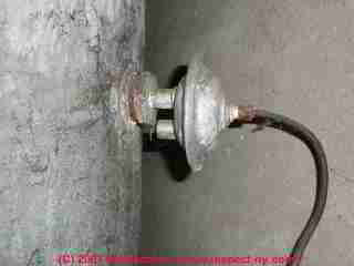
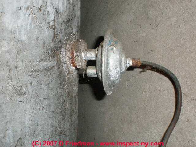
If you see a round steel disc of about 4" diameter and about 1" thick on the water tank, mounted perhaps at the middle of the tank height or at the water outlet to the tank, or perhaps on the side of the tank with a plastic or copper tube connecting the disc to a fitting on the tank or nearby piping, this is the AVC..
Used on jet pump water supply systems, on each pump "on" cycle the AVC draws in a small volume of air that is then pushed onwards into the water pressure tank.
The tube connecting the AVC to the pumping chamber suction side provides the pressure drop that pulls on a diaphragm on the AVC that in turn causes the AVC to draw in its air charge.
The air volume control might be found on the side of the water tank (above left) and is typically connected to the water pump itself (above right) by a flexible copper tube.
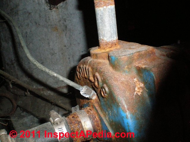
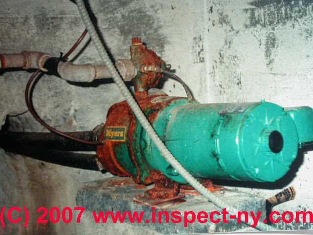
The AVC may also be located right on top of a one line or two line jet pump such as is visible at the top center in our Meyers™ well pump photo at left.
US Gauge & Similar Type 310WJ, Type 300SL, or Type 6 Rectangular Air Volume Controls = Excess Air Vents
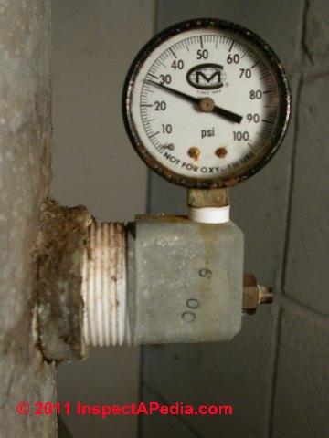
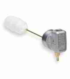
The alternative air volume control shown here does not include a disc-shaped device and has no connection to the water system's pump or other piping.
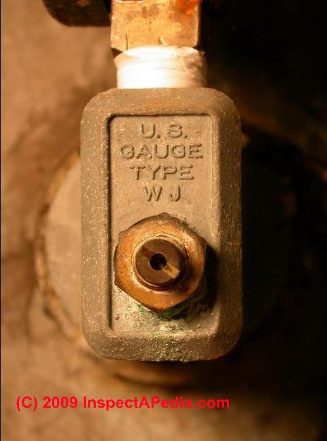
The hole seen in the end of the brass screw is the air inlet for this air volume control.
The deep-well AVC below does not use copper tubing, all it's parts are self-contained. This is a valve that you may hear hissing if it's working.
- The U.S. Gauge Type 300L or US Gauge Type 6 AVC is intended for use on shallow wells. Note the tubing fitting on the bottom of the valve.
This part includes a tapping to accept a water pressure gauge. The AVC is designed to work in conjunction with an air inlet valve such as a Schrader valve[6] or a Dill type valve[5] mounted in the hose connection. - The US Gauge Type WJ or US Gauge Type 310WJ (for deep wells) Air Volume Control produced by U.S. Gauge, also located under the Ametek® brand are intended for deep wells using submersible well pumps.
Watch out: As we discuss
at SNIFTER VALVES below,
in general these air volume control valves function only to release excess air in the water pressure tank;
in that case air is obtained from other components (such as the snifter valve). They let air out. Air is let into the system using a separate device, usually a snifter valve discussed below.
At WATER TANK AIR VOLUME CONTROL DIAGNOSTIC FAQs we provide more details (and photos) explaining the difference between the US Gauge Type 300L or Type 6 AVC and the US Gauge Type WJ or Type 310WJ air volume control.
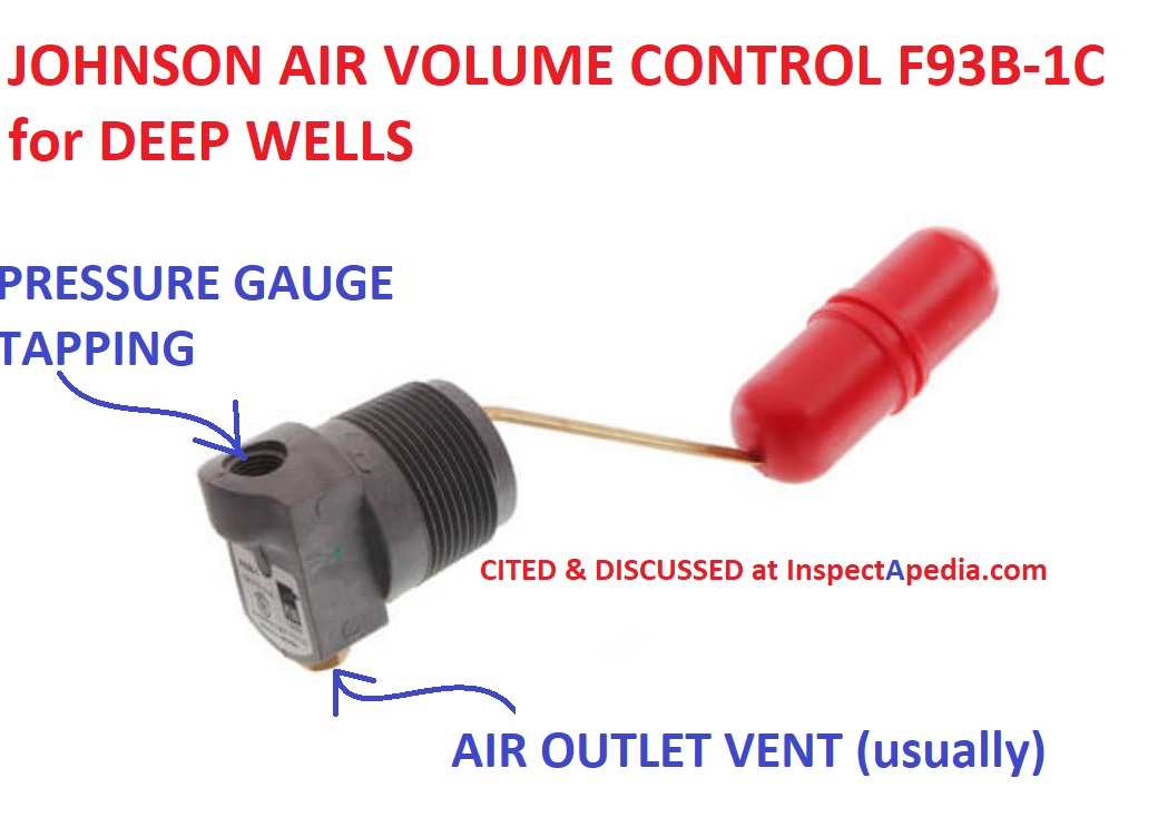
How does a US Gauge Type WJ or similar air volume control work? Drainback air volume control.
Using a US Gauge Type WJ or similar air volume control to manage air in the water pressure tank is a different approach that is unfamiliar to so many homeowners that we've seen some odd advice like "take off the part and throw it away" - which is usually not a good idea.
The air volume control approach used with these valves is also called a drainback system. When water level falls inside the pressure tank to a level below the valve and its float, the valve opens, bleeding excess air out of the pressure tank.
Separately, a snifter valve (see below in this article) in the well piping (usually hidden inside the well) is the device that forces air into the water piping from the well and thus into the pressure tank at each pump on-cycle.
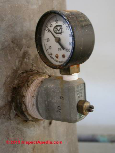
Our photo (below left and right) shows a U.S. Gauge Type WJ - so we know this installation is for a deep well.
As U.S. Gauge points out,
U.S. Gauge Air Volume Controls are designed for domestic water supply systems which deliver a quantity of air to the pressure tank with each cycle of pump operation.
Insufficient air in the pressure tank causes frequent operation of the pump.
Too much air in the pressure tank will permit large bubbles to be carried into the piping system. This causes a disagreeable noise and sputtering at the faucets.
It is the function of U.S. Gauge air volume controls to maintain the correct relationship between the volume of air and the quantity of water in the pressure tank.
As we illustrate below, this air volume control device uses a float that moves as the water level inside the water tank changes. The float movement allows air into or out of the water pressure tank as needed.
Adjustment of the US Gauge type WJ AVCs is in a separate article found
At DRAIN BACK / SNIFTER VALVE TROUBLESHOOTING we detail how the AVC is tested on a drain-back system or bleed-back system is tested to see if it is in fact releasing excess air as it should.
An excerpt is given just below
at AIR VOLUME CONTROLS on DRAIN BACK SYSTEMS
Drain-Back Water System Air Volume Control Valves

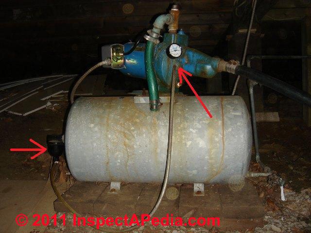
Air Volume Control Valves on drain-back pump and water systems are one component of a three-part system designed to protect well or lake water supply pipes from freezing and to maintain the air charge in a water pressure tank on some submersible pump systems where a bladderless water tank is installed.
A snifter valve is installed at a check valve at the water tank (photo at left) and works with a drain-back valve located in the well or lake below the frost line to insert air into the water piping system for freeze protection.
Because the snifter valve & drain back valve will result in a large charge of air pushed back up the water piping and into the water tank at each water pump on-cycle, the air volume control used on the pressure tank must release the excess air to avoid over-charging the water tank with air.
At DRAIN BACK / SNIFTER VALVE TROUBLESHOOTING we detail how these drain-back system or bleed-back system components are tested, including the AVC on the water pressure tank.
An excerpt is just below:
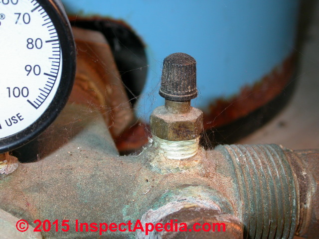
If the air volume control is working on a drain-back system you will at least occasionally hear air hissing out of the excess air release port on the AVC (blue arrow in the photo at below left).
If the air volume control is not working on a drain-back system, because each pump on cycle is pushing a lot of air into the water tank you will ultimately see air spurting out of the building's plumbing fixtures such as faucets. That's because the AVC is not releasing the excess air in the system.
See AIR DISCHARGE at FAUCETS, FIXTURES
If the AVC is not working properly on a non drain-down water systems you will find the opposite problem: a water-logged pressure tank causing well pump is short cycling.
Watch out: short cycling can still occur on a drain-down (bleed-back) system too, but not because the AVC isn't working.
Rather, if the snifter valve stops admitting air into the piping system OR if the drain-down valve becomes clogged and stops draining water out of the water piping, then because air isn't entering the piping no air is being pushed back up into the bladderless pressure when the pump runs.
Eventually the water tank will become water logged and the well pump or lake pump will cycle on and off rapidly when water is run in the building.
Watch out: On a drain-down / bleed-back water system with either of these two problems, because the well piping is not able to drain and not able to fill itself with air at the end of each pump-on cycle, there is also a risk of frozen well or lake water piping.
If your drain-down system pump is short cycling and your water piping between well (or lake) and the water tank is not buried below the frost line, you may find you have two problems: you had a warning of trouble when the well pump was short cycling, and now you've got frozen pipes too.
Watch out: if on a submersible well pump system that uses a snifter valve for air volume control you later convert a bladderless water pressure tank to a tank using an internal bladder, you should remember to remove both the snifter valve located on the check valve near the water pressure tank and the bleeder orifice or drain-back valve located on the well piping.
See SNIFTER & DRAIN BACK VALVES for a complete discussion of drain back systems, snifter valves, drain back valves and their related components.
Definition of Schrader Valves, Brady Valves & Dill Valves
Definition: Schrader valves (American Valves) and Dill Valves are used principally on vehicle tires to insert (or release) air to a specified pressure.
The valves are also used, often in modified form with an internal spring with strength matched to the application where air inlet or outlet or water or air pressure management require adjustment on water pressure tanks and similar systems.
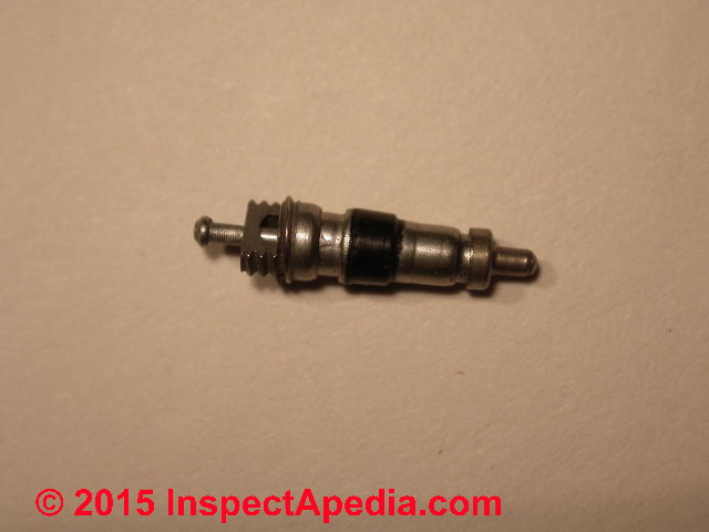
The Schrader valve, Brady Valve, Dill valve ( different companies) consists of an externally and internally threaded metal stem.
The external valve base and stem connect (using appropriate seals or washers) to the vehicle wheel rim, or in plumbing to a water pressure tank or water piping at an appropriate location.
The internal stem of the valve accepts a replaceable part, the actual control valve that opens (when a center pin is pressed) to admit air or to release air. In reverse, pressure inside the system pushing against the valve stem core closes the valve when its center pin is not depressed. [5][6]
Similar control valves but of different diameters are used in other countries than those comprising North America.
An example of a special class of these air valves is the snifter valve discussed just above and used on drain-down water systems. This valve includes a low-pressure valve stem core that will open to admit air into the valve at about 10 psi. Special versions of snifter valves can operate with as little as 5 psi.
Details are at SNIFTER & DRAIN BACK VALVES
A different range of air inlet valve is used at other (non-drain-down) water systems at the water pressure tank to add or adjust the air charge in the pressure tank. Photos of a typical air inlet valve located at a water tank tee is shown above along with a typical valve stem core. These may be found on both bladderless and internal-bladder type water tanks.
Watch out: when replacing an air inlet valve stem core be sure to select a valve core whose opening pressure (to admit air) is properly-matched to the application. Installing an automotive tire valve stem core into the stem of a snifter valve will make you sorry.
See WATER TANK AIR INLET VALVE
and WATER TANK AIR VALVE REPAIRS
Other Air Volume Controls on Large Water Storage Tanks
On some water storage tanks such as the antique 450-gallon tank shown at left (courtesy of reader Craig Revill), the air volume control may not be so obvious (photo below right).
The device shown is (we should say "was") an air volume control produced by Penn Electric Switch Co., Des Moines Iowa.
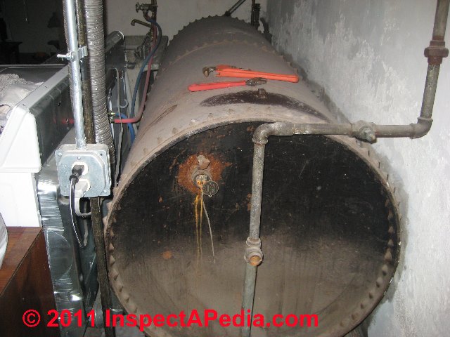
You could guess at the function of this device even if the manufacturer hadn't generously given an identification tag: notice the small diameter brass tube connecting the water tank to the well pump.
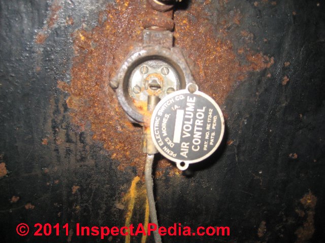
The patent for this air volume control switch was published in 1943 and patented by Burton E. Shaw. At left we illustrate (from the patent application) just how this air volume control switch worked.

Here is the air volume control patent text [PDF] and an explanation of how this AVC worked.
Shaw explained this air volume control or AVC was intended as a deep well device - by this he probably meant not shallow or "dug" wells.
The device was intended to be mounted in the wall of a water storage tank (as above) and adjacent to the water level in the tank so that the valve could respond to both air pressure and the water level in the tank itself.
The valve relieved air from the tank when the water level was low as a result of excess air from the pneumatic head of the tank, but it would prevent the release of air from the tank when the working pressure inside the tank was below the required amount.
Test Air-Volume Controls (AVCs) on Water Tanks
Details about how to inspect & test the AVC to determine if it is working to keep a proper air charge in the water tank are
Excerpts are below.
If the air volume control valve is working properly, it uses the pressure changes caused by the cycling on and off of the water pump to automatically add air to the water tank when it's needed.
If the air charge in your water pressure tank is not being maintained, either there is a leak in the tank or the AVC is not working. Usually the case is the latter.
If an auto-venting AVC is installed (a type that expels excess air charge in the water tank) and if the AVC is working you will occasionally hear air hissing out of the fitting, as we discuss
at AIR VOLUME CONTROLS, HISSING .
Adjusting a US Gauge Type WJ Air Volume Control
Details about AVC or air volume control adjustment are now
at AIR VOLUME CONTROL ADJUSTMENT
Note: On a water tank that uses an internal bladder (keeping water and air separated), the air charge is not normally lost and the air volume does not normally need adjustment.
How to Repair a Leaky US Gauge Type WJ or Type 300L Drainback System or Snifter Valve System Pressure Tank Air Volume Control
Our complete article about repair procedures for AVCs - Air Volume Controls - is now
at WATER TANK AIR VOLUME CONTROL REPAIR . An excerpt is below.
- Leaks at the valve mount: this is a standard plumbing problem. If your pressure tank or the valve mount tapping threads are not badly corroded, remove the valve, clean all threads, reassemble using pipe sealant or teflon tape.
- Leaks at the Type WJ adjustment screw: you may be able to disassemble, clean the tapping, and replace the existing parts. Replacement parts are available from US Gauge at AMTEK [2] The company sells a Type 310 valve assembly, Spec No. 085043A
- US Gauge Type 310 WJ not working: AMTEK sells Type 310 valve seat replacements, Spec No. 085392A.
- US Gauge Type 6 or Type 300L Shallow Well AVC not working: contact the company's customer service line 727-536-7831 to ask about spare parts.
- Air leaks or hissing at the AVC are discussed
at AIR VOLUME CONTROLS, HISSING
Recapping, both types of these air volume controls are used only on bladderless water pressure tanks - tanks that do not use an internal bladder.
This control is used on shallow wells and jet pumps.me controls are
at AIR VOLUME CONTROLS, HISSING
Replace an Air Volume Control Valve
Details about replacement options for AVCs are now found
at AIR VOLUME CONTROLS, REPLACE . Excerpts are below.
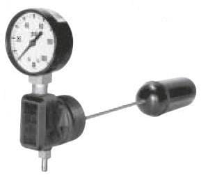
U.S. Gauge makes rectangular type AVCs, as we illustrate above. So do some other companies.
Watch out: rectangular AVCs like the U.S. Gauge AVC + Gauge unit illustrated here from the company's product literature, incorporates a float inside the water tank. If you look closely at our photos you 'll see that the gauge mounts through a 1 1/4" diameter ANPT threaded pipe connection into the water tank.
Watch out: also to be sure to order the proper air volume control model. For example the U.S. Gauge AVC Type 300L is designed for shallow well operation, and the U.S. Gauge Type 310WJ Air Volume Control is designed for deep well operation.
These devices do not work in an identical fashion, so buying the wrong model for your well would be a mistake.
Eliminate the Air Volume Control Valve
Details about getting rid of the AVC as well as some advice about making that change a success are
at AIR VOLUME CONTROLS, GET RID OF
If you convert from a non-bladder type water pressure tank to a water tank using an internal bladder, part of that installation will include the removal of any air volume control valves on the system, including an AVC that may be mounted on the well pump (above-ground jet pumps) or a hidden AVC that is found inside the well piping (submersible well pumps only).
Question: Why Can't I Find the Air Volume Control on My Water Pump or Water Tank?
I've looked all over my water pressure tank for that round disk thingie that you show in the photos in this AVC article but I just can't find it, nor do I see that rectangular version that is sometimes on the tank side. Where is it?
Reply: your well water system may not have an AVC, or the AVC may be hidden on the well piping inside the well
Bladder type water tanks do not use an air volume control valve: Air volume control valves are present only on steel water tanks which do not include an internal bladder to keep water and air separated inside the water tank.
In other words, if your water tank is one of the newer models which uses an internal bladder, you won't find an AVC installed.
See details at WATER TANK BLADDERS & CAPTIVE AIR
A bladder-type water tank keeps the air charge separated from the water. The air is in the tank and the water is inside the bladder inside the tank. Thus the air charge does not become lost by absorption into the water.
Hidden AVCs that may be found inside the well are discussed
at AIR VOLUME CONTROL VALVES INSIDE the WELL
Air Volume Control Manuals, Sources, References
- [1] U.S. Gauge Special Application Gauges: Type 300L and 310WJ Air Volume Controls, product description, 2002, Ametek® Inc, U.S. Gauge, 820 Pennsylvania Blvd., Feasterville PA 19053, USA, Tel: 215-355-6900 www.ametekusg.com Customer Service: 863-534-1504, web search 03/23/2011, original source: http://www.jlwinstruments.com/PDF_files/D17_MODEL300-310.PDF Sadly this URL now reroutes to a dead end
- [2] AMTEK, 900 Clymer Avenue 8600 Somerset Drive Sellersville, PA 18960 U.S.A. or Customer Service at
- [5] Dill Air Controls Products, 1500 Williamsboro St., PO Box 159, Oxford, NC 27565, Tel: (919) 692‐2300, Website: http://dillaircontrols.comAMTEK, Largo, FL 33773 U.S.A.Sales/Technical Support: 215-257-6531, Customer Service: 727-536-7831, Website: www.amtekusg.com, Email US Gauge at usg.sales@ametek.com.
- [3] Flosource.com/ provides links to some US Gauge air volume control products installation and adjustment
- Flotec STANDARD EPOXY LINED TANK INSTALLATION INSTRUCTIONS [PDF] (1999) Flotec, PO Box 342, Delavan WI 53115 USA Tel: 1-800-365-6832, Email: flotec@flotecpump.com Website: www.flotecwater.com
- Johnson Controls F93 SERIES AIR VOLUME CONTROL INSTALLATION INSTRUCTIONS [PDF] (2018)
- Johnson Controls, F92, F93 SERIES AIR VOLUME CONTROLS FOR DEEP WELL, SHALLOW WELL AND SUBMERSIBLE PUMPS [PDF], Johnson Controls, Controls Group 507 E. Michigan Street P.O. Box 423 . Milwaukee, WI 53202 USA, retrieved 2019/01/30, original source: http://vikingcontrols.com/_documents/product/125250.PDF
- Johnson Controls, F92 SERIES AIR VOLUME CONTROLS for SHALLOW WELLS [PDF] (2015), Op. Cit., https://cgproducts.johnsoncontrols.com/CAT_PDF/1922350.PDF
- Johnson Controls F93 SERIES AIR VOLUME CONTROL TECHNICAL DATA [PDF] (2020)
- Johnson Controls, F93 Series Air Volume CONTROLS for DEEP WELLS [PDF] Product/Technical Bulletin, Op. Cit., retrieved 2019/01/30 original source: https://cgproducts.johnsoncontrols.com/MET_PDF/2476643000.pdf
- Smart Tank, Installation Instructions, Flexcon Industries, 300 Pond St., Randolph MA 02368, www.flexconind.com, Tel: 800-527-0030 - web search 07/24/2010, original source: http://www.flexconind.com/pdf/st_install.pdf [Copy on file as /water/Smart_Tank_Flexcon.pdf ]
- MORRISON WELL SYSTEM FUNCTION & REPAIR - special piping to avoid frozen well water systems
- SNIFTER & DRAIN BACK VALVES
...
Reader Comments, Questions & Answers About The Article Above
Below you will find questions and answers previously posted on this page at its page bottom reader comment box.
Reader Q&A - also see RECOMMENDED ARTICLES & FAQs
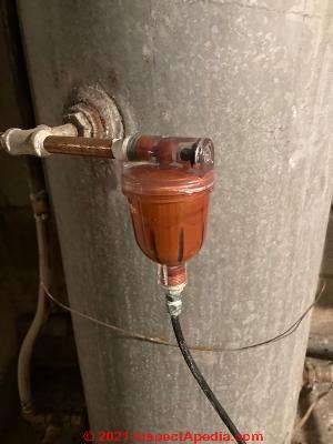
On 2021-12-04 by Inspectapedia Com Moderator (mod) - Identify this water pump/tank control device: AVC? Ping Pong Ball?
 @DANIEL MINTZ,
Thank you for the photo and pump control question.
Typically a small diameter tube somewhere on your water supply system conducts system pressure to the sensor port on the bottom of a pump pressure control switch - that pressure is what tells the switch to close or turn ON the pump (the CUT-IN pressure typically at 20 or 30 psi) and also when to turn the pump OFF (the CUT-OUT pressure, typically 40-50 psi) .
On water pump and tank systems that use a bladderless water pressure tank, there is often a second control intended to maintain the air charge in the tank. That control may in some (not all) installations, use a second pipe or tube between the water pump and the tank.
Your photo is great but it'd be helpful to see another photo that shows us the water pump and a third photo that shows all of the pump's pipe and tubing and control connections. You can post one photo per comment but as many comments as needed.
While I don't see a ping pong ball in your photo I do see a reddish-orange device attached to a small diameter copper tube and to a tee at about the mid line of a galvanized iron (bladderless) water pressure tank.
I think that device is a type of air volume control valve or AVC that is designed to inject some air into the pressure tank when the water pump cycles on and off. The job of the AVC is to keep sufficient air in the pressure tank as to prevent the pump from short-cycling on and off too frequently - a problem that occurs if the air charge is lost.
If water were actually flowing through it onwards to building fixtures it'd look like a filter but in that location I am guessing AVC.
Please see
https://inspectapedia.com/water/Water_Tank_Air_Volume_Controls.php WATER TANK AIR VOLUME CONTROLS
where we will copy your question and photo so as to help out or to invite helpful comment from other readers who need to understand air volume controls on water tanks.
Water tanks like yours are discussed
at WATER TANK STEEL
On 2021-12-04 by DANIEL MINTZ
From my Goulds pump to the pressure control switch there is one tube which breaks the circuit and turns off pump when pressure gets high enough to push contacts apart.
But there is also a second tube, from pump to pictured ping pong ball. Does this somehow release the pressure in the first tube when difference between tank pressure and pump reaches 20? Or does it serve some other function?
[Photo above]
This Q&A were posted originally
at WATER PUMP PRESSURE SWITCH INSTALL / REPLACE
On 2020-04-10 by Rahn
Thank you for your help!!
On 2020-04-09 by (mod)
Rahn
A shallow-well pump and tank system ought to be able to convert to a bladder-type pressure tank with no problem.
Yes you can simply find a small pipe plug of the right size and threads - in North America that's standard pipe thread or NPT, usually in 1/8" or perhaps 1/4" size to plug the old pressure line between water pump and water pressure tank.
Your new bladder type tank won't have a tapping for an AVC (Air Volume Control).
Watch out: That simple tank swap-in is NOT true for deep well submersible pump systems that use a snifter valve - for readers with that type of system, before changing your pressure tank type take a look at
On 2020-04-09 by Rahn
Great article, thanks for posting. I currently have an old steel pressure tank with my Flotec shallow well pump and the small line running from the pump to AVC and then plumbed into the side of the tank.
The question I have is that I am thinking of replacing the old steel tank with a new pre-charged tank. Can I just replace the line that goes to the current AVC with a plug at the pump housing? Just wanted to verify that I could plug the port on the pump and not cause any issues. Thanks!
On 2019-04-06 by (mod) - Will The air volume control valve stop your pump from building pressure even though it’s running?
No, Lonny.
On 2019-04-06 by Lonny
Will The air volume control valve stop your pump from building pressure even though it’s running
On 2019-01-08 by (mod)
That sounds like a conventional air pressure adjustment fitting and what you've done should be perfectly fine without any further modification
...
Continue reading WATER TANK AIR VOLUME CONTROL REPAIR or select a topic from the closely-related articles below, or see the complete ARTICLE INDEX .
Or see WATER TANK AIR VOLUME CONTROL DIAGNOSTIC FAQs - questions & answers posted originally on this page
Or see these
Recommended Articles
- AIR VOLUME CONTROLS, WATER TANK
- AIR VOLUME CONTROL TEST
- AIR VOLUME CONTROL ADJUSTMENT
- AIR VOLUME CONTROL REPAIR
- AIR VOLUME CONTROLS, HISSING
- AIR VOLUME CONTROLS, REPLACE
- AIR VOLUME CONTROLS, GET RID OF
- MORRISON WELL SYSTEM FUNCTION & REPAIR
- WATER PUMP SHORT CYCLING
- WATER PUMP SWITCH INSTALLATION MANUALS
- WATER PUMP & TANK I&O & REPAIR MANUALS
- WATER TANK AIR, HOW TO ADD
- WATER TANK AIR VOLUME CONTROLS
- AIR VOLUME CONTROL ADJUSTMENT
- AIR VOLUME CONTROLS on DRAIN BACK SYSTEMS
- AIR VOLUME CONTROLS ROUND/Tube
- AIR VOLUME CONTROLS RECTANGULAR
- AIR VOLUME CONTROLS FLOAT TYPE
- AIR VOLUME CONTROLS, GET RID OF
- AIR VOLUME CONTROLS, HISSING
- AIR VOLUME CONTROL REPAIR
- AIR VOLUME CONTROLS, REPLACE
- AIR VOLUME CONTROL TEST
- SNIFTER & DRAIN BACK VALVES
- WATER TANK DIAGNOSIS & REPAIR - home
Suggested citation for this web page
WATER TANK AIR VOLUME CONTROLS at InspectApedia.com - online encyclopedia of building & environmental inspection, testing, diagnosis, repair, & problem prevention advice.
Or see this
INDEX to RELATED ARTICLES: ARTICLE INDEX to WATER SUPPLY, PUMPS TANKS WELLS & SPRINGS
Or use the SEARCH BOX found below to Ask a Question or Search InspectApedia
Ask a Question or Search InspectApedia
Try the search box just below, or if you prefer, post a question or comment in the Comments box below and we will respond promptly.
Search the InspectApedia website
Note: appearance of your Comment below may be delayed: if your comment contains an image, photograph, web link, or text that looks to the software as if it might be a web link, your posting will appear after it has been approved by a moderator. Apologies for the delay.
Only one image can be added per comment but you can post as many comments, and therefore images, as you like.
You will not receive a notification when a response to your question has been posted.
Please bookmark this page to make it easy for you to check back for our response.
IF above you see "Comment Form is loading comments..." then COMMENT BOX - countable.ca / bawkbox.com IS NOT WORKING.
In any case you are welcome to send an email directly to us at InspectApedia.com at editor@inspectApedia.com
We'll reply to you directly. Please help us help you by noting, in your email, the URL of the InspectApedia page where you wanted to comment.
Citations & References
In addition to any citations in the article above, a full list is available on request.
- Rasmussen Well Drilling, Inc. , 1793 Hwy 61, Two Harbors MN. Jeremy Rasmussen provides third generation well drilling and plumbing services on the North Shore of Lake Superior. Photos by DJF. Tel 218-834-3387. Email: rasmussenwell@frontier.com
Quoting: We serve the north Shore – Lake, Cook, St. Louis, Carlton and Pine counties, including Duluth, Grand Marais, Clouqet, Carlton, Finland, Isabella, Silver Bay, Grand Portage, Saginaw, and everywhere in Northeastern Minnesota. - In addition to citations & references found in this article, see the research citations given at the end of the related articles found at our suggested
CONTINUE READING or RECOMMENDED ARTICLES.
- Carson, Dunlop & Associates Ltd., 120 Carlton Street Suite 407, Toronto ON M5A 4K2. Tel: (416) 964-9415 1-800-268-7070 Email: info@carsondunlop.com. Alan Carson is a past president of ASHI, the American Society of Home Inspectors.
Thanks to Alan Carson and Bob Dunlop, for permission for InspectAPedia to use text excerpts from The HOME REFERENCE BOOK - the Encyclopedia of Homes and to use illustrations from The ILLUSTRATED HOME .
Carson Dunlop Associates provides extensive home inspection education and report writing material. In gratitude we provide links to tsome Carson Dunlop Associates products and services.
 | HOME | ABOUT | ASK a QUESTION | CONTACT | CONTENT USE POLICY | DESCRIPTION | POLICIES | PRIVACY | |
| © 2025 - 1985 Publisher InspectApedia.com - Daniel Friedman | |||||||||