 Morrison Well Systems: function & repair
Patented freeze-protection for deep wells requires special piping details
- POST a QUESTION or COMMENT about Morrison well systems, well freeze protection, sifter valves, air volume control valves, pressure switches
What is a Morrison Well System, how does this water system work and how are its components: piping, pressure tank, controls, diagnosed and repaired or replaced.
Special thanks to InspectApedia.com reader Evan for the photos of a Morrison water well system and the discussion presented here.
This article series describes snifter valves and drain-back valve , what they are, how they regulate air in a well water system, how they work with an air volume control, & how these components protect well piping against freezing.
InspectAPedia tolerates no conflicts of interest. We have no relationship with advertisers, products, or services discussed at this website.
- Daniel Friedman, Publisher/Editor/Author - See WHO ARE WE?
Morrison Water Well Systems
Replacing a Morrison Well System Water Tank: top vented air for freeze-protection
 We joined reader Evan in researching the name and report here on Morrison Well Systems and on how to replace the water tank and controls on a Morrison Well System.
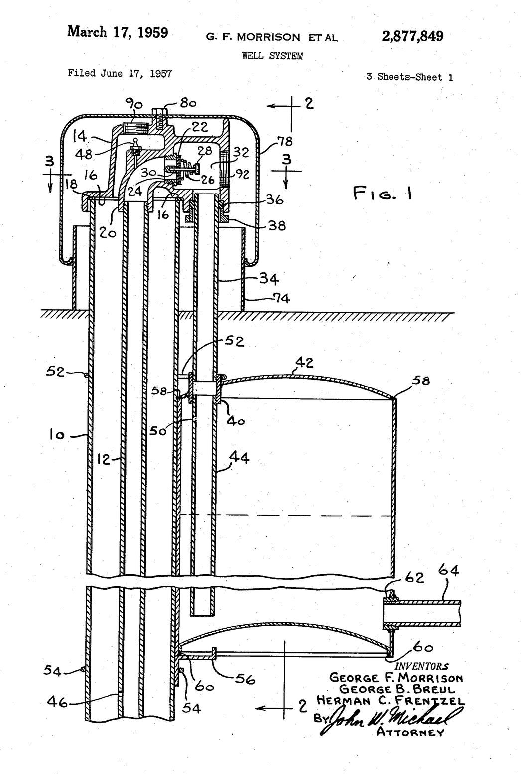
Also Illustrated here are some of the history of G.F. Morrison's well system and his patents. Morrison's principal concerns included designs to prevent freezing of well piping and controls.
On at least some Morrison well systems the water pressure tank was located not indoors as is yours, but in a well pit, therefore below ground level, and next to the top of the well casing.
(Earlier and alternative versions of this system actually placed the water pressure tank right on top of the well casing itself!)
On these systems an air vent system for the pressure tank includes a AVC valve inside of a 1 1/4" diameter x long plastic tube that is placed vertically inside the water pressure tank.
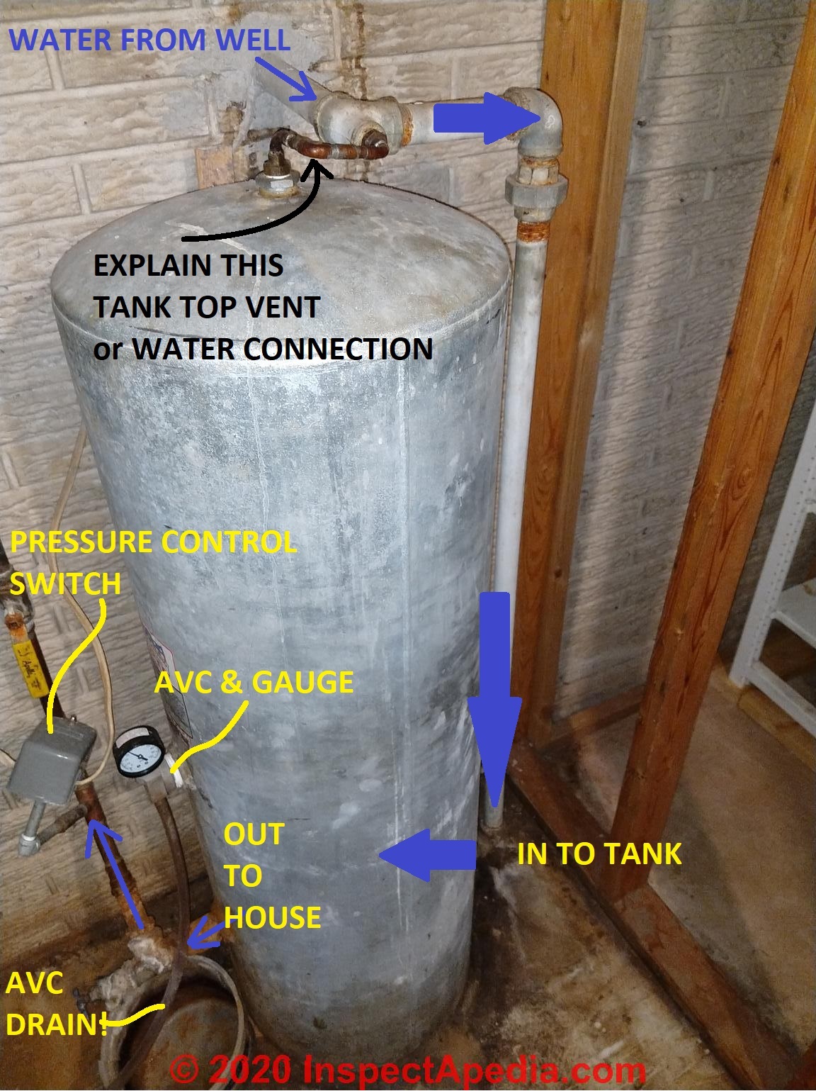
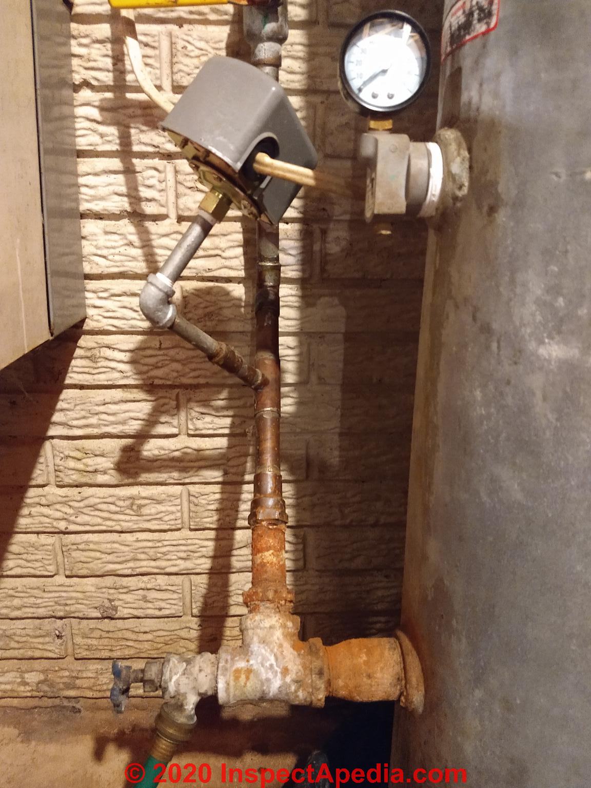
The vent and the pressure control switch were integrated, similar to your water tank side-mounted pressure control shown in your original photo and excerpted just below,
except that your AVC is a conventional one mounted in the side of the tank at about where the tank-full water level would occur,
and your pressure control is on a tee on the house side of the water pressure tank.
From what I've read, you might not normally repair a Morrison well system pressure tank, pressure control, and air volume control by simply installing conventional pressure tank, AVC and control switch devices.
An article "under review" and therefore not readily accessible on wiki how attempts to describe the procedure, from which I excerpt, pending (we hope) an approval and release of the original.
The underlying technical issue is that the Morrison Well system drains water out of the well piping at the pump-off cycle; a water pressure tank that uses an internal bladder and thus that retains some water in the tank, if located as Morrison well system tanks were traditionally, in an area exposed to freezing, the water system and tank and controls may freeze.
Really? Well not necessarily: if **your** water pressure tanks and controls are now indoors in a heated area not subject to freezing you may have an easier and simpler time replacing the tank with a conventional internal bladder tank, snifter valve system, and submersible well pump.
How to Replace the Water Tank on a Traditional Freeze-Resistant Morrison Well System
- Use a top-vented bladderless type water pressure tank - a tank that does not include an internal bladder or diaphragm.
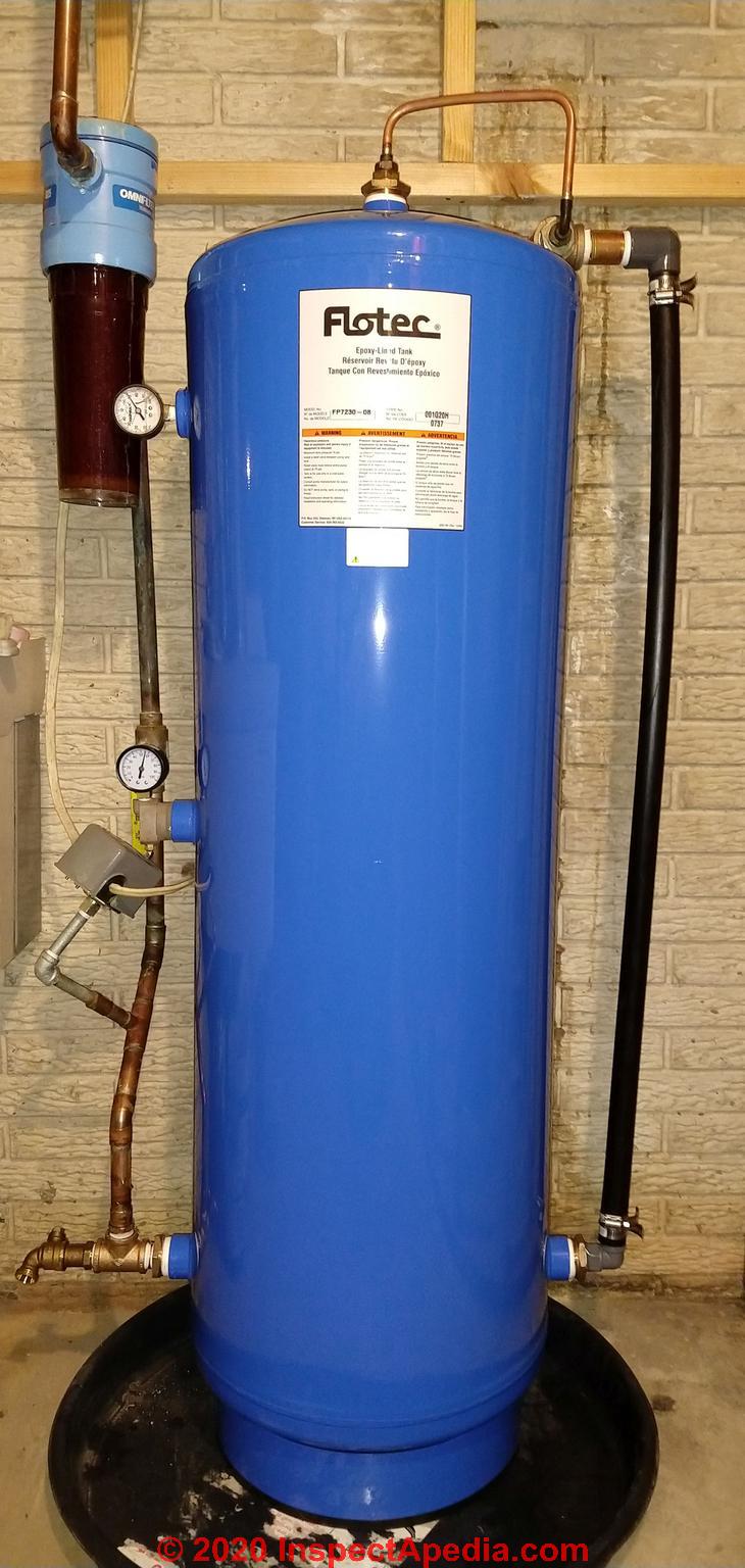
There are several options of these including some of the Flotec and Well-Mate water tanks designed for bladderless or "air over water" systems, including the Flotec FP-7230 that I will illustrate below.
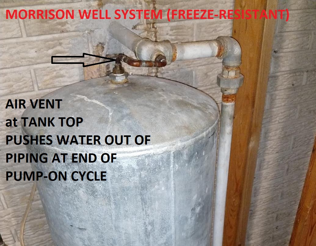
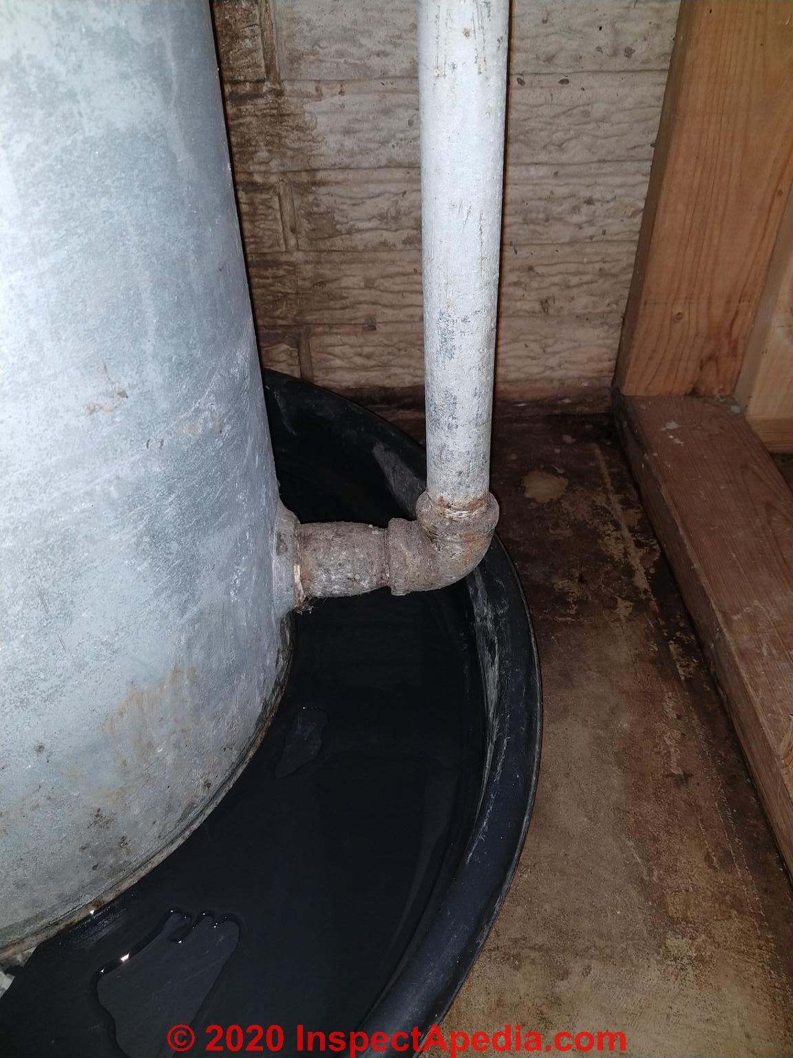
Use a water pressure tank that includes a top tapping to be used to permit air to exit the water tank at its top - just as we see in that small copper pipe in your photo.
- Connect the incoming water line to a tee at the top of the water tank (see photo)
How does this work to vent air?
When the well pump is ON the volume and rate of water passing through the larger piping from the submersible pump in the well and up past the top of the water tank and down to enter the water tank at its bottom are sufficient to hold back most of the air trying to discharge from the top of the pressure tank.
But when the pump is turned OFF(by the pressure control switch) then we have these conditions:
- the water whole system pressure is now at the pump cut-off pressure - higher than when the pump turned-on
- air in the top of the tank can flow "up" and out through the well water pipe where, depending on the total volume (length and diameter) of piping, it can push water out of the pipe and back into the well, through a drain-back valve in the well, leaving the piping empty of water and thus protected from freezing
According to our un-named author in the hard-to-find un-published "how to" article pending at wiki,
... the momentum of the traveling water will help it to continue traveling past this tee whose purpose is to allow air from the top of the tank to pass back to the well.
... Watch out: Do not use a check valve to try to sort the air from the water, it is ... unnecessary.
Technical note: this explanation presumed that the water tank was of the original Morrison design, attached to the actual top of the well casing. That may not be the case for your water tank as I see the tank is indoors and I see that well water piping is entering the building through the foundation wall. But your water system may still be working in the same manner designed by Morrison.
Watch out: typical steel water tank installation instructions like the Flotec instructions I give below, do not describe making use of the tapping at the top of the water tank - because they don't anticipate being used in a Morrison Well System. - Continue the water line to supply water to the tank bottom
(see photos below) where the main in-flow of water to the tank and building supply piping will be delivered. - Additional fittings at the pressure tank bottom: c
onsistent with current well piping & safety standards, include a tank tee and pressure relief valve to protect the water tank from over-pressure; you might also want a tank drain at the tank tee.
Watch out: be sure that the opening pressure of the water tank pressure relief valve is less than the maximum working pressure of the water pressure tank itself. Typically that means the valve will open at around 75 psi - varying by tank model.
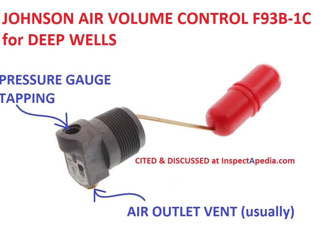
- Install a AVC or Air Volume Control at the tank middle-tapping:
as shown in our annotation on your photo, an AVC, typically also providing a tapping for a water pressure gauge, is installed at a tapping at about the mid-point of the bladderless water tank's height.
This puts the AVC float components at the proper level to maintain the correct air charge in the water pressure tank.
As we explain in our other AVC articles (cited below) a snifter-valve well system
OR
a Morrison Well system each will send a volume of air up the water lines from the well and into the water pressure tank at each pump-on cycle.
The AVC includes a float, activated by rising water in the pressure tank. When the water level in the tank is below mid-point the float drops and the AVC opens to vent excess air from the pressure tank.
When water rises to about mid-level in the water tank, the float rises and the AVC closes; the remaining air is then compressed in the top of the tank to provide water draw-down volume before having to turn the pump back on at the next water usage.
An example, shown below,is the Johnson Controls F93B Air Volume control.
This AVC control is widely sold by local plumbing suppliers and by online vendors like Grainger and SupplyHouse.
We give details about AVCs
at AIR VOLUME CONTROLS, WATER TANK
- Connect the tank bottom outlet to the building water supply piping
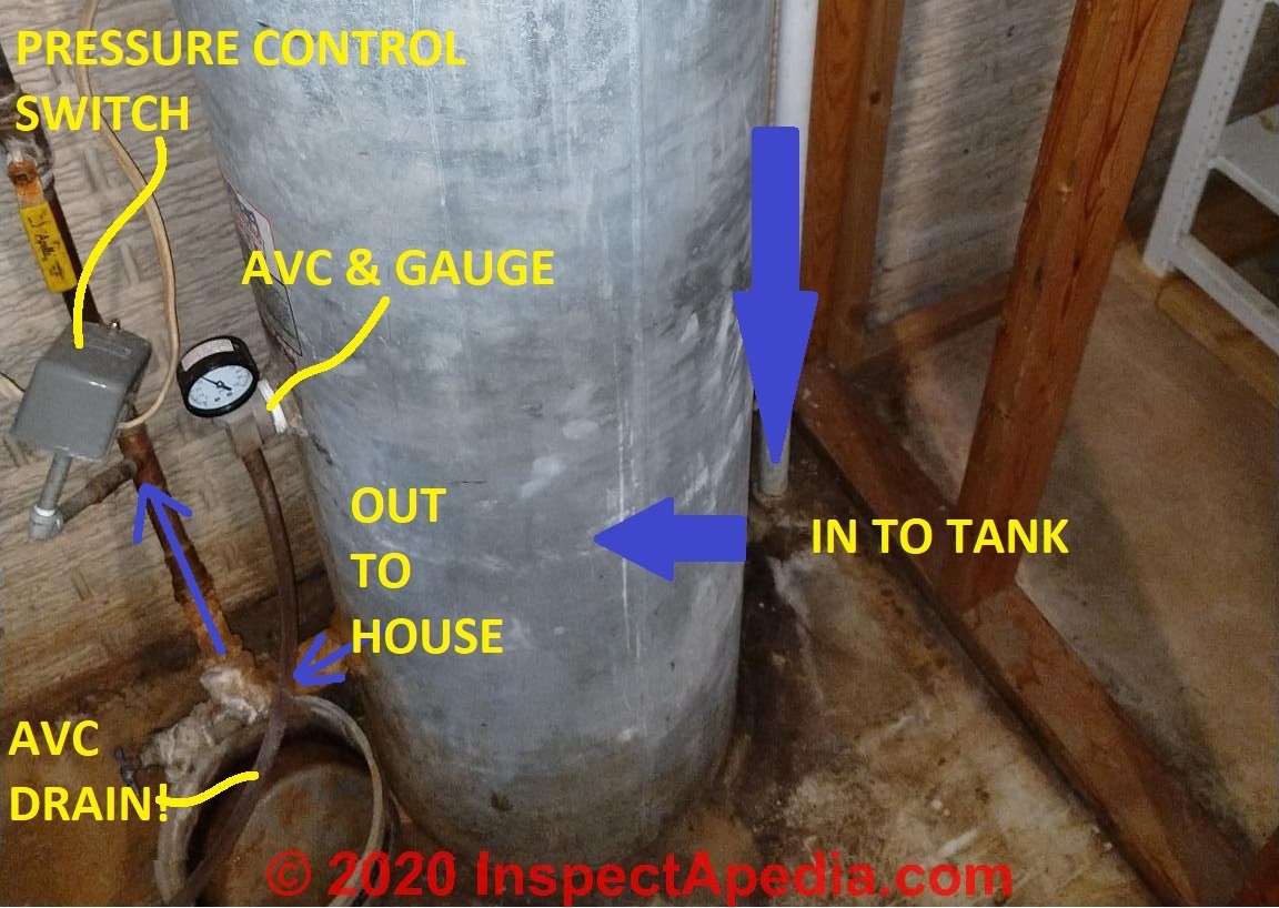
- as shown in your photo above. - Install the water pressure control switch;
in your example the pressure control switch is connected to a tee in copper piping supplying water to the building - at the tank's outlet side. In some installations the pressure control switch might mount on the air volume control if the AVC provides the appropriate 1/4" pipe tapping.
Watch out: some AVCs, at that smaller brass tapping shown in the bottom of the AVC above, include a small air vent. That vent can't be closed, plugged, nor removed, or the AVC will no longer be able to vent air - it wont' work.
Morrison Well System History & Patents & Tank / Control Installation Instructions
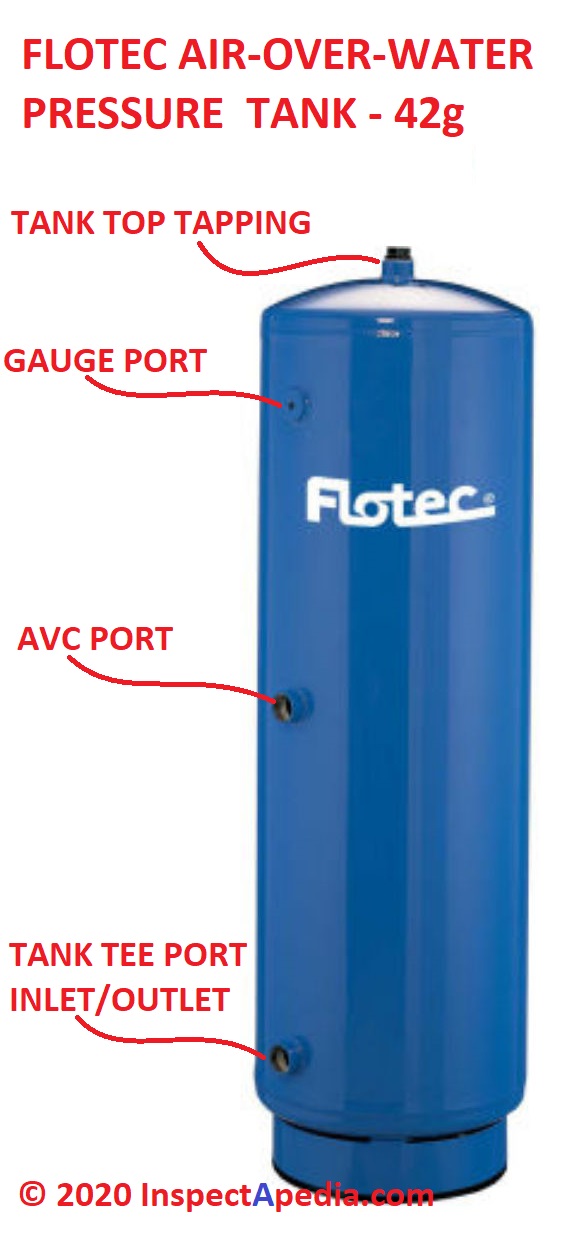
Above: Flotec air over water steel water pressure tank cited & discussed at InspectApedia.com as replacement water tank for Morrison Well Systems.
- AIR DISCHARGE at FAUCETS, FIXTURES - If the AVC stops working - which is common - the symptom will be regular air discharge at plumbing fixtures as the pump cycles on and off.
- Flotec STANDARD EPOXY LINED TANK INSTALLATION INSTRUCTIONS [PDF] (1999) Flotec, PO Box 342, Delavan WI 53115 USA Tel: 1-800-365-6832, Email: flotec@flotecpump.com Website: www.flotecwater.com
- Johnson Controls F93 SERIES AIR VOLUME CONTROL INSTALLATION INSTRUCTIONS [PDF] details of how the AVC works with the snifter valve and drainback valve & how to install the AVC
- Johnson Controls, F93 SERIES AIR VOLUME CONTROLS FOR DEEP WELLS [PDF] Product/Technical Bulletin, (2018) Op. Cit., retrieved 2019/01/30 original source: https://cgproducts.johnsoncontrols.com/MET_PDF/2476643000.pdf
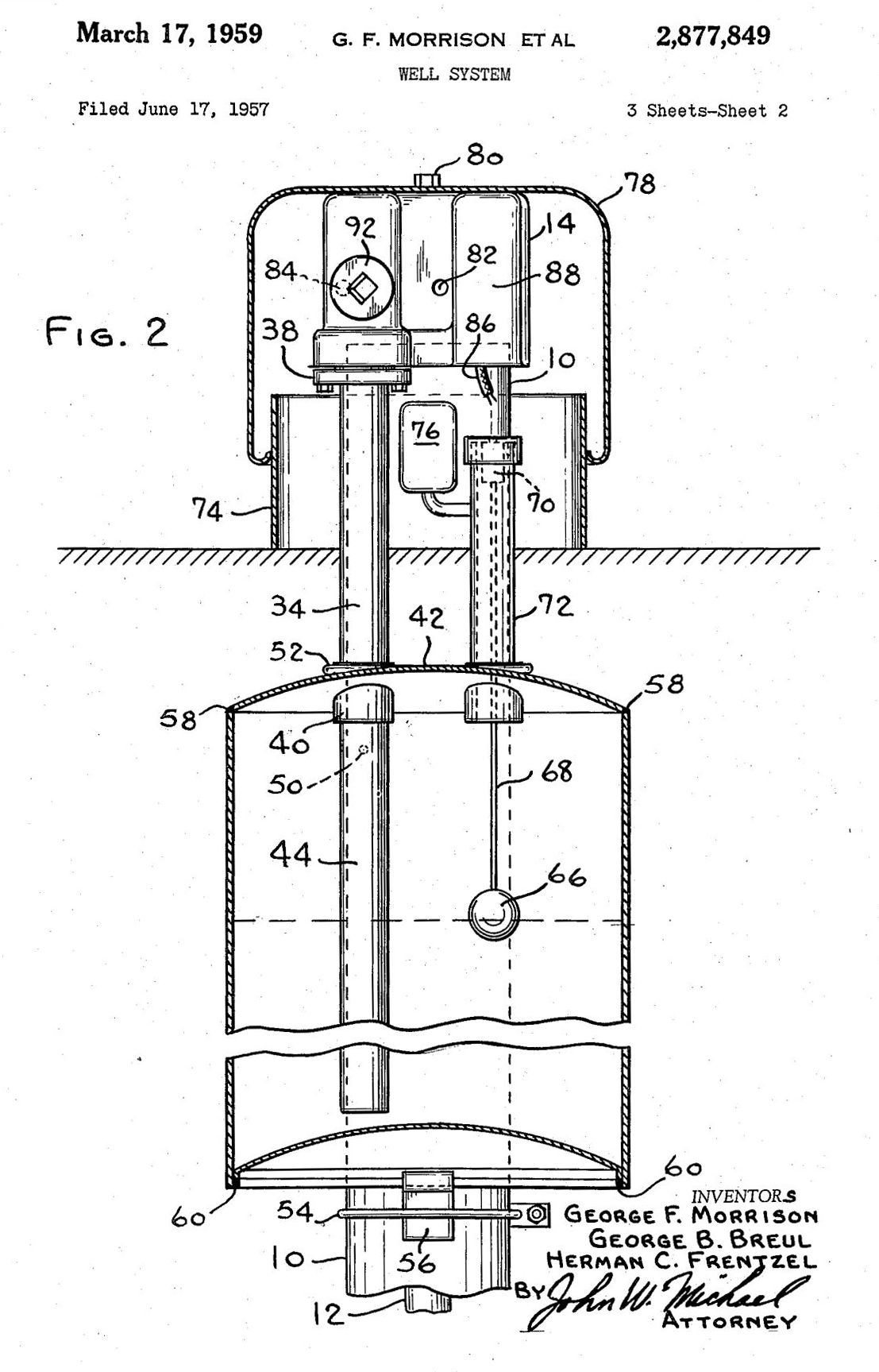
- Morrison, George F., George B. Breul, and Herman C. Frentzel. [Morrison] WELL SYSTEM [PDF] U.S. Patent 2,877,849, issued March 17, 1959. [Shown above]
Excerpts: " The principal object of this invention is to provide an easily installed, readily serviced pitless well system which meets all sanitary code requirements. Another object of this invention is to provide such a system at low cost. Still another object is to provide a well cap adapter which both caps the well and connects to the pressure tank. " - Morrison, George F., and Herman C. Frentzel. [Morrison] WELL SYSTEM [PDF] U.S. Patent 3,095,928, issued July 2, 1963.
Excerpt: The principal object of the present invention is to improve upon the patented well system by providing a check valve arrangement which will not freeze shut and, hence, eliminates the heater and its allied problems.
Another object of this invention is to provide a simple check valve which remains functional over an extremely wide range of temperature. - Morrison, George F., and Herman C. Frentzel. [Morrison Well] CHECK VALVE [PDF] U.S. Patent 3,152,608, issued October 13, 1964.
- Morrison Bros. Co. 570 E. 7th Street P.O. Box 238 Dubuque, IA 52001-0238 USA Tel: 800-553-4840 Email: custserv@morbros.com Website: https://morbros.com/
- PENTAIR WELLMATE UT HP & SP SERIES INSTALLATION INSTRUCTIONS [PDF] top mounted air vent system
...
Reader Comments, Questions & Answers About The Article Above
Below you will find questions and answers previously posted on this page at its page bottom reader comment box.
Reader Q&A - also see RECOMMENDED ARTICLES & FAQs
Where to buy Morrison wellhead check valve?
Where can I get a check valve (insert) for a Morrison wellhead? On 2022-01-16 by Allen Deters -
by Inspectapedia Com Moderator (mod)
@Allen Deters,
If you don't find the proper check valve or valve parts at your local supplier, in the web page above we have some sources for Morrison well systems and morrison well parts including
Morrison Bros. Co. 570 E. 7th Street P.O. Box 238 Dubuque, IA 52001-0238 USA Tel: 800-553-4840 Email: custserv@morbros.com Website: https://morbros.com/
How the pressure tank on a Morrison well system maintains an air charge
Hi, I am having trouble understanding how the pressure tank maintains an air charge if the top vent allows the air charge to push all of the water back into the well through a drainback fitting?
I would think that eventually the pressure in the tank would drop to atmospheric leaving no usable air charge in the pressure tank? Thanks for your reply! On 2020-12-27 by Dana Miller -
Answer by danjoefriedman (mod)
Dana:
Well don't feel bad; I had to read the explanation of how a Morrison well system works with care, more than once, before I got the idea.
Simplifying, the top air vent only allows air to exit the tank during certain stages in the pumping cycle while at other points in the cycle air is injected into the tank.
Details are in the article above at step #2 - which I excerpt below:
When the well pump is ON the volume and rate of water passing through the larger piping from the submersible pump in the well and up past the top of the water tank and down to enter the water tank at its bottom are sufficient to hold back most of the air trying to discharge from the top of the pressure tank.
But when the pump is turned OFF(by the pressure control switch) then we have these conditions:
- the water whole system pressure is now at the pump cut-off pressure - higher than when the pump turned-on
- air in the top of the tank can flow "up" and out through the well water pipe where, depending on the total volume (length and diameter) of piping, it can push water out of the pipe and back into the well, through a drain-back valve in the well, leaving the piping empty of water and thus protected from
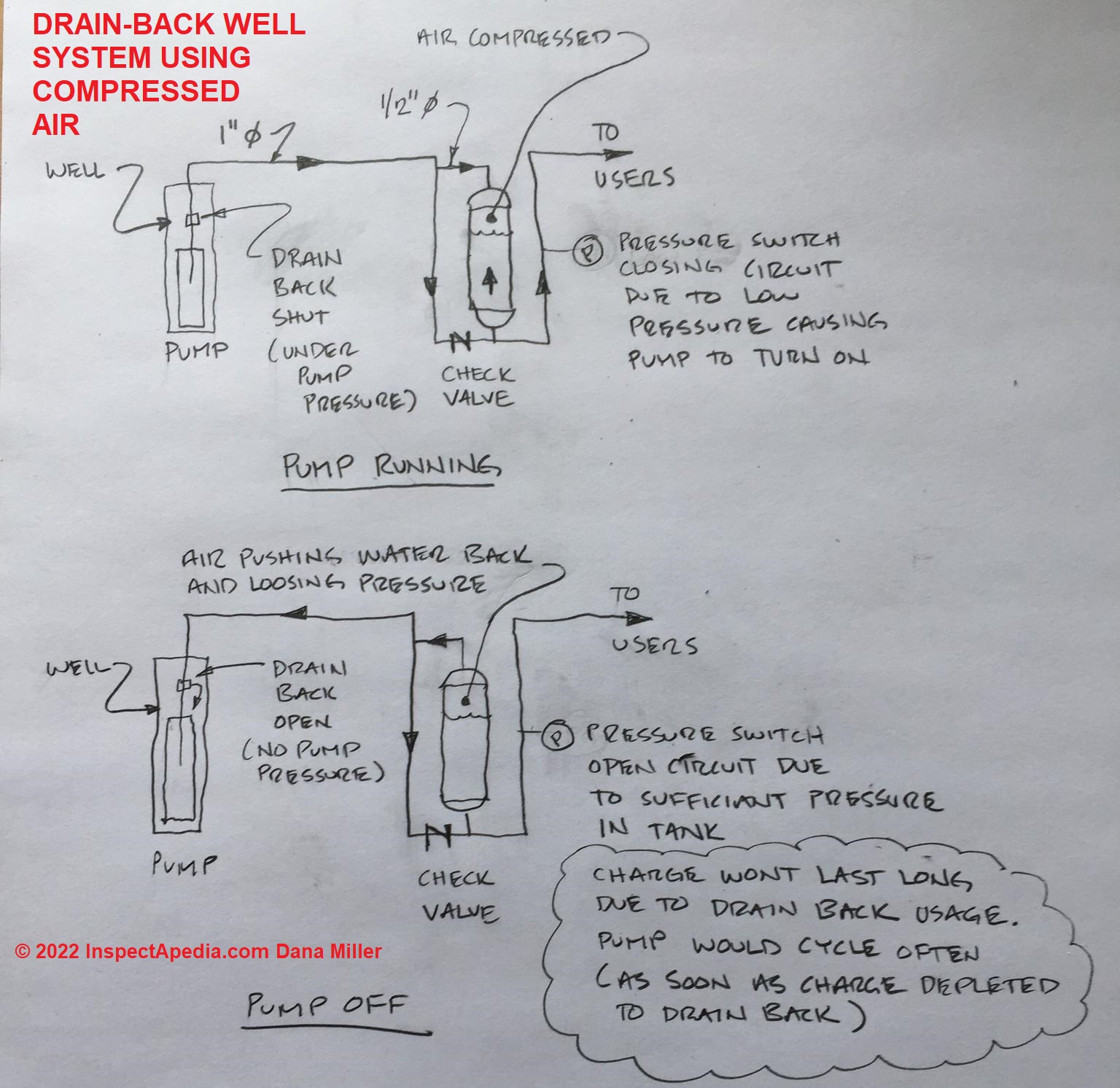
I may not have this correct, but the way I think of the Morrison well system working is that at the end of the pump-on cycle, a significant volume of air in the pressure tank is at the pump cut-off pressure, say 60 psi; the combination of volume and pressure pushes water in the well supply pipe away from the pressure tank and down to some depth, but it is never open to the atmosphere.
So at a stable point there is air both in the well piping and remaining in the top of the pressure tank as well.
For example, just 1 ATM or about 14.6 psi is enough to push air out of a vertical well water pipe down to a depth of 30 feet.
Think of the air-filled well pipe as simply an extension of the volume of air in the top of the pressure tank, joining in pushing water out of the tank when a building occupant opens a tap.Take a look at some of the installation and operation manuals that I provide above as downloadable PDF files as those may also be helpful, e.g. the Flotec tank installation manual.
Keep me posted, and post some photos (1 per comment) when you can as that may help others or may permit a useful comment.by Dana Miller
Thanks for the reply Danjoe. I am building an offgrid home in the Rocky Mountains and am struggling with my water line bury depth from my well discharge (freeze protection). I would love to "pressure back", instead of "gravity drain back".
I do understand the concept that you have described but there is still an aspect that I cant figure out.
How does the water tank hold a pressure charge long enough to be usefull to the downstream tank users if the charge exits the tank to help with the drainback and there is no way to stop the charge from reducing to pump kick on pressure rather quickly.
To me this would cycle the pump back on in a very short period of time as the pressure in the tank rapidly droped? How is useful pressure maintained in the tank?
I have attached a quick sketch that may be helpful? I am sure I am missing something simple?
[Sketch shown above]
How to Identify and Repair a Morrison Well System
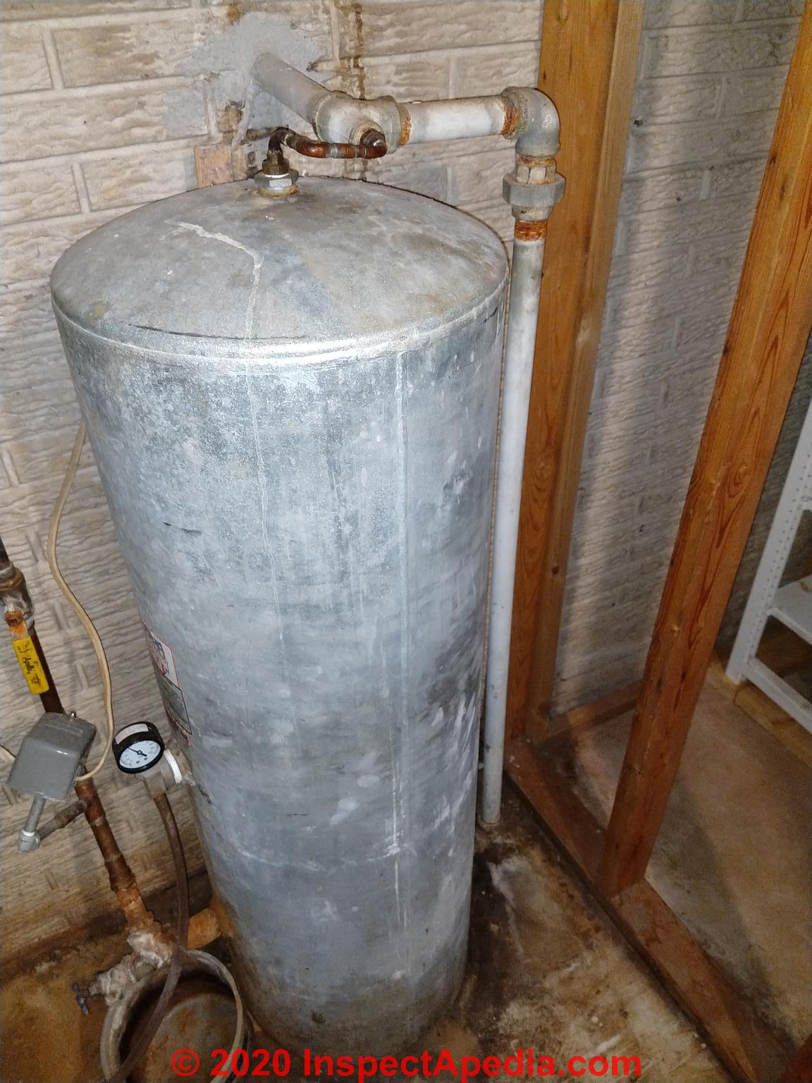
I have a drain back system and there is an AVC on the side of the tank, no check valve as far as I can tell. I believe the snifter valve is in the well cap as there is nothing on the inside plumbing.
I suspect the tube aides in draining the feed line.
I need to replace the tank and need to know how to replace or replicate the functionality. 2020-10-18 by Evan -
Solution by (mod) -
Evan
are you referring to the copper piping connected to galvanized piping at the tank top?
can you show me another photo with more of the piping into and out of this pressure tank?
Is that galvanized piping coming through the wall above the tank the water line coming in from your well?Evan
"are you referring to the copper piping connected to galvanized piping at the tank top?" YES
"Is that galvanized piping coming through the wall above the tank the water line coming in from your well?" YES
Water in picture:
Water out picture.
by (mod) -
OK so it looks to me as if a galvanized line comes in above the tank and runs down to send water into the tank bottom
and
water out to the house, in your last photo, also exits at the tank bottom.
I don't know why there's a little additional connection at the tank top; but that won't prevent me from making a guess: I think it's part of an air vent system.
When the pump is running and so sending water in that galvanized well line, most of the water is entering at the tank bottom, but
it's possible that air in the well line at the start of a pump-on cycle finds its way more-easily into the top of the water tank (where the tank's air charge would normally reside) than in through that fitting at the tank bottom; that can be a type of water tank top-venting system.
When water is coming up that same well line it's pushing into both the tank top and (mostly) the tank bottom.
Someone may have figured that they were getting improved control over the air charge in the pressure tank with that arrangement;
In any event excess air ought to be venting out the bottom of that AVC control - (below the pressure gauge in your last photo) - but those are famous for getting clogged and jammed; The white teflon tape on your AVC hints that maybe it's been replaced recently.by Evan
Your guess sounds reasonable but what would stop the air from leaving the tank though that line?
Is there a chance that the water line wouldn't drain or I'd wreck something in the well if I didn't recreate that setup?
by (mod) -
Watch out: yes you almost certainly need to replace the piping on the new water tank to match the original unless other installation controls and features of this freeze-protection system are also changed out.
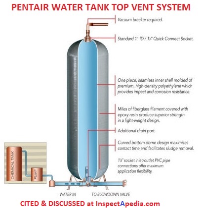
What am I thinking? Perhaps that in concept there are **other** top-vented water pressure tanks that include in-tank float controls such as by Pentair as I'll illustrate below.
However your tank's water piping don't match those. It depends solely on incoming water pressure and flow rate past the top of the pressure tank.
So if I was not clear: I don't know how this system works but we're researching it.[Note: the explanation is given above, describing how a Morrison Well System is designed to prevent water pipe freezing by using air to empty piping or other water components exposed to freezing]
Watch out: do not remove that unexplained copper piping and tee.
Once back in the dark ages of my plumbing career I inspected an old indirect fired water heater - a tank - heated by a side-arm coil on an antique down-fired GE boiler - itself a collector's item from the 1940s.
There was one piping loop that made absolutely no sense to me whatsoever and seemed totally redundant.
So yep, I took it off. And the homeowner had no more hot water. It was a loop that circulated hot water by convection in a way I'd not understood.
So
1. don't take this connection off of your water tank
2. let's see if we can find a plumber older than I am - which will be difficult - who knows why someone did this to your water tank - which may be interesting.
I'm also doing some further research [reported later in this discussion]. Illustrated above: a sketch from one of Morrison's early well system patents.There have been some patents that used a tank-top fitting on a bladderless water pressure tank such as
- Schroeder, David H. "Bladderless pre charged pressurized liquid delivery system." U.S. Patent 5,868,280, issued February 9, 1999.
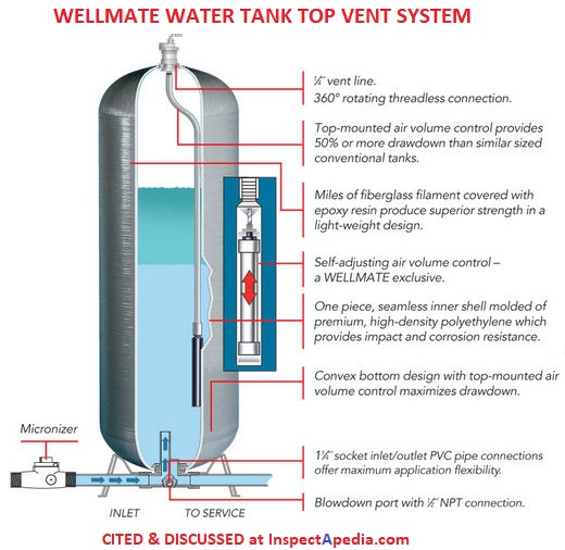
A claim from Wellmate is that in some designs a top-mounted air vent can provide a greater drawdown volume as shown in this sketch
See details at this
- PENTAIR WELLMATE UT HP & SP SERIES INSTALLATION INSTRUCTIONS [PDF] that describe a top mounted air vent system
And some bladderless pressure tanks use a top fitting similar to yours but require a vacuum breaker (Pentair)
[Click to enlarge any image]
Also see WATER TANK CAPTIVE AIR vs TRADITIONAL WellMateContinuing to look around:
by Evan
It's a Morrison Well System if that makes a difference.
Recommendations by (mod)
That explains that top piping.
Our discussion is now detailed starting
at MORRISON WELL SYSTEM FUNCTION & REPAIR
Wow! Thanks for putting this all together for me
Wow! Thanks for putting this all toghether for me. I certainly didn't expect to get my own page out of this :) On 2020-10-21 by Evan -
I'm a bit surprised that it's able to push the water back out of the service line, 12' back and 5' rise, into the well. But it works great. The line is only three feet deep but it's never frozen through a Wisconsin winter.
Attached is a picture of the finished job.
by (mod) - volume of water in well pipes easily displaced by air at sufficient pressure
Thank you for the update and photo, Evan. Yes it's indeed your page, MORRISON WELL SYSTEM FUNCTION & REPAIR inspectapedia.com/water/Morrison-Well-System-Repair.php
and I'm grateful to you for bringing this type of water system to our attention. It was new to me and interesting.
What makes the Morrison system work, I think, are at least two ideas:
1. the volume and rate and pressure of incoming water from the well during pump-on cycle prevent simple loss of all of the air charge out of the pressure tank; if all that air charge were lost we'd have no draw-down volume benefit from the pressure tank and the well pump would short-cycle during water use.
2. the volume of air has to be sufficient to push water out of the piping that's at risk of freezing. We've done this calculation - of the volume inside of water pipes and well casings - and discuss it at
WELL FLOW RATE inspectapedia.com/water/Well_Flow_Rate.php
and at
VOLUME of WATER IN a PIPE - CALCULATION
and
...
Continue reading at DRAIN BACK & SNIFTER VALVE INSTALLATION / REPLACEMENT or select a topic from the closely-related articles below, or see the complete ARTICLE INDEX.
Or see these
Recommended Articles
- AIR DISCHARGE at FAUCETS, FIXTURES
- AIR VOLUME CONTROLS, WATER TANK
- SNIFTER & DRAIN BACK VALVES
- DRAIN BACK / BLEED BACK VALVE / SNIFTER VALVE PURPOSES
- DRAIN BACK & SNIFTER VALVE SYSTEM COMPONENTS
- DRAIN BACK & SNIFTER VALVE OPERATION
- DRAIN BACK / SNIFTER VALVE TROUBLESHOOTING
- DRAIN BACK & SNIFTER VALVE INSTALLATION / REPLACEMENT
- DRAIN BACK / SNIFTER VALVE CONVERSION to BLADDER-TYPE WATER TANK
- DRAIN BACK / BLEED VALVE / SNIFTER VALVE SUPPLIERS
- WATER PUMP & TANK I&O & REPAIR MANUALS - installation, operation & repair guides for all brands
- WATER PUMP SHORT CYCLING CAUSES
- WATER TANK DIAGNOSIS & REPAIR - home
- WATER TANK CAPTIVE AIR vs TRADITIONAL WellMate
- WATER TANK: USES, TROUBLESHOOTING - home
- WATER TANKS, STEEL
Suggested citation for this web page
MORRISON WELL SYSTEM FUNCTION & REPAIR at InspectApedia.com - online encyclopedia of building & environmental inspection, testing, diagnosis, repair, & problem prevention advice.
Or see this
INDEX to RELATED ARTICLES: ARTICLE INDEX to WATER SUPPLY, PUMPS TANKS WELLS & SPRINGS
Or use the SEARCH BOX found below to Ask a Question or Search InspectApedia
Ask a Question or Search InspectApedia
Share this article:Try the search box just below, or if you prefer, post a question or comment in the Comments box below and we will respond promptly.
Search the InspectApedia website
Note: appearance of your Comment below may be delayed: if your comment contains an image, photograph, web link, or text that looks to the software as if it might be a web link, your posting will appear after it has been approved by a moderator. Apologies for the delay.
Only one image can be added per comment but you can post as many comments, and therefore images, as you like.
You will not receive a notification when a response to your question has been posted.
Please bookmark this page to make it easy for you to check back for our response.
IF above you see "Comment Form is loading comments..." then COMMENT BOX - countable.ca / bawkbox.com IS NOT WORKING.
In any case you are welcome to send an email directly to us at InspectApedia.com at editor@inspectApedia.com
We'll reply to you directly. Please help us help you by noting, in your email, the URL of the InspectApedia page where you wanted to comment.
Citations & Reviewers
In addition to any citations in the article above, a full list is available on request.
- [1] U.S. Gauge Special Application Gauges: Type 300L and 310WJ Air Volume Controls, product description, 2002, Ametek® Inc, U.S. Gauge, 820 Pennsylvania Blvd., Feasterville PA 19053, USA, Tel: 215-355-6900 www.ametekusg.com Customer Service: 863-534-1504, web search 03/23/2011, original source: http://www.jlwinstruments.com/PDF_files/D17_MODEL300-310.PDF Sadly this URL now reroutes to a dead end
- [2] AMTEK, 900 Clymer Avenue 8600 Somerset Drive Sellersville, PA 18960 U.S.A. or Customer Service at AMTEK, Largo, FL 33773 U.S.A.Sales/Technical Support: 215-257-6531, Customer Service: 727-536-7831, Website: www.amtekusg.com, Email US Gauge at usg.sales@ametek.com.
- [3] flosource.com/ provides links to some US Gauge air volume control products installation and adjustment
- In addition to citations & references found in this article, see the research citations given at the end of the related articles found at our suggested
CONTINUE READING or RECOMMENDED ARTICLES.
- Carson, Dunlop & Associates Ltd., 120 Carlton Street Suite 407, Toronto ON M5A 4K2. Tel: (416) 964-9415 1-800-268-7070 Email: info@carsondunlop.com. Alan Carson is a past president of ASHI, the American Society of Home Inspectors.
Thanks to Alan Carson and Bob Dunlop, for permission for InspectAPedia to use text excerpts from The HOME REFERENCE BOOK - the Encyclopedia of Homes and to use illustrations from The ILLUSTRATED HOME .
Carson Dunlop Associates provides extensive home inspection education and report writing material. In gratitude we provide links to tsome Carson Dunlop Associates products and services.
 |
HOME | ABOUT | ASK a QUESTION | CONTACT | CONTENT USE POLICY | DESCRIPTION | POLICIES | PRIVACY | |
| © 2026 - 1985 Publisher InspectApedia.com - Daniel Friedman | |||||||||