 Electrical System Inspect, Install, Repair
Home Page & Index to Articles
- POST a QUESTION or COMMENT about building electrical systems, panels, breakers, wiring installation, inspection, diagnosis, & repair
This page provides an index to building electrical system installation, troubleshooting & repairs & electrical hazard at residential & light commercial building electrical systems.
Examples of information we provide in these articles include how to install, inspect, & troubleshoot building electrical systems, appliances, components.
Here we also provide articles on how to detect & report electrical hazards, defects in residential and commercial electrical panels, switches, fixtures, electrical wiring & grounding systems. Proper electrical repair methods for unsafe electrical conditions.
We also discuss safety for the electrical inspector, aluminum electrical wiring hazards, how to determine service voltage and ampacity, how to inspect electrical panels, and significant electrical hazards of Federal Pacific Electric Stab-Lok breakers and panels, Federal Pioneer product warnings, certain Square-D product concerns, Zinsco and Sylvania circuit breakers and panels, multi-wire branch circuit protection, inspection and repair of low voltage wiring systems, and proper installation of lightning protection systems on buildings.
InspectAPedia tolerates no conflicts of interest. We have no relationship with advertisers, products, or services discussed at this website.
- Daniel Friedman, Publisher/Editor/Author - See WHO ARE WE?
Electrical Hazards in Buildings, Electrical Inspection Procedures, Electrical Repair Procedures
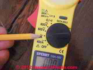
This topic home page provides an index to key building electrical system topics addressing electrical system or component installation, inspection, troubleshooting & repair.
We also discuss electrical and electrical inspector safety, testing, standards, and controls.
To find what you need quickly, if you don't want to scroll through this index, you are welcome to use the page top or bottom SEARCH BOX to search InspectApedia for specific articles and information.
[Click to enlarge any image]
- SAFETY HAZARDS & SAFE ELECTRICAL INSPECTION PROCEDURES - for Electrical and Home Inspectors at Residential Electric Panels
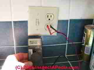
- AFCI GFCI WIRING, TESTING & SAFETY - GFCI Ground Fault Circuit Interrupter Receptacle Defects & Testing procedures
- ALUMINUM WIRING - Information Website for Aluminum Electrical Wiring Hazards and Repairs: in-depth authoritative info, photos, documents including selection of proper vs. ineffective repair methods. E.g.: Ideal 65 "Twister" purple connector fails in field and lab testing with aluminum wire
- AMPACITY & VOLTAGE - of an Electrical Service: How to determine the electrical service size or ampacity and service voltage (120/240) entering a Building
- AMPS MEASUREMENT METHODS - how to use an ammeter to perform simple current tests
- ARC FAULT CIRCUIT INTERRUPTERS - what are they, how do AFCIs work, where are they required to be installed? Also includes notes on GFCIs and the 2008 NEC electrical code
- BACKUP ELECTRICAL GENERATORS - for emergency power
- CADET HEATERS RECALL - CPSC notice supplemented with identification and heater failure photos
- CAPACITOR TYPES, for MOTORS - electric motor start & run capacitors
- CHALLENGER ELECTRIC PANELS - bus overheat field reports in Challenger® electrical panels, relation to FPE Stab-Lok®?
- CIRCUIT BREAKER FAILURES - fails to trip failure at aluminum bus-to-circuit breaker connection - field report and photographs
- CIRCUITS, ELECTRICAL - electric circuit basics for homeowners, electrical shorts, definitions of AC/DC, watts, amps, volts, etc.
- CODE BASICS, ELECTRICAL - electrical code information for homeowners. Can I do my own wiring?
- CONDUIT, ELECTRICAL - information for homeowners & home inspectors.
- COPELAND ELECTRICAL HANDBOOK [PDF] - from Emerson Climate Controls
- CORROSION & MOISTURE SOURCES in PANELS, Roger Hankey 2010, and CORROSION in ELECTRICAL PANELS, Daniel Friedman, 1992, 2009 - discuss the sources of water or moisture intrusion in electrical panels and causes of rust or other safety concerns
- Electrical System Inspection Classes -
- ALUMINUM WIRING CLASS for ELECTRICIANS - [PDF] Class by Daniel Friedman - originally a Power Point Presentations for Milestone Elec. Dallas TX
- FPE STAB-LOK Class for ELECTRICIANS - [PDF] Class by Daniel Friedman - originally a Power Point Presentations for Milestone Elec. Dallas TX
- ZINSCO ELECTRIC PANEL CLASS - [PDF] Class by Daniel Friedman - originally a Power Point Presentations for Milestone Elec. Dallas TX
- ELECTRICAL SAFETY COURSE for ELECTRICIANS - [PDF] Class by Daniel Friedman - originally a Power Point Presentations for Milestone Elec. Dallas TX
- ELECTRICAL SAFETY & ACCIDENTS CLASS for HOME INSPECTORS - [Web page] Daniel Friedman - paper presented to the Connecticut Association of Home Inspectors, CAHI 26 March 2008
- ELECTRICAL PANEL INSPECTION CLASS - [Web page] Daniel Friedman - safety for electrical inspectors, electrical panel, fusing, wiring defects, defective products
- "Inspecting Residential Electrical Panels," Daniel Friedman, HVASHI, September 12, 2002 Annual Seminar
- "Inspection of Electrical Systems & Special Concerns," Daniel Friedman, ASHI/CAHI/OAHI/IAEI Conference, Toronto, Ontario, 10/19-21/1995
- DEFINITIONS of ELECTRICAL TERMS - Amps, Volts, Watts, Resistance and other electrical terms are defined and illustrated with sketches
- "Determining Service Ampacity," Daniel Friedman, Alan Carson, The ASHI Technical Journal, Vol. 2 No. 1, Winter 1992
- DIRECTORY OF ELECTRICIANS - if you need to hire an electrician with special skills or familiarity with aluminum electrical wiring, FPE Stab-Lok replacement panels, Zinsco replacement panels, etc., here is a directory of professionals
- DMM DIGITAL MULTIMETER USE - how to use test instruments to perform basic electrical wiring or equipment diagnostic tests
- EFFICIENCY of 120V vs 240V EQUIPMENT
- EFFICIENCY of 120V vs 240V EQUIPMENT FAQs
- ELECTRIC METERS & METER BASES - inspection and problem diagnosis
- ELECTRIC MOTOR DIAGNOSTIC GUIDE - describes steps & tests for both offline and online electric motor circuit analysis (MCA) test procedures for hard starting or non-starting A/C electric motors
- ELECTRIC POWER LOSS / FLICKERING LIGHTS - what causes flickering lights, voltage fluctuations, and similar electrical problems & how do we find and fix the trouble?
- ELECTRICAL DISTRIBUTION PANELS - in buildings, safety for electrical inspectors, electrical panel, fusing, wiring defects, defective products. Inspection Class Presentation
- ELECTRICAL SERVICE ENTRY WIRING - how is electrical power brought to the building: inspection, troubleshooting, defects
- ELECTRICAL SYSTEM REPAIR FAQs - diagnostic questions & answers about inspecting or repairing electrical systems in building: wiring, fixtures, receptacles, electrical panels, lights, light fixtures, GFCIs, AFCIs, etc.
- ELECTRICAL WIRING for STRUCTURAL INSULATED PANEL (SIP) BUILDINGS
- ELECTRICIANS DIRECTORY - how to find an electrician who knows proper repairs for aluminum wiring, FPE panels, Zinsco panels etc.
- EMF RF FIELD & FREQUENCY DEFINITIONS - defines and explains electromagnetic field (EMF) or electro-magnetic radiation (EMR) and related terms such as radio frequency - RF, hertz or cycles, megahertz, medium frequency MF, very high frequency VHF, ultra high frequency UHF, megahertz MHz, gigahertz GHz, terahertz THz
- FEDERAL PACIFIC ELECTRIC (FPE) PANEL - Stab-Lok Circuit Breaker Panel Hazards Latent fire hazards, in-depth authoritative research, documents, advice on Stab-Lok electric panel and circuit breaker failures and what to do when this equipment is found in buildings.
- FEDERAL PIONEER NCO15 / NC015CP CIRCUIT BREAKER RECALL- from Schneider Electric in Canada
- FPE STAB-LOK PANEL IDENTIFICATIONS - is yours one of these? ALSO: A History of the FPE Stab-Lok Issue
- FPE FIRES: FAILURE REPORTS - FPE breaker fails, results in fires: field reports
- FEDERAL PACIFIC ELECTRIC PANEL FIRES WAITING TO HAPPEN - Debate Waiting to Be Ended, detailed article
- FEDERAL PACIFIC ELECTRIC PANEL REPLACEMENTS - two cost and method options for FPE panel replacement
- FPE STAB-LOK PANEL TECHNICAL REPORT - St. Louis ASHI Seminar including: Hazard Summary & Independent Tests confirms Stab-Lok failures
- FLUORESCENT LIGHT REPAIRS
- FUSE REPLACEMENT - fuse types, choices, replacement procedures
- FUSE TEST - how to check out the main fuse or circuit breaker
- GENERATORS, ELECTRICAL - how residential electrical generators are selected, installed, inspected for safety
- GFCI WIRING, TESTING & SAFETY - GFCI Ground Fault Circuit Interrupter & AFCI Arc-Fault Detector Defects & Testing procedures
- "Ground Fault Circuit Interrupters, How Do They Work?" Daniel Friedman [as Journal Staff], The ASHI Technical Journal, Vol. 2 No. 1, Winter 1992
- GROUND SYSTEM INSPECTION, ELECTRICAL - how to inspect, troubleshoot, and repair ground system wiring in buildings
- HERTZ DEFINITIONS KHz MHz GHz THz - definitions
- KNOB & TUBE ELECTRICAL WIRING - identification, inspection, evaluation, and safety guide advice for home owners & inspectors
- KNOB & TUBE WIRING & Home Owners' Insurance [Carson Dunlop Associates, Toronto]
- LIGHT SWITCH WIRING DETAILS
- LIGHTING, EXTERIOR GUIDE - home
- LIGHTING, INTERIOR GUIDE - home
- LIGHTING OVER STAIRS & AT EXITS
- LIGHTNING PROTECTION SYSTEMS - Lightning Protection Systems & Services, lightning rods, grounding - lightning strike data
- LIGHTNING PROTECTION SYSTEMS Daniel Friedman [as Thomas Misciewicz], The ASHI Technical Journal, Vol. 2 No. 1, Winter 1992
- LOW VOLTAGE ELECTRICAL WIRING
- LOW VOLTAGE WIRING REPAIR & REPLACEMENT - GE®, Remcon, Sweepe, Bryant, Sierra, other brands, and newer Touch-Plate® low voltage wiring systems. Low voltage lighting switches, relays, transformers, transconverters
- MULTI-WIRE BRANCH CIRCUIT INSPECTION - and defects
- OLD HOUSE ELECTRICAL SYSTEMS - special hazards associated with old electrical wiring & old electrical systems in buildings
- OUTLET, HOW TO INSTALL - guide for home owners & home inspectors - it's easy but important details make the difference between a safe installation of an electrical receptacle and one that is both dangerous and illegal
- PUSHMATIC - BULLDOG PANELS
- RUST & CORROSION in Electrical Panels - A Study and Report on Frequency and Cause for Electrical and Home Inspectors at Residential Electric Panels
- SAFETY for ELECTRICAL INSPECTORS - Safety Considerations for the Electrical Inspector," Daniel Friedman, The ASHI Technical Journal, Vol. 2 No. 1, Winter 1992
- SAFETY HAZARDS & ACCIDENT PREVENTION - paper presented to the Connecticut Association of Home Inspectors, 26 March 2008
- SQUARE-D ELECTRICAL PANEL RECALL - Counterfeit Square D Recall
- SQUARE-D GFCI RECALL
- SQUARE-D & FEDERAL PIONEER AFCI WARNING - (also Federal Pioneer - Schneider Canada)
- SQUARE D CIRCUIT BREAKER RECALLS, CPSC - include a Square D GFCI circuit breaker distributed by Square D, and a Counterfeit Square-D circuit breaker sold through Scott Electric
- TURN OFF ELECTRICITY in a WET or FLOODED BUILDING - how to
- TURN ON ELECTRICITY - RESTORE UTILITIES AFTER FLOODING - how to
- VOLTS / AMPS MEASUREMENT EQUIP - equipment types & choices for measuring or detecting voltage & amperage
- VOLTS MEASUREMENT METHODS - how to actually measure electrical voltage in a building or at electrical equipment or devices
- WIND TURBINES & LIGHTNING - lightning protection and extra protection from lightning damage for wind turbine electrical generator systems and their controls and batteries
- ZINSCO ELECTRICAL PANEL & CIRCUIT BREAKER FAILURES - overheating, explosions, failure to trip, burn-ups involving Zinsco & certain Sylvania electrical panel components
- ZINSCO PANEL REPLACEMENTS - of repair (replacement) options for Zinsco Electrical Panels and Zinsco-type Sylvania Electric Panels
...
Reader Comments, Questions & Answers About The Article Above
Below you will find questions and answers previously posted on this page at its page bottom reader comment box.
Reader Q&A - also see RECOMMENDED ARTICLES & FAQs
On 2023-10-11 by Dan - I did my own knob and tube re-wiring: did I make mistakes?
My house was originally wired with the old rubber-insulated wire and knobs and tubes.
Sometime before we moved in (1997) the old wire was replaced with #12 THHN that was run along the old circuit paths through the tubes and fixed in place with the old knobs.
The original splices were soldered 'Western Union' splices made outside boxes.
I have remade most of these splices with wire nuts inside metal junction boxes and added lots of tape to the others. It seems to me that it would be safe to blow in cellulose insulation.
Am I wrong? I have marked all the boxes with upright sticks.
On 2023-10-11 by InspectApedia DF (mod) - knob and tube wiring replacement/update
@Dan,
Going from #14 old knob and tube wire to new #12 wire is a nice safety improvement in that the larger wire size, provided you're still using it on 15A circuits, will run cooler.
But I'm not clear on exactly what wire you're running: did you really run single strand #12 THHN wire along knob and tube connectors?
Normally modern house wiring is run - as doubtless you know - in a combination of hot+neutral+ground conductors that not only have each its own insulator, but there is additional insulation provided by an external jacket that wraps all 3 wires.
Individual strand THHN wire like this Southwire 22968201 Stranded THHN 12 Gauge Building Wire, 500-Feet, Green (shown below) is NOT intended to run free through a building, not in air, and not in insulation.
Rather it expects to be run through conduit:
Here is Southwire's product description:
This THHN 12 gauge building wire is primarily used in conduit and cable trays for services, feeders and branch circuits in commercial or industrial applications. It is designed for use in dry locations at temperatures not to exceed 90 degree Celsius or wet locations at 75 degree Celsius. It is stranded uncoated copper wire insulated with flame retardant PVC compound. Can be used for residential and industrial lighting and power. Meets or exceeds all applicable ASTM specifications. Features conduits and raceways installed underground.
So I'm left both admiring your creativity but very nervous about your electrical wiring and I'm doubtful that your local electrical inspector is going to approve it.
In GENERAL, knob and tube wiring is legal and can continue in use in most jurisdictions as long as it's not damaged AND PROVIDED that it is not modified or extended.
You've done a remarkable modification - using ceramic knobs and tubes to route modern THHN #12 wire that was not designed for that application - with, or without being buried by insulation.
In my OPINION you should STOP WORK immediately on this design and get your local electrical inspector out to the job to see what she or he has to say - lest you spend more time and money that have to be undone.
Thank you so much for an important and helpful "knob and tube wiring replacement/update" question.
On 2023-08-06 by Anonymous - do I have to pay to replace my Federal Pacific Electric Panel?
Will the company that produced the FPE breaker box replace them at no cost?
On 2023-08-06 by InspectApedia Publisher - Will the company that produced the FPE breaker box replace them at no cost?
@Anonymous,
No, although there was at one point money budgeted for a recall with one small exception there has been none and you're on your own.
On 2023-06-01 by Stan C - can I use multiple small gauge wires to build up to a higher-amp circuit?
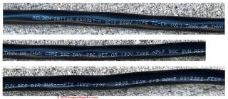 Hi! I have a brand new cable qualified for NPLF (non power limited fire systems). Text on the cable says (see photo):
"BELDEN (brand name) 600V Type TC-ER (UL) THHN or THWN 90C dry 75C wet OR 150V type NPLF 90C SUN RES DIR BUR --- FT4 IEEE 1202".
Does the above mean that it's legal to use either as THWN or NPLF? (NPLF = non power limited fire systems and has to withstand fire while conducting)? Thus is it allowed for regular power wiring?
My goal is to upgrade the 8 ga THHN copper cables (40A max) power cables coming from building's electric meter to my townhouse unit's panel (~90 feet). I want to upgrade to 60A per hot.
This Belden cable I have is multi-conductor: 3 insulated 12 ga conductors per cable then another outer jacket (for direct burial or conduit). Twisting three 12 ga together will give me 20A max * 3 = 60A max. Is this summation allowed per NEC code or in practice? I know that it's electrically correct since current splits and flows equally; but is it legal. I'd use one set for each of 2 hots and 1 neutral.
Buying a standard THHN 6 ga wire here is ~$400. I got this cable for free and trust its quality and its source. I bought a standard THHN 8ga for ground, so this BELDEN cable is for hots and neutral only.
Thank you!
On 2023-06-02 by InspectApedia Publisher - combining smaller gauge wires (higher gauge number - #12) to build up a larger sized (smaller gauge number - #10) wire
@Stan C,
Even though what you ask: combining smaller gauge wires (higher gauge number - #12) to build up a larger sized (smaller gauge number - #10) wire is common in some instances, I'm not sure that for your SEC twisting the ends of three #12 wires together (#12 wire supports 20A load) is sufficient nor "code legal" to build up a 60A load.
Simplifying, it's true that two #12 wires will have about 20% less resistance (typically about 0.994 ohms/ft) than a single #10 wire (typically 0.999 ohms./ft.) so resistance isn't the issue.
There are, however issues of both code and more subtle worries about overloading individual conductors that I'll elaborate here.
1. Equivalent AWGs when doubling wires:
A general rule of thumb we found in researching this question is that doubling the conductors reduces the rated AWG by a factor of 3.
So where if you double #12 wire the equivalent gauge is not a straightforward calculation - that is, if 1 #12 wire is 20A, two twisted together is not a 40A circuit - it's a bit less in capacity.
2. Code violation: NEC 310.10(h) - Conductors in Parallel
I think, however, that even if you used 4 wires twisted together to be confident of the gauge and current capacity of each "built-up" twisted wire between your meter and panel,
your wiring violates the US NEC that permits paralleling conductors only when the wire sizes are larger than 1/0. In that case, for larger than 1/0 wires, the wires must be of equal length, same gauge, and their combined size must meet the cross-sectional wire diameter guides in the NEC.
Here's the code excerpt:
NEC 310.10(h) - Conductors in Parallel
...
(H)Conductors in Parallel.
(1)General. Aluminum, copper-clad aluminum, or copper conductors, for each phase, polarity, neutral, or grounded circuit shall be permitted to be connected in parallel (electrically joined at both ends) only in sizes 1/0 AWG and larger where installed in accordance with 310.10(H)(2) through (H)(6).
Exception No. 1: Conductors in sizes smaller than 1/0 AWG shall be permitted to be run in parallel to supply control power to indicating instruments, contactors, relays, solenoids, and similar control devices, or for frequencies of 360 Hz and higher, provided all of the following apply:
(a)They are contained within the same raceway or cable.
(b)The ampacity of each individual conductor is sufficient to carry the entire load current shared by the parallel conductors.
(c)The overcurrent protection is such that the ampacity of each individual conductor will not be exceeded if one or more of the parallel conductors become inadvertently disconnected.
Exception No. 2: Under engineering supervision, 2 AWG and 1 AWG grounded neutral conductors shall be permitted to be installed in parallel for existing installations.
Informational Note to Exception No. 2: Exception No. 2 can be used to alleviate overheating of neutral conductors in existing installations due to high content of triplen harmonic currents.
3. Possible interference problems for some applications:
for some applications is that running multiple conductors of different electrical phases together bonded at each end to get a high amp circuit can cause interfering magnetic fields that can make for trouble with some electrical equipment or motors.
4. Risk of overloading individual conductors:
Another more-technical concern is that though it may not be obvious, you cannot assume that the electrical load will be divided equally among each of the individual wires whose ends you are twisting together.
5. Terminal connector concerns:
Will your built-up cable wire ends fit properly and be connected equally under their terminal lugs?
Thank you for a helpful question and one often debated among people doing wiring. We'll welcome further comment.
On 2023-06-02 by Stan C - more discussion of total current limits on electrical wires?
@InspectApedia Publisher, thank you for this clear answer!
Any idea why the total wire current limit isn't a summation of each individual one? In microelectronics work that I do, the current is considered to split equally, unless a particular metal run is much longer than others or has something that impedes the current flow.
I can only guess here that this has to do with parallel wires sharing and adding up their heat, which increases the conductor temperature and derates their performance.
The utility company where I got this cable was indeed using it to power electronic control systems in a substation, and they were twisting the wires together to increase the total current capacity.
So this fits the article you have pointed out and was also the start of my confusion.
On 2023-06-02 by InspectApedia Publisher (mod)
@Stan C,
Yes, intuitively too I thought the current limit would just be additive when we twist wires together. The engineering comments and articles I read in researching the answer to your question said
1. the math isn't straightforward
2. there can be subtle effects and interferences - an example, I think, would be a lack of uniformity of contact area could send more current through one of the member wires than another so you could end up overloading one of the members. This seems to be the principal concern, stated as "current sharing will not be equal among all of the member wires".
Some sources suggest combining multiple smaller wires to deliver higher amps while others point out that if one wire trips a breaker the others then carry more current than rated and those breakers ought to trip too.
You'll also read that there can be a question of the adequacy of the grounding conductor in a circuit like the one you describe.
It will be informative to understand why the NEC writers permit this multiple wire approach but only on larger wires.
A clue is in the specification that where allowed, using doubled smaller wires to carry a larger current requires that their wire lengths must be exactly the same. That's an example of what can happen: a member wire with more resistance, different contact area, tightness, etc. means the member wires are not all carrying the same load.
Current doesn't flow through wires and connectors exactly as we imagine. As a somewhat off-topic example look at why the Ideal 65 Twister connector for aluminum wiring melts and catches fire under independent testing (Aronstein).
What we see is that where aluminum wires are twisted together under that connector the current was flowing less directly wire-to-wire along their contact surfaces (oxidation) and more through the spring of the connector itself - I'll skip why that happened - it does. The result was an over heat and meltdown failure.
See https://inspectapedia.com/aluminum/Ideal_65_Twister_Aluminum_Wire_Connector.php IDEAL-65™ TWISTER
Some other objections such as crosstalk and interference probably don't pertain in your example.
--
Paul, Clayton R., and Jack W. McKnight. "Prediction of crosstalk involving twisted pairs of wires-Part I: A transmission-line model for twisted-wire pairs." IEEE Transactions on Electromagnetic Compatibility 2 (1979): 92-105.
On 2023-06-01 by Kate - kitchen GFCI's trip too often
Question about breakers & outlets: the six outlets spaced along my kitchen counters ( 2 are GFCI) tend to trip the breakers at the service panel more often than seems right.
After removing the faceplates, I see the individual outlets are rated at 15 although the breakers at the panel for the two circuits for the anrea are for 20.
Could that be causing them to trip? Should I have them replaced w/ ones rated higher ? Thanks so much!
On 2023-06-02 by InspectApedia Publisher - would using a 15A rated receptacle on a 20A circuit cause circuit breakers to trip
@Kate,
No, using a 15A rated receptacle on a 20A circuit would not, itself, cause circuit breakers to trip.
Tripping is caused when the current load on those 20A circuits exceeds 20 amps - when too many things are plugged in and running at once on the same circuit.
You describe two 20A circuits serving six duplex receptacles ("outlets") in your kitchen - good design. But we don't know how those were wired.
First: ALL of the receptacles along the countertop in a kitchen, unless nowhere near or reachable from a sink, would be expected to be GFCI-protected. If the panel breakers aren't GFCI often we wire the first receptacle in the series using a GFCI receptacle - that can protect the receptacles downstream on the same circuit.
Now: if it's a GFCI that's tripping I'd look for a moisture problem where you're plugging in appliances.
If it's the breaker in the panel that trips and that breaker isn't a GFCI then there is a true overcurrent.
Your choices are to plug in some items into different receptacles - the ones that aren't tripping - (and let me know the result)
or
to re-wire the 6 receptacles such that in the area where you most want to plug in appliances those receptacles are served by two different circuits.
That's a bit of work to do so it's not our first choice.
When I wire a kitchen with a series of duplex receptacles, I like to split the receptacles such that the upper and lower plug receptacles are each powered on a separate 20A circuit - more work but more convenient for the user.
On 2023-02-19 by Jared Brose - lost power in half of a doublewide mobile home
Hey so I’m helping work on my neighbors double wide mobile home and I believe it’s an 80’s or 70’s model.
We are trying to get the power back on in half of the trailer and came across these wires underneath but can’t seem to find out what they are for… if anyone could maybe help me out please and thank you !
On 2023-02-19 by InspectApedia Editor - power lost on half of mobile home
@Jared Brose,
Sure. Take a look at this article
ELECTRICAL CROSSOVER CONNECTORS IN MANUFACTURED HOMES
which is almost certainly what you're describing.
On 2022-12-07 by hillpc - Why is the internal wiring in a 10 kW electric heat kit for an air handler so flimsy?
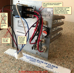
Why is the internal wiring in a 10 kW electric heat kit for an air handler so flimsy? The specs and instructions are quite clear - 40A heater current draw at 240 VAC, minimum circuit ampacity is 57 A (leading to either 6 ga or 4 ga branch wiring, depending on the type of wire and wire insulation), and maximum overcurrent protection 60 A (breaker).
But the wiring installed by the factory (Goodman) inside the heat kit itself looks positively flimsy - each hot lead (red and black) feeding the contactor looks to be no larger than about 14 ga.
How could this be, especially when compared to the branch circuit wiring? Those wires are not in the air stream, and therefore not cooled. Maybe because they're only less than a foot long?
@InspectApedia (Editor), The small input wires (L1 and L2) supplying the contactor input have no markings on them. The contactor outputs (T1 and T2) go to 2 parallel 5 kW heaters. Each heater has 12 AWG wires (with its insulation good for as high 105 degrees C) feeding its roughly 20A; this is in line with what I expect from ampacity tables.
But the small wires feeding both heaters at once (through the contactor) is what's puzzling.
[Ed. note] Image above is the corrected version as submitted by reader.
On 2022-12-08 by InspectApedia (Editor) - Why is the internal wiring in Goodman electric heat kit so flimsy?
@hillpc,
Thank you for the interesting question/opinion. You would expect Goodman manufacturing, producing an electric heat for an air handler, to comply with the requirements for UL listing of their product as well as building codes as well as having every intention of making their product safe. We can't see the wiring that you describe - do post some photos (one per comment) if you can.
We often see electrical wires routed through open space in an appliance, such as the wires to the heating elements in an electric clothes dryer. Properly-chosen the wire is rated to carry the current (amps) demanded by its application and to be safe, including using a wire with insulation rated to withstand the temperatures of its environment.
Take a very close look at those wires - if you can do so safely with power off - and note the letters, numbers and words describing the wire and its intended use.
On 2022-12-08 by InspectApedia (Editor) - smaller diameter wires are carrying just current to operate a control relay
@hillpc,
Thank you for the photo, question, discussion.
I SPECULATE that the smaller-diameter wires are carrying just current to operate a control relay that is switching the higher-current (larger) wires.
Check the wiring diagram.
On 2022-12-10 by hillpc
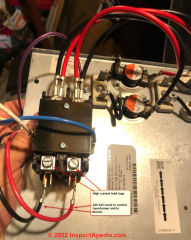
@InspectApedia (Editor), Thank you, you are correct. The actual high inlet current supply to the contactor is supplied by the inlet lugs on it (see pic; they are just like the outlet lugs for Romex on circuit breakers).
The flimsy black and red wires that I thought were inlets to the contactor are actually there to supply 240 VAC back to the control transformer and the blower. I'm so embarrassed. Please feel free to delete the post.
@InspectApedia (Editor), Here's an interesting observation on ampacity for this job. The Goodman instructions say to install supply wiring (to the input lugs) that's good for 57A (Minimum Circuit Ampacity). If Romex (NM-B), that's 4 AWG conductors (4-2 w/ground). I've found it difficult to find 4-2 w/ground Romex. 6-2 w/ground Romex is only good for 55A.
If I use THHN individual conductors (inside conduit) instead of Romex, I can get away with 6 AWG conductors. So I'm planning to put in a couple of 6 AWG THHN conductors (and a AWG 10 ground; appropriate size ground depends on the rating of the breaker) inside some conduit from the breaker panel.
On 2022-12-10 by InspectApedia (Editor)
@hillpc,
Actually your post and photos will be helpful to lots of other folks. Please try to talk yourself out of being embarrassed. I'm way ahead of most people in making mistakes. We learn more from mistakes than from getting it right the first time - as long as we survive the error.
On 2022-09-13 by Cindy - lost power in half of a Belmont mobile home doublewide - where are the wires & connectors?
1997 Belmont Home - 32x60 - lost 1/2 phase of power on one side. Where is the electrical run? In the walls or underneath? How to we find them to replace?
On 2022-09-13 by InspectApedia-911 (mod) - lost 1/2 phase of power on one side 1997 Belmont home
@Cindy,
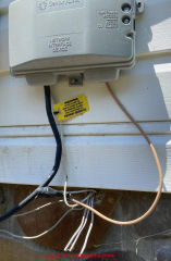
At this article MANUFACTURED HOME CROSSOVER CONNECTORS you'll find the typical locations of mobile home crossover connectors. A loose plug or connection at one of those is a common cause of losing power in half the home.
On 2022-08-03 by Josephine Kerns - phone connection inside doesn't work but outside the house it does
When I use the phone jack on the box outside the house, it works. But the two phone jacks I found in the house are "not connected to service". I have cleaned them out of dust and debris and the wiring appears sound. Can I solve this problem on my own?
On 2022-08-03 by InspectApedia-911 (mod) - find and fix a problem with phone wiring and jacks
@Josephine Kerns,
How to find and fix a problem with phone wiring and jacks.
Since we don't know anything about you I can't say if you can solve this phone wiring problem on your own, but in general, troubleshooting phone jack wiring problems is within the scope of many people - homeowners, renters, and users.
As long as you're ONLY fooling with phone wiring it's safe in that no high or dangerous voltages are involved.
The most likely reason that your phone would work when plugged into an outdoor phone jack but not work indoors is that one or more of those phone wires has become disconnected.
So start outside and note where the phone wires enter your building.
Find that location inside and find the entering phone wire.
Follow the wiring to each wiring splice or junction and inspect those carefully to see which wire connection has come apart.
Consider that while it's possible that phone wires running through hidden places like walls or ceilings might be damaged or cut (someone drives a nail to hang a picture and a nearby phone wire was not protected), that's not likely.
Instead, most phone wire problems occur at the connections. Those are usually visible in phone jacks or phone wiring junction boxes.
Since you have two indoor phone jacks and both are dead I suspect that the broken phone wire connection is at or ahead of the first phone jack.
Take a look, follow the wires, and let me know what you find.
On 2022-08-03 by Josephine
@InspectApedia-911, This is what I found:
On 2022-08-03 by InspectApedia (Editor)
@Josephine,
Okay that's a good start, so it looks like that beige colored wire is the telephone line going into your building.
Now see if you can find that on the inside of the wall at about that same location in the structure.
Then follow it.
On 2022-06-01 by Mike - wiring for surge protector at electrical panel?
I replaced my whole house surge protector on my 2 wire outside Main lug panel. I put the 2 black wires on the 20a double pole/throw breaker. I put the green & white in the common/ground bar. Is this a correct install?
On 2022-06-01 by InspectApedia-911 (mod)
@Mike,
I'm sorry because I really wish I could be helpful but I can't be confident that I can tell you what the correct wiring connections are with any assurance of safety for a system about which we have no information whatsoever.
On 2022-04-02 by Michael - missing strain reliefs on main panel - unsafe?
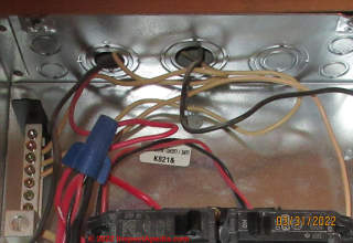
Electrical short-cuts, doing the right thing here would have cost less than $5. The feeds are floating in the hole at the top of the panel. I get amazed every day....
On 2022-04-02 by Inspectapedia Com Moderator - missing strain reliefs are signs of poor electrical work
@Michael,
Thanks for the excellent photo and the post of missing strain reliefs at an electrical panel.
I agree completely that it shows a shortcut indicating work by someone who's not a trained electrician and whose other wiring details might also be unsafe.
On 2022-03-09 by Anonymous - who can tell me the age of my electrical panel?
Who would i need to contact to find out when my electric panel was installed in my home?
On 2022-03-09 by Inspectapedia Com Moderator
@Anonymous,
Please see
ELECTRICAL PANEL AGE
where you'll see what clues people typically seek to make a reasonable guess at the age of an electrical panel.We look at panel type, size, labels, building age, wiring type, age etc.
On 2022-02-05 by Glenn - I need to verify the bus rating in a GTE Sylvania Zinsco electrical panel
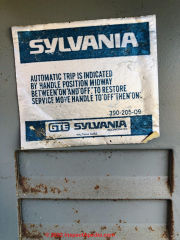
My question is I have a Sylvania zinsco type 100a main breaker panel 390-205-09 ( this is all the panel has for identification ) plus a label for the enclosure (BW-819527 )
I need to verify the bus rating of this panel, I am looking to get a solar system and want to use the existing panel, hopefully you can help with some info that I can print out for verification. My home is located in Rohnert Park CA 94928 and was built in 1980
Thanks
On 2022-02-05 by Inspectapedia Com Moderator - replace the Sylvania Zinsco panel
@Glenn,
I'm sorry to have to tell you that the AMPS rating for your electrical panel is IMO zero because it's a known fire hazard.
I don't mean to sound glib but the fact is you should replace the panel. Please read details at
ZINSCO SYLVANIA ELECTRICAL PANEL HAZARDS
...
Continue reading at ELECTRICAL DEFINITIONS or select a topic from the closely-related articles below, or see the complete ARTICLE INDEX.
Or see ELECTRICAL SYSTEM REPAIR FAQs - questions and answers posted originally at this page
Or see these
Recommended Articles
- ELECTRICAL DEFINITIONS
- U.S. CPSC HOME ELECTRICAL HAZARDS Publication No. 518 [PDF]
Suggested citation for this web page
ELECTRICAL INSPECTION, DIAGNOSIS, REPAIR at InspectApedia.com - online encyclopedia of building & environmental inspection, testing, diagnosis, repair, & problem prevention advice.
Or see this
INDEX to RELATED ARTICLES: ARTICLE INDEX to ELECTRICAL INSPECTION & TESTING
Or use the SEARCH BOX found below to Ask a Question or Search InspectApedia
Ask a Question or Search InspectApedia
Questions & answers or comments about building electrical systems, panels, breakers, wiring installation, inspection, diagnosis, & repair.
Try the search box just below, or if you prefer, post a question or comment in the Comments box below and we will respond promptly.
Search the InspectApedia website
Note: appearance of your Comment below may be delayed: if your comment contains an image, photograph, web link, or text that looks to the software as if it might be a web link, your posting will appear after it has been approved by a moderator. Apologies for the delay.
Only one image can be added per comment but you can post as many comments, and therefore images, as you like.
You will not receive a notification when a response to your question has been posted.
Please bookmark this page to make it easy for you to check back for our response.
IF above you see "Comment Form is loading comments..." then COMMENT BOX - countable.ca / bawkbox.com IS NOT WORKING.
In any case you are welcome to send an email directly to us at InspectApedia.com at editor@inspectApedia.com
We'll reply to you directly. Please help us help you by noting, in your email, the URL of the InspectApedia page where you wanted to comment.
Citations & References
In addition to any citations in the article above, a full list is available on request.
- Thanks to home inspector Larry Olson lomo5202@gmail.com for forwarding the 2010 US CPSC circuit breaker recall information concerning Siemens Murray equipment.
- [2] N. Srinivasan, MSEE, is a senior member of IEEE with 30 years experience in the electrical industry. Mr. Srinivasan is in Vienna VA.
- [3] Louis P. Babin generously contributed technical editing about the effects of doubling ampacity in an electrical circuit (September 2007)
- [4] Digisnap DSA-500 snap-around digital multimeter, A.W. Sperry Instruments Inc., 2150 Joshua's Path, Suite 202, Hauppage NY 11788, Tel: 800-645-5398, Email: cat@awsperry.com, Website: www.awsperry.com
- [5] Fluke Corporation, 6920 Seaway Blvd, Everett, WA 98203, USA, PO Box 9090 Everett, Washington 98206, Tel: +1(425) 347-6100, Technical support: 1(800) 44-FLUKE (1(800) 443-5853), Website: www.fluke.com,
Fluke Europe B.V, PO Box 1186 Eindhoven, The Netherlands, Tel: +31 (0)40 2 675 200 +31 (0)40 2 675 222, Website: www.fluke.eu - Fluke India: TTL India Pvt. Ltd. (A Fluke Company), Deodhar Center, 424, Marol Maroshi Road, Andheri (E), Mumbai, 400076, Tel: 1 800 209 9110, Email: info.india@fluke.com, Website: http://www.fluke.com/fluke/inen/products/Digital-Multimeters.htm
- Digital 287/289 Digital Multimeter, Users Manual, retrieved 9/5/21, original source: http://assets.fluke.com/manuals/287_289_umeng0200.pdf, [copy on file as Fluke_287_289_umeng0200.pdf]
- [6] Simpson Electric, P.O. Box 99, 520 Simpson Avenue, Lac du Flambeau, WI 54538-0099 Tel: 715-588-3311, customer service: 715-588-3947, Email: support@simpsonelectric.com, Website: www.simpsonelectric.com/
- Simpson 260® Series 6XLM Volt-Ohm-Milliammeter Instruction Manual, retrieved 9/5/2012, original source: http://www.simpsonelectric.com/uploads/File/datasheets/260-6xlm.pdf, [copy on file as Simpson_260-6xlm.pdf]
- [7]TIF 300cc Tic Tracer voltage detector, Tif Instruments Inc., 9101 NW 7th Avenue, Miami, Florida 33150
- [8] Greenlee® GT-16 adjustable voltage detector, Greenlee Textron Inc., Website: greenlee.com, Tel: 800-435-0786 , Email: echsupport@greenlee.textron.com,
- [9] Jensen VOMs, no longer available
- [10] Mastech VOMs and DMMs (made in China), Shanghai Hihua V&A Instrument Company, 881 Ye Cheng Road Jia Ding District, Shanghai 201821, China, Email: mastech@vip.sina.com, Tel: +86 21 69523164 +86 21 69523225, Website: http://www.mastech.com.cn/
- [11] Equus Multimeters by Innova, Equus Products, Inc., 17352 Von Karman Ave., Irvine, CA 92614, U.S.A., Tel: 714-241-6800, Website: http://www.equus.com/
- [12] Actron DMMs & VOMs, Website: http://www.actron.com/
- [13] ExTech DMMs & VOMs, ExTech Corp. a FLIR company, Extech Instruments Corporation, 9 Townsend West, Nashua, NH 03063, U.S.A., Email: support@extech.com, Tel: 877-239-8324 Option 3, Website: http://www.extech.com
- [15] Dr. Jess Aronstein, consulting engineer, Poughkeepsie NY, 1991 protune@aol.com
- [16] Rex Cauldwell, master electrician and contributor to the Journal of Light ConstructionOn electrical topics
- [17] New York State Central Hudson Gas and Electric Company, G&E/1-2/85 consumer safety pamphlet
- [18] Mark Cramer Inspection Services Mark Cramer, Tampa Florida, Mr. Cramer is a past president of ASHI, the American Society of Home Inspectors and is a Florida home inspector and home inspection educator. Contact Mark Cramer at: 727-595-4211 mark@BestTampaInspector.com 11/06
- [19] Roger Hankey is principal of Hankey and Brown Inspections, Winter Park, CO. Mr. Hankey is a past chairman of the ASHI Standards Committee and served in other ASHI chapter and national leadership roles. Mr. Hankey is a National Radon Proficiency Program certified measurement professional and a Level II infrared thermographer. Contact Roger Hankey at: 970-393-6604 - rogerhankey47@gmail.com . Website: www.HankeyandBrown.com Mr. Hankey is a frequent contributor to InspectAPedia.com.
- [20] Arlene Puentes [Website: www.octoberhome.com ] , an ASHI member and a licensed home inspector in Kingston, NY, and has served on ASHI national committees as well as HVASHI Chapter President. Ms. Puentes can be contacted at ap@octoberhome.com
- [21] ASHI Technical Journal, Vol. 2. No. 1, January 1992, "Determining Service Ampacity," Dan Friedman and Alan Carson, and the
- [22] ASHI Technical Journal, Vol. 3. No. 1, Spring, 1993, "Determining Service Ampacity - Another Consideration," Robert L. Klewitz, P.E., with subsequent updates and additions to the original text ongoing to 2/19/2006. Reprints of the originals and reprints of the Journal are available from ASHI, the American Society of Home Inspectors www.ashi.com.
- [24] "Electrical System Inspection Basics," Richard C. Wolcott, ASHI 8th Annual Education Conference, Boston 1985.
- [25] "Simplified Electrical Wiring," Sears, Roebuck and Co., 15705 (F5428) Rev. 4-77 1977 [Lots of sketches of older-type service panels.]
- [26] "How to plan and install electric wiring for homes, farms, garages, shops," Montgomery Ward Co., 83-850.
- [27] "Electrical System Inspection Basics," Richard C. Wolcott, ASHI 8th Annual Education Conference, Boston 1985.
- [28] "Home Wiring Inspection," Roswell W. Ard, Rodale's New Shelter, July/August, 1985 p. 35-40.
- [29] "Evaluating Wiring in Older Minnesota Homes," Agricultural Extension Service, University of Minnesota, St. Paul, Minnesota 55108.
- [30] Jim Simmons: Personal communication, J. Simmons to Daniel Friedman, 9/19/2008. Photographs contributed to this website by Jim P. Simmons, Licensed Electrician, 360-705-4225 Mr. Electric, Licensed Master Electrician, Olympia, Washington Contact Jim P. Simmons, Licensed Master Electrician, Mr. Electric, 1320 Dayton Street SE
Olympia, WA 98501, Ph 360-705-4225, Fx 360-705-0130 mrelectricwa@gmail.com - [31] Kenneth Kruger: Original author of the sidebar on testing VOM DMM condition: Kenneth Kruger, R.A., P.E. AIA ASCE, is an ASHI Member and ASHI Director in Cambridge, MA. He provided basis for this article penned by DJ Friedman.
- [33] LB Miller, "A simple Do-It-Yourself test fixture that will allow you to measure the DC resistance (Rm) of RC Model Electric Motors", San Marcos C, HobbyKing.com, retrieved 9/12/12, original source: http://www.rcgroups.com/forums/showthread.php?t=580151 [copy on file as Miller_Test.pdf]
- [34] "Electrical Systems," A Training Manual for Home Inspectors, Alfred L. Alk, American Society of Home Inspectors (ASHI), 1987, available from ASHI. [DF NOTE: I do NOT recommend this obsolete publication, though it was cited in the original Journal article as it contains unsafe inaccuracies]
- [35] "Basic Housing Inspection," US DHEW, S352.75 U48, p.144, out of print, but is available in most state libraries.
- [37] Andy Page, "The Basics of Motor Circuit Analysis", Reliable Plant, (Noria Corporation), 1328 E. 43rd Court, Tulsa, OK 74105
Tel: 800-597-5460; Email: pagea@alliedreliability.com, retrieved 9/13/12, original source: http://www.reliableplant.com/Read/10686/motor-circuit-analysis, [copy on file as THE BASICS of MOTOR CIRCUIT ANALYSIS [PDF] ] - Quoting:
MCA online [tests performed while the motor is operating] can be further split into two categories - current analysis and voltage analysis. Current analysis is primarily focused on the rotating components. Loose or broken rotor bars, cracked end rings, rotor eccentricity, misalignment and coupling/belt problems are some of the "big-hitter" failure modes detected in the current signature. Power quality issues like harmful harmonics, voltage imbalances and under/over-voltages are among the issues identified with voltage analysis.
MCA offline is most famous for the resistance-to-ground measurement. But other measurements make motor circuit defects easy to find. Measuring electrical characteristics like impedance, inductance and capacitance tell the analyst plenty about the condition of the windings. Inductance is a great indicator of turn-to-turn shorts. Capacitance to ground measures the amount of winding contamination (water, dirt, dust, etc.). Changes in each of these affect impedance (total resistance of an AC circuit). These characteristics are measured phase to phase and phase to ground and compared to each other and to percent change from baseline to identify motor circuit defects.
Motor circuit analysis (MCA) is often and easily confused with motor current analysis (MCA), which is an abbreviated version of motor current signature analysis (MCSA). - In addition to citations & references found in this article, see the research citations given at the end of the related articles found at our suggested
CONTINUE READING or RECOMMENDED ARTICLES.
- Carson, Dunlop & Associates Ltd., 120 Carlton Street Suite 407, Toronto ON M5A 4K2. Tel: (416) 964-9415 1-800-268-7070 Email: info@carsondunlop.com. Alan Carson is a past president of ASHI, the American Society of Home Inspectors.
Thanks to Alan Carson and Bob Dunlop, for permission for InspectAPedia to use text excerpts from The HOME REFERENCE BOOK - the Encyclopedia of Homes and to use illustrations from The ILLUSTRATED HOME .
Carson Dunlop Associates provides extensive home inspection education and report writing material. In gratitude we provide links to tsome Carson Dunlop Associates products and services.


