 Electrical Circuit Basics for Homeowners
- POST a QUESTION or COMMENT about electricity & residential electrical circuit basic concepts
Electrical circuits & short circutis, home electrical wiring basics & definitions:
This article answers basic questions about electricity and electrical wiring such as "What is an electrical circuit" and what is a "short circuit".
InspectAPedia tolerates no conflicts of interest. We have no relationship with advertisers, products, or services discussed at this website.
- Daniel Friedman, Publisher/Editor/Author - See WHO ARE WE?
What is an Electrical Circuit?
 Sketches at page top and at left are provided courtesy of Carson Dunlop Associates
[Click to enlarge any image]
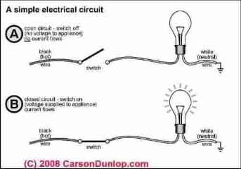
At the top of this page we show a very simple electrical circuit. Electrical energy (here very roughly defined as a flow of electrons) moves through a circuit to perform work such as lighting a light or heating a room.
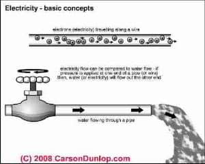
At left we show a common analogy using water flowing in pipes to help understand electrical circuits. Some people explain volts as similar to water pressure in a pipe, and amps as water current or total quantity flow. We discuss volts and amps below and in detail at this website.
A closed path of electron movement is required to put electrical energy into use.
This path is called a circuit. Sketch courtesy of Carson Dunlop Associates, a Toronto home inspection, education & report writing tool company [ carsondunlop.com ].
Every electric circuit has four basic parts:
- Electrical Energy Source - a source of electrical energy, AC (alternating current, used in most homes) or DC (direct current)
- Electrical conductors - electrical wires to carry electrical energy from its source to the point of use
- Electrical Load - an electrical device that uses energy such as a light bulb, computer, or electric heater
- Electrical Switches - controls to turn on or off electrical energy being supplied to an electrical load or device. In a home or other building electrical safety devices which protect the building from unsafe conditions such as a fire or electrical shock include circuit breakers or fuses which are really acting as an electrical "switch" to turn off electrical power should an unsafe condition occur.
Where does Electricity in a Building Come From?
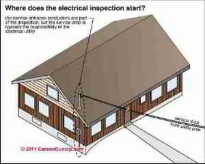
The real source electrical power at most buildings is an electric utility company which operates an electrical generator (a power station). The electric utility brings power from its power generators into a neighborhood where power is to be used by means of electrical transmission lines or power lines (big heavy wires).
For efficiency, electrical power is usually delivered into a neighborhood at very high voltage levels. In the neighborhood high voltage is converted by local power transformers (those big boxes or "cans" you see on some electric utility poles) to the lower voltage levels (240V or 120V) used in most buildings.
From the overhead (or in some communities buried) power transmission lines and transformer, a local power distribution wire (also overhead or buried) brings electrical power close to the building being served with power.
A service entry cable (SEC) (which is the responsibility of the building owner) connects the local power distribution wire to an electric meter mounted on or close to the building, and from the electrical meter, the service entry cable continues in to one or more main electrical panels on or inside the building. Sketch courtesy of Carson Dunlop Associates, a Toronto home inspection, education & report writing tool company [ carsondunlop.com ].
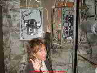
The electrical panel provides a place for mounting of fuses or circuit breakers which protect the building wiring from overheating and short circuits as a way to reduce fire risk. Inside of a building electrical power is distributed to various rooms through individual circuits, each of which is fed from the electrical panel(s).
However, for practical purposes, the source of electricity at an individual home or other building may be thought of as the circuit breaker panel or fuse box from which electrical power is distributed throughout a home or other building. Junction boxes and wall outlets may be thought of as secondary sources of electrical power since they convenient points at which a building occupant can connect electrical devices anywhere in a building.
See ELECTRICAL DEFINITIONS for definitions of "Volts", Watts, Amps, etc.
What are Electrical Conductors
Electrical Conductors are the wires that carry the electric energy to the point at which it will be used. Conductors offer little (but not zero) resistance to current flow because atoms in the metals they are made of have lots of free electrons and therefore can transport it efficiently.
What are the Definitions of Electrical Load, Amps, Watts
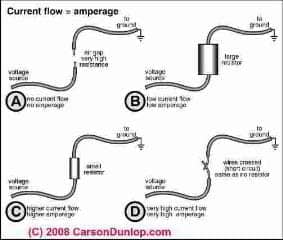
The electrical load is the amount of electrical energy that any device (a light bulb, your toaster or your washing machine, for example) uses to perform some work. The electrical load (unlike the electrical conductors) offers resistance to current flow.
This resistance makes it possible for the device to convert electric energy to another form (heat, light, mechanical movement, etc.).
The load resistance determines how much current will flow in a circuit. Increase the resistance in the load and you automatically decrease the current flowing in the circuit.
If the voltage applied to a circuit is multiplied by the current in amperes, the result is in units called watts. The watt is a unit of power and indicates the rate at which the load is consuming power.
The electrical load on a circuit is measured in Amps, a measure of electrical current.
See ELECTRICAL DEFINITIONS for detailed definitions such as "amps", "volts", and "watts". Sketch courtesy of Carson Dunlop Associates, a Toronto home inspection, education & report writing tool company [ carsondunlop.com ].
The Function of Electrical Switches
The fourth element in an electrical circuit is a means of controlling the energy. This is a device that can interrupt and restore current flow as desired by the user. Switches used in home electric systems control current flow by inserting a very high resistance (air gap) in the circuit to stop the current flow and by) removing the resistance (closing the air gap) to start current flowing again.
A basic principle of electrical wiring is that switches should always be wired into the hot (black or red) line leading directly to a device or outlet. When switches in the hot line are turned off, no hot line power is present in the load device. This greatly reduces the possibility of injury or damage resulting from accidental grounding.
What is an Electrical Short Circuit?
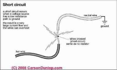
An electrical short circuit is a fault that occurs when a low resistance path exists between the hot lead and some grounded points.
When an electrical short circuit occurs, heavy current will flow in the circuit for as long as it takes for the circuit breaker to trip to OFF or for the fuse to blow.
Because a properly-working circuit breaker or fuse cuts off the current flow quickly, the circuit wiring will not have time to overheat to the point where fire may occur.
Sketch courtesy of Carson Dunlop Associates, a Toronto home inspection, education & report writing tool company [ carsondunlop.com ].
Safety Warning: an over-sized or improperly-installed fuse, and also some circuit breakers do not work reliably; a circuit breaker that is damaged by rust, corrosion, modification, or a circuit breaker which was poorly designed in the first place may not trip - resulting in a fire.
See FEDERAL PACIFIC FPE HAZARDS,
CIRCUIT BREAKER FAILURE RATES for some examples of problem circuit breakers.
What is an Open Circuit?
An open circuit is a fault that cuts off current flow in a circuit. The break that causes the open circuit may be in the hot line, the neutral line, or the load. An open circuit appears to be off. The break that causes an open circuit may be quite small. Vibration or even changes in temperature may suddenly turn the circuit on again. When looking for the cause of an open circuit, be sure power is off at the source.
Watch Out: Safety Warning: Do not attempt to work on your electrical wiring, switches, or outlets unless you are properly trained and equipped to do so. Electrical components in a building can easily cause an electrical shock, burn, or even death.
Even when a hot line switch is off, one terminal on the switch is still connected to the power source. Before doing any work on the switch, the power source must be turned off by setting a circuit breaker to OFF or removing a fuse.
See SAFETY for ELECTRICAL INSPECTORS
and ELECTRICAL WIRING BOOKS & GUIDES
What are the definitions of AC and DC Electrical Current?
The electrical energy that flows in circuits and operates loads can be generated in either of two different forms. One form is called alternating current (AC); the other form is called direct current (DC).
Alternating current is almost universally used for home electric power and is, therefore, the kind this article is primarily concerned with. In an AC circuit, the amount of voltage applied to the circuit is constantly changing from zero to a maximum and back to zero in one direction and then from zero to maximum and back to zero in the other direction. The maximum voltage is set by the generating plant.
Direct current is most commonly found in homes in the form of electrical energy stored in batteries. In a DC circuit, the amount of voltage and the direction of application are constant. The amount of voltage is determined by the type and size of battery. The direction of current flow is also constant and, as in AC circuits, the amount of current flow is determined by the load resistance.
DEFINITIONS of ELECTRICAL TERMS defines alternating current and direct current in more detail.
This website provides information about a variety of electrical hazards in buildings, with articles focused on the inspection, detection, and reporting of electrical hazards and on proper electrical repair methods for unsafe electrical conditions.
...
Reader Comments, Questions & Answers About The Article Above
Below you will find questions and answers previously posted on this page at its page bottom reader comment box.
Reader Q&A - also see RECOMMENDED ARTICLES & FAQs
On 2016-09-30 (mod) said: - Suggested basics of electrical wiring for kitchen designers
- Check the electrical codes or model code used in your jurisdiction for a detailed answer to your question and get to know your local electrical inspector - inspections that she makes protect you and your client from fire, shock, injury. It's smart to realilze you're on the same side.
- Typically we want to see at least two 20A circuits for electrical receptacles in a residential kitchen, with separate circuits for refrigerator, and for other major electrical appliances
- We are not going to be so stupid as to place an electrical receptacle too close to or over a sink or cooktop
- A smart kitchen electrical wiring setup will place quads of electrical receptacles in work locations where multiple small appliances are to be connected, splitting the quad across the two 20A circuits so that we can indeed plug appliances in where we want them and we can use them simultaneously without tripping the circuit breaker
- We provide GFCI protected electrical receptacles at the required locations such as close to sinks
On 2016-09-30 by Tracy
What are the basics in terms of residential applications should a kitchen designer knowOn 2016-07-30 by (mod) - what do you do with that red wire?
Anon:
As there are risks of electrocution and death for you messing with wiring, I'm nervous about pretending anyone can know for sure what wire is doing what in your system.
But typically if there is an un-used electrical wire terminating in an electrical box, it is capped off with a twist-on connector.
On 2016-07-30 by Anonymous
I am getting ready to install a light with ground, black and white wires. the line into the box has a ground, black, white and red wire. what should I do with the red wire?On 2016-03-17 by (mod) - how to keep the electrical receptacle "hot" when the switch is "closed" ?
Gil Just to keep our terms consistent, a "closed" switch means it is conducting power and an "open" one means it is not.
That nit picking over and done-with, you'll have to run a separate hot wire to your receptacle, as the switch is basically interrupting the hot line.
Examine the circuit, follow the wires. There may be an always-on "hot" already there, depending on how the switch was wired.
On 2016-03-17 by gil
I have a switch going to a light and to a plug receptacle, how can I keep the receptacle hot when the switch is closedOn 2016-01-10 by Kelvin
There was a junction box with three wires connected inside,two of the wires was connected black to white,/black to white and the third was connected to a wire that was coming out the junction box on one side and went back into it on the other.
Although the connection was working it seem to me this was incorrect. So I splice all three wires and connected the whites together,the blacks and the grounds,but when I engage the breaker it tripped. What could this problem be?
On 2015-06-30 by (mod) - can I used a single 110 v curcuit that is switched to 3 overhead lights
Sure, Lee, but you will most likely need to add switch wires from individual fixtures to individual wall switches.
On 2015-06-30 by lee
can I used a single 110 v curcuit that is switched to 3 overhead lights. can I use that circuit to run 2 switches and split how the lights come on. currently all the light come one with the singles switch . what I want is for two to operate from one stitch and the 3rd from a separate switch....
Continue reading at ELECTRICAL OUTLET ADAPTER SHORT CIRCUIT or select a topic from the closely-related articles below, or see the complete ARTICLE INDEX.
Or see these
Recommended Articles
- AFCIs ARC FAULT CIRCUIT INTERRUPTERS - reset an AFCI
- BLOWN FUSE REPLACEMENT
- CIRCUIT BREAKER MAIN or FUSE TEST
- ELECTRICAL CIRCUIT ID, MAP & LABEL
- ELECTRICAL DISTRIBUTION PANELS - common defects found by visual inspection
- ELECTRICAL INSPECTOR SAFETY PROCEDURES
- ELECTRICAL SYSTEM NOISES
- ELECTRICAL OUTLET ADAPTER SHORT CIRCUIT
- ELECTRICAL RECEPTACLE ARC PITTING
- ELECTRICITY TURN ON AFTER BREAKER TRIP - reset circuit breaker
- ELECTRIC POWER LOSS / FLICKERING LIGHTS
- GFCI TEST PROCEDURES - reset a GFCI
- MAIN ELECTRICAL DISCONNECT
- MOBILE HOME ELECTRICAL SYSTEMS
- MOBILE HOME ELECTRICAL - FLICKERING LIGHTS
- MOBILE HOME ELECTRICAL GFCI DIAGNOSIS
- MOBILE HOME ELECTRICAL POWER LOST
Suggested citation for this web page
ELECTRICAL CIRCUITS, SHORTS at InspectApedia.com - online encyclopedia of building & environmental inspection, testing, diagnosis, repair, & problem prevention advice.
Or see this
INDEX to RELATED ARTICLES: ARTICLE INDEX to ELECTRICAL INSPECTION & TESTING
Or use the SEARCH BOX found below to Ask a Question or Search InspectApedia
Ask a Question or Search InspectApedia
Try the search box just below, or if you prefer, post a question or comment in the Comments box below and we will respond promptly.
Search the InspectApedia website
Note: appearance of your Comment below may be delayed: if your comment contains an image, photograph, web link, or text that looks to the software as if it might be a web link, your posting will appear after it has been approved by a moderator. Apologies for the delay.
Only one image can be added per comment but you can post as many comments, and therefore images, as you like.
You will not receive a notification when a response to your question has been posted.
Please bookmark this page to make it easy for you to check back for our response.
IF above you see "Comment Form is loading comments..." then COMMENT BOX - countable.ca / bawkbox.com IS NOT WORKING.
In any case you are welcome to send an email directly to us at InspectApedia.com at editor@inspectApedia.com
We'll reply to you directly. Please help us help you by noting, in your email, the URL of the InspectApedia page where you wanted to comment.
Citations & References
In addition to any citations in the article above, a full list is available on request.
- Elizabeth Sluder, Montross, VA, the original author of this article [before extensive editing], is a public school teacher who writes basic educational articles about a variety of building, construction, and other topics. Her husband, a licensed electrician, consults for her writing on electrical topics. Her articles appearing at the InspectAPedia TM Website have been edited, illustrated, and on occasion content has been added by the website author. These articles are © 2010 InspectAPedia copyright-protected, all rights reserved.
- Mark Cramer Inspection Services Mark Cramer, Tampa Florida, Mr. Cramer is a past president of ASHI, the American Society of Home Inspectors and is a Florida home inspector and home inspection educator. Mr. Cramer serves on the ASHI Home Inspection Standards. Contact Mark Cramer at: 727-595-4211 mark@BestTampaInspector.com
- John Cranor [Website: /www.house-whisperer.com ] is an ASHI member and a home inspector (The House Whisperer) is located in Glen Allen, VA 23060. He is also a contributor to InspectApedia.com in several technical areas such as plumbing and appliances (dryer vents). Contact Mr. Cranor at 804-873-8534 or by Email: johncranor@verizon.net
- "Electrical System Inspection Basics," Richard C. Wolcott, ASHI 8th Annual Education Conference, Boston 1985.
- "Simplified Electrical Wiring," Sears, Roebuck and Co., 15705 (F5428) Rev. 4-77 1977 [Lots of sketches of older-type service panels.]
- "How to plan and install electric wiring for homes, farms, garages, shops," Montgomery Ward Co., 83-850.
- "Simplified Electrical Wiring," Sears, Roebuck and Co., 15705 (F5428) Rev. 4-77 1977 [Lots of sketches of older-type service panels.]
- "Home Wiring Inspection," Roswell W. Ard, Rodale's New Shelter, July/August, 1985 p. 35-40.
- "Evaluating Wiring in Older Minnesota Homes," Agricultural Extension Service, University of Minnesota, St. Paul, Minnesota 55108.
- "Electrical Systems," A Training Manual for Home Inspectors, Alfred L. Alk, American Society of Home Inspectors (ASHI), 1987, available from ASHI. [DF NOTE: I do NOT recommend this obsolete publication, though it was cited in the original Journal article as it contains unsafe inaccuracies]
- "Basic Housing Inspection," US DHEW, S352.75 U48, p.144, out of print, but is available in most state libraries.
- In addition to citations & references found in this article, see the research citations given at the end of the related articles found at our suggested
CONTINUE READING or RECOMMENDED ARTICLES.
- Carson, Dunlop & Associates Ltd., 120 Carlton Street Suite 407, Toronto ON M5A 4K2. Tel: (416) 964-9415 1-800-268-7070 Email: info@carsondunlop.com. Alan Carson is a past president of ASHI, the American Society of Home Inspectors.
Thanks to Alan Carson and Bob Dunlop, for permission for InspectAPedia to use text excerpts from The HOME REFERENCE BOOK - the Encyclopedia of Homes and to use illustrations from The ILLUSTRATED HOME .
Carson Dunlop Associates provides extensive home inspection education and report writing material. In gratitude we provide links to tsome Carson Dunlop Associates products and services.


