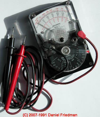
 How to Use a Digital Multimeter or DMM
Choosing a DMM,
Control settings on the DMM,
DMM features
- POST a QUESTION or COMMENT about how to use a digital multimeter; settings, features, procedures
How to use a digital multimeter or DMM. This article explains what a DMM or digital multimeter is, how to choose one, and the accuracy of DMMs.
We describe the typical DMM probe connections & control settings to make voltage measurements, resistance measurements, and current measurements. We also discuss the types of DMM protective circuits and safety features.
This article includes a table of typical DMM Functions, Ranges, & Accuracy Limits and a second table comparing the accuracy limits of DMM/VOM functions across most DMM/VOM manufacturer brands, using representative product models.
InspectAPedia tolerates no conflicts of interest. We have no relationship with advertisers, products, or services discussed at this website.
- Daniel Friedman, Publisher/Editor/Author - See WHO ARE WE?
How to Use a Digital Multimeter or DMM: choosing a DMM, control settings on the DMM, and DMM features
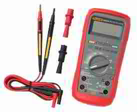 The following article was adapted from information provided courtesy of Fluke Corporation - India, used with permission. Contact Us to offer technical critique, suggestions, additions.
Watch Out: Home inspection standards for electrical inspections do not require the inspector to insert any instrument into the service panel.
Therefore electrical tests that require using a VOM or DMM are optional during a property inspection even if they are in fact necessary for other more in-depth troubleshooting.
See DMMs VOMs SAFE USE OF [separate article]
Opening an electrical panel and approaching live electrical wiring, devices, & equipment is a dangerous procedure that can damage electrical equipment or worse, cause electrical shock, or even death.
Such procedures should not be undertaken unless the person conducting the examination is trained and competent to avoid electric shock.
If the inspector is not trained for this procedure
s/he should never insert any instrument or tool into electrical equipment.
See SAFETY for ELECTRICAL INSPECTORS.
Our photo (above left) illustrates the Fluke 28 II DMM.
Detailed safety advice specially applicable to using VOMs, DMMs and ammeters, including both personal safety and advice to avoid damaging the equipment is found
at VOLTS / AMPS MEASUREMENT EQUIP
What is a Digital Multimeter or DMM?
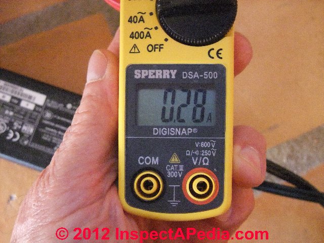
A DMM is simply an electronic device for making electrical measurements of electrical properties such as resistance, voltage level, or current flow.
A DMM may have any number of special features (such as the ability to measure and report decibels), but mainly a DMM measures AC or DC volts, ohms in one or more ranges, and amperes or electrical current.
Note: while the DMM settings described in this article were written to describe using a Fluke DMM, most digital multimeters will have very similar controls and will use similar measurement procedures.
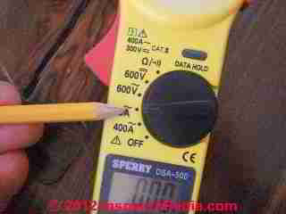
At left our photo illustrates the Sperry DSA-500 clamp-on multimeter/ammeter reading 0.28A (Amps) of current flow on an electrical circuit.
Accuracy of this measurement is as well as exactly how this measurement is made are discussed below.
Advice for Choosing a DMM
Choosing a DMM for the job requires not only looking at basic specifications, but also looking at features, functions, and the overall value represented by a meter’s design and the care taken in its production.
Reliability, especially under tough conditions, is more important than ever today.
[- Why? - Ed.]
Accuracy of Digital Multimeters (DMMs) and Analog VOMs
 Definition of multimeter accuracy: DMM accuracy is defined as the largest allowable error that will occur under specific operating conditions.
Accuracy for a DMM is usually expressed as a percent of reading. An accuracy of one percent of reading means that for a displayed reading of 100 volts, the actual value of the voltage could be anywhere between 99 volts and 101 volts.
At left our photo at left we illustrate measurement of Amps at 0.28A on the Sperry DSA-500 clamp-on multimeter/ammeter, the function dial has been set to the 0-40A range, the proper ampacity testing range in order to report with finer precision when measuring lower current levels than if we had used the 400A range setting.
But what about accuracy differences in different DMM measuring ranges?
Sperry's documentation for this DMM indicates that the accuracy of the instrument when measuring AC current (Amps) is +/- 2.0% rdg+/-6dgt when making measurements at 23+/-5degC and 45-75% relative humidity.
The company is in essence warning that at more extreme temperatures or humidity levels the accuracy of the instrument may vary from this level.
Details of the procedure for measuring amps are provided below at HOW to MAKE CURRENT MEASUREMENTS
Below we provide a table that describes the measuring ranges and accuracy of a DMM using this instrument as an example, followed by a table comparing DMM/VOM Specifications & settings for Actron DMMs, Equus / Innova DMMs, Extech Electronics DMMs, Fluke DMMs, Mastech DMMs, Simpson DMMs & VOMs, and Sperry DMMs.
Example Table of DMM Functions, Ranges, & Accuracy Limits 1 | ||
AC Current Measurements (Amps) Specifications |
||
| Amps Range Setting | Amps Measuring Range | Amps Measurement Accuracy |
| 40A | 0-39.99A | +/- 2.0% rdg +/-6dgt (50/60 Hz) |
| 400A | 0-399.9A | |
AC Voltage (V) Auto-Ranging 2 Specifications |
||
| AC Volts Range Setting | AC Volts Measuring Range | AC Voltage Measurement Accuracy |
| 400V | 0-399.9V | +/- 2.0% rdg +/-6dgt (50/60 Hz) |
| 600V | 150-599V | |
DC Voltage (V) Auto-Ranging 2 Specifications |
||
| DC Volts Range Setting | DC Volts Measuring Range | DC Voltage Measurement Accuracy |
| 400V | 0-399.9V | +/- 2.0% rdg +/-6dgt |
| 600V | 150-599V | |
Resistance Measurement Specifications (Ω / Continuity3 ) Auto-Ranging 2 |
||
| Ohms Function Setting | Ohms (Resistance) Measuring Range | Ohms Measurement Accuracy |
| 400Ω | 0-399.9Ω | +/- 2.0% rdg +/-6dgt |
| 4000Ω | 150-3999Ω | |
Notes to the table
1. This data describes and is adapted from specifications for the Sperry DSA-500 clamp-on multimeter/ammeter and reports data provided by that manufacturer. [4]
2. Auto ranging indicates that the instrument adjusts the digits of the display to suit the level being measured. For example, when the instrument is set to measure AC voltage level (3-green arrow in our photo at left), the device will automatically adjust its sensitivity range to report either 0-399.9V or 150-599V, depending on the voltage level that the instrument senses.
3. The instrument in ohms settings can be used as a simple electrical wire or circuit continuity tester. In this mode a buzzer beeps when resistance is measured as below 50Ω +/- 35Ω
Table Comparing Accuracy of Brands & Models of DMMs & Analog VOMs
| DMM Measurement Accuracy Specifications by Brand, Model, Parameter | ||||
|---|---|---|---|---|
| DMM Brand / Model 1 | AC Voltage Accuracy | DC Voltage Accuracy | Ohms Accuracy | AC Amps Accuracy 2 |
| Actron DMMs [12] CP7767 Automotive |
to 200V ±(0.8% rdg + 5 dgts) 750V ±(1.0% rdg + 4 dgts) |
to 200V ±(0.5% rdg + 5 dgts) 1000V ±(0.8% rdg + 5 dgts) |
to 2MΩ ±(0.8% rdg + 5 dgts) 20MΩ ±(1.5% rdg + 5 dgts) |
n/a |
| Actron CP 7849 Analog multimeter | not stated in product literature | not stated | not stated | not stated |
| Equus / Innova DMMs [11] 3320 |
±(1.2% of rdg + 5 digits) | ±(0.8% of rdg + 5 digits) | ±(2.0% of rdg + 5 digits) | ±(1.5% of rdg + 5 digits) only to 200 mA |
| Extech Electronics DMMs [13] EX330 DMM |
0.5% basic accuracy | 0.5% "basic accuracy" | 0.5% "basic accuracy" | 0.5% "basic accuracy" |
| EXMP530 DMM series | to 1000V ±(0.8%+3d) AC | to 5V ±(0.08%+2d) DC |
±(0.1%+2d) | ±(0.8%+4d) AC |
| EX542 True RMS DMM & Data Logger | 0.06% basic accuracy | 0.06% basic accuracy | 0.06% basic accuracy | 0.06% basic accuracy |
| Fluke DMMs [5] 28 II Ex |
±0.7 % +4 | ±0.05 % + 1 | ±(0.2 % + 1) | ±1.0 % + 2 |
| Fluke / 15B - 17B | ± (1.0 % + 3 counts) | ± (0.5 % + 3 counts) | ± (0.4 % + 2 counts) | ± (1.5 % + 3 counts) |
| Fluke / 289 True-rms | 0.4 %(true-rms) | 0.025 % | 0.05 % | 0.61 %(true-rms) |
| Fluke / 117 Electricians | 1.0 % + 3 (dc, 45 Hz to 500 Hz) 2.0 % + 3 (500 Hz to 1 kHz) |
± ([% of reading] + [counts]): 0.5% + 2 | 0.9 % + 1 low range 5 % + 2 high range |
1.5% + 3 |
| Mastech DMMs [10] VA19 |
± (0.8%+3digits) | ± (0.7%+3digits) | ± (0.8%+2digits) | ± (1.5%+3digits) |
| Mastech / VA20 | ±(1%+3) | ±(0.7%+2) | ±(1%+5) | ±(3%+10) |
| Mastech / MAS830 series | ±1.2% | ±0.5%~±0.8% | ±0.8%~±1.0% | n/a |
| Mastech / VA312 clamp on ammeter | ±(1.2%+5) | 6V/60V/600V ±(0.8%+5) |
to 6MΩ ±(1%+3) 60MΩ ±(5%+5) |
600A ±(2.5%+5) 1000A ±(3%+5) |
| Mastech / M266 clamp on ammeter | 750V ??.2% | 1000V ± 0.8% |
200Ω, 20KΩ±1.0% | 200 - 600A ±2.0%, 600 ~ 1000A ±3.0% |
| Simpson DMMs [6] 160 compact |
3% full scale | 2% full scale | 3 degrees of arc | n/a |
| Simpson / 260 6xLM | ± 3% full scale | ± 2% full scale | ±2.5° of an arc on the R X 1 range; ±2.0° of arc On all other ranges. |
n/a |
| Simpson / 270-5 | 2% of full scale @ 77oF 3% of full scale @67oF -87oF |
1.25% of full scale @ 77oF 1.75% of full scale @ 67oF - 87oF |
1.5o of arc on Rx1 1o of arc on all others |
n/a |
| Sperry DMMs [4] DM6200 |
2.5% + 5dgt | 200mV & 600V (1.2%+2dgt) 20V 200V (1.0%+2dgt) |
n/a | 200µ (1.5%+2dgt) 2K 20K 200K 2M (1.2%+2dgt) |
| Sperry / DM6600 | 40mv (1.2%+5dgt) 4V 40V 400V (1.0%+5dgt) 400mV 750V (1.2%+5dgt) |
40mv (1.2%+5dgt) 400mV (0.8%+3dgt) 4V 40V 400V (0.8%+1dgt) 1000V (1.0%+3dgt) |
400µA 4000µA (1.2%+2dgt) 40mA 400mA (1.5%+3dgt) 4A 10A (2.0%+3dgt) |
400 4M (1.2%+2dgt) 4K 40K 400K (1.0%+2dgt) 40M (1.5%+2dgt) |
| Sperry / 6650T True RMS | 40mV (1.2%+5dgt) 4V 40V 400V (1.0%+5dgt) 400mV 750V (1.2%+5dgt) |
40mV (1.2%+5dgt) 400mV (0.8%+3dgt) 4V 40V 400V (0.8%+1dgt) 1000V (1.0%+3dgt) |
400 4M (1.2%+2dgt)4K 40K 400K (1.0%+2dgt) 40M (1.5%+2dgt) |
400µA 4000µA (1.2%+2dgt) 40mA 400mA (1.5%+3dgt) 4A 10A Ω(2.0%+3dgt) |
| Sperry / DSA-500 | +/- 2.0% | +/- 2.0% | +/- 2.0% | +/- 2.0% |
| Sperry / DSA2009TMRS | 2.0% | 1%rdg, 2 dgt | 1.5% | 3dgt (0-1700A) 3.5% |
| Sperry /SPR300PLUS analog | +3% of FS | n/a | +3% of scale length | +3% of FS |
Notes to the table above
1. All DMM/VOM manufacturers produce a range of measuring instrument models with often different tolerances, functions, specifications, etc. This table quotes manufacturer's specifications but is not an exhaustive list of models nor model features.
2. Some of the DMMs or VOMs described here that do not provide AC current measurements do indeed provide DC current measurements - a feature not included in this table
What is the Difference Between Precision and Accuracy in DMM Measurements
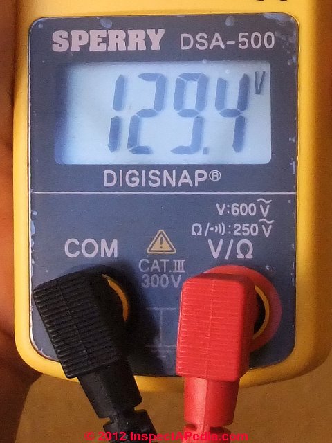 Watch out: don't confuse measurement precision with measurement accuracy. In the expression of measurements, precision refers to the number of decimal places or digits in a number obtained by the measurement, while accuracy describes the margin of error in the measurement.
People who do not understand this precision - accuracy distinction can be misled with regard to the reliability (accuracy) of numbers that are presented with much precision if the margin of error in the measurement was significant..
129.4 is a number that is less precise than 129.43939480
But if the possible range of error in our measurement is 10%, then our measurement of 129.4 OR our measurement of 120.2939480 both could be expressed as +/- 12 (since 12 is 10% of 120). This means that the range of accuracy of our measurement of 129.43939480 +/- 10% means that
at a 10% range of error (or for 129.4, +12.9V / - 12.9V)
the actual or "true" number could be anywhere between 133.43939480 and 108.43939480
which makes those extra decimal points meaningless.
To avoid presenting misleading results about the accuracy of our measurement, in most circumstances we would not report the measurement with all those decimal places. We would report 129.4 +/- 10%.
Watch out: don't confuse the accuracy of the DMM instrument itself and its individual readings with true measurement accuracy.
The DMM instrument and an individual measurement may be quite precise and quite accurate for conditions at the moment that the measurement was made. But external variables such as time, temperature, humidity, weather, voltage supplied by the electricity provider, electrical loads on the system and other factors mean that from one measurement to the next the results could be quite variable.
When measuring the voltage level of an electrical circuit in our office in Mexico we find that from time to time the actual voltage level can vary by about 10%. So while we might report that at a given measurement we measured the voltage level at 108V, that measurement should be presented as 108VAC +/- 10%, telling our client that over time voltage in that location typically varies between 98VAC and 118VAC (excluding periods of power loss when voltage is zero).
The true accuracy of an individual measurement as representative of the subject being measured over time may be quite different from the true accuracy of any individual (single moment of time) measurement instrument itself.
For further explanation of these sources of inaccuracy in various types of measurements,
see ACCURACY vs PRECISION of MEASUREMENTS.
How do I Connect Test Probes, Set Function, & Set Range When Using a DMM or VOM?
What is the Proper Connection of the Test Probes When Using a VOM or DMM?
By convention, all electrical test meters color their test probes: one probe is black, the other red.
- The black probe always is connected to the COM (common) input jack on the test instrument.
- The red probe is connected to a second appropriate input jack on the test instrument: V (volts) or ohms (Ω). On some instruments the V and Ω may be through a single input jack
- When disconnecting the multimeter or voltmeter, always unplug the red (hot) lead first.
What is the Proper Function Selection When Using a VOM or DMM?
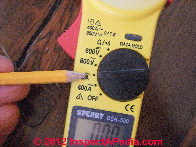 The Function setting on a VOM or DMM is usually a dial that selects among the basic functions of the instrument: measurements of Volts, Ohms, Amps or on occasion other features.
Watch out: be sure to select the proper function for the type of measurement being made. In particular, on some instruments, leaving the function selector set at Ohms ( Ω ) and then touching the probes to live AC or DC current may damage the instrument and may be unsafe.
In our photo the function dial is set to measure current (Amps) in the range of 0 to 40A. On this Sperry Instruments device there is an OFF position that should be used when the instrument is not in use or is to be stored.
Tip: for VOMs and DMMs whose function selector dial does not include an "OFF" position, when we are finished using the instrument we leave the selector set to AC-Voltage at the highest voltage range - a choice that minimizes risk of possible damage to the equipment should some fool touch the probes to live current without first checking the function dial position.
What is the Proper Range Selection When Using a VOM or DMM to Measure Volts or Amps?
If you are uncertain of the circuit properties you are measuring, or for general safety, always start a measurement at the highest range offered on the instrument.
Referring to our photo just above, for measuring AC voltage the highest voltage range would be the position indicated by the 3-green arrow. For measuring current or Amps the highest Amps range would be the position indicated by the 2-orange arrow.
Particularly on analog VOMs this step minimizes the risk of damage to the instrument or its meter movement assembly.
From this position and after reading the actual measurement obtained, if you see that the measurement is a much smaller number than the maximum range of the instrument, change the Range Selection to the next lower position, thus increasing the instrument's reporting sensitivity and precision.
How to make voltage measurements using a Digital Multimeter (DMM)
Select V~ (AC / alternating current) or V (DC / direct current), as appropriate for the electrical power source.
- Plug the black test probe into the COM input jack. Plug the red test probe into the V input jack.
- If the DMM has manual ranging only, select the highest voltage range so as not to overload the input.
- Touch the probe tips to the circuit across a load or power source (this places the DMM sensors in parallel to the circuit being tested).
- View the reading in Volts, being sure to note the unit of measurement.
For details of using a DMM or VOM to measure voltage,
For a description of electrical equipment used to detect or measure volts or amps
see VOLTS / AMPS MEASUREMENT EQUIP.
How to make resistance measurements (Ohms - Ω) using a Digital Multimeter (DMM)
- Turn off power to the circuit.
- Select resistance (Ω).
- Plug the black test probe into the COM input jack. Plug the red test probe into the Ω input jack.
- Connect the probe tips across the component or portion of the circuit for which you want to determine electrical resistance.
- View the reading, being sure to note the unit of measurement – ohms (Ω), kilohms (kΩ), or megohms (MΩ).
Note: 1,000 Ω = 1 kΩ
1,000,000 Ω = 1 MΩ
Watch out: Make sure the electrical power is off to the device or circuit being tested before making resistance measurements.
Tests of Electrical Motors by Measuring Resistance
DC electric motor resistance tests
Hobbyist LB Miller has described the design and function of a simple test fixture useful for determining the electrical resistance of DC motors by providing a 1A current to the motor and measuring the voltage drop across the motor, thus giving motor resistance in milli-ohms. Note that his approach is for DC motors. [33]
AC electric motor resistance tests
Testing an AC motor by measuring resistance across its windings or by making an apparently "simple" test of a motor (disconnected from all electrical power!) by measuring resistance across its power wires sounds appealing - as we might be able to deduce something about the condition of a motor that is itself not readily accessible, such as a submersible well pump located close to the bottom of a well.
We looked for some AC electric motor voltage, amps or current draw, and offline (power off/disconnected) electrical resistance measurement diagnostic rules of thumb. Unfortunately it's not quite so simple as motor types, designs, and specifications vary.
For details see ELECTRIC MOTOR DIAGNOSTIC GUIDE where we offline motor circuit analysis (MCA) test procedures that can through resistance (ohms) measurements identify shorted or open electric motor windings.
How to make current measurements (Amps) using a Digital Multimeter (DMM)
DMM Settings & Procedures for Making Current (Amps) Measurements
In-series amps compared with clamp-around or flexible probe Amps Measurements
- Turn off power to the electrical circuit
- Cut or unsolder the circuit, creating a place where the meter probes can be inserted
- Select V~ (AC / alternating current) or V (DC / direct current), as appropriate for the electrical power source.
- Plug the black test probe into the COM input jack. Plug the red test probe into the Amp or milliamp input jack, depending on the expected value of the reading.
- Connect the probe tips to the circuit across the break so that all current will flow through the DMM (the DMM is being connected in
series with the circuit being tested).
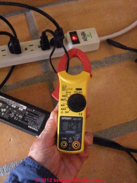 Our photo (left) does not illustrate this probe-in-series method for measuring amperage or current in an electrical circuit.
Rather, in our photo (left), a clamp-on digital ammeter is in use. A clamp-on ammeter woks on a different principle and does not require that test leads be used at all in order to measure current. Rather, the transformer jaws are clamped around one wire that forms part of the circuit being tested.Notice that the electrical wire was split so that the clamp-on ammeter's jaws surround just one of the two electrical wires. The transformer jaws or "clamp" must surround just one of the two 120V wires supplying the electrical device.
Also notice that we did not disturb nor damage the electrical wire insulation itself - doing so is dangerous and risks equipment damage or dangerous electrical shock as we cite just above.
Our photo (above-left) illustrates using Sperry's Digisnap DSA-500 - this is not a Fluke product.
Fluke also produces a range of clamp meters including the Fluke 376 that includes an interesting iFlex flexible current probe that extends the ability of the clamp-on ammeter to a wider range of circumstances and physical positions than the device we show here.
Fluke produces an i2500-10 iFlex™ kit that provides a variety of probes that extend ampacity measurements. - Turn the circuit electrical power back on.
- View the reading, being sure to note the unit of measurement.
Watch out: If the test leads are reversed for a dc measurement, a “–” will show in the display.
For examples of using a DMM to measure current,
In my photo above we are measuring the current draw in amps for the charging block of a laptop computer.
At the moment of our measurement this electrical device was drawing 0.29A at 120V.
For an accurate calculation of actual energy consumed that includes the effects of AC current and power factors,
see Definition of Power Factor, Real Power.
At ELECTRIC MOTOR DIAGNOSTIC GUIDE we describe both offline and online electric motor circuit analysis (MCA) test procedures.
Safety Features of Digital Multimeters (DMMs)
See DMMs VOMs SAFE USE OF for safety procedures to observe when using a digital multimeter.
Watch out: Common situations that lead to DMM failure:
- Contact with ac power source while test leads are plugged into current jacks.
- Contact with ac power source while in resistance mode.
- Exposure to high voltage transients.
- Exceeding maximum input limitations (voltage and current).
Types of DMM protection circuits
- Protection with automatic recovery. Some meters have circuitry that detects an overload condition and protects the meter until the condition no longer exists. After the overload is removed, the DMM automatically returns to normal operation.
- Protection without automatic recovery. Some meters will detect an overload condition and protect the meter, but will not recover until the operator performs an operation on the meter, such as replacing a fuse.
Look for these safety features in a DMM
- Fused current inputs
- Use of high-energy fuses (600 V or more)
- High-voltage protection in resistance mode (500 V or more)
- Protection against voltage transients (6 kV or more)
- Safety-designed test leads with finger guards and shrouded terminals
- Independent safety organization approval/listing (e.g., UL or CSA)
Article adapted from information provided provided courtesy of Fluke Corporation - India. Fluke offers a wide assortment of multimeters and has sales offices in most countries. Email: info.india@fluke.com
Explanation of CAT Ratings for Digital Multimeters
12 Januaryu 2015 Paul J. Ste. Marie said:
An important point you don't mention above is the CAT rating for the meter. This tells you the level of protection the meter provides from arc faults inside the meter and the type of circuits to which it can be safely connected. Cheap no-name import meters are not generally safe to connect to interior wiring, let alone distribution panels or service connections.
Reply:
Definition of CAT rating: the CAT rating or category rating of electrical test equipment describes its ability to withstand voltage spikes.
The 4 levels are cited below. Depending on your intended use of an electrical test instrument such as a digital multimeter, if for example you're checking residential electrical circuits, you probably do not need (and don't need to pay for) the highest rated CAT IV meter. Rather you probably want a CAT II or at most a CAT III rated meter.
Details of CAT ratings are in the UL standard UL 3111.1 Under this standard
- A CAT 1 (CAT I) electrical test meter rated for 150V is protected for spikes to 800V where V = voltage level. These meters are used on devices where high voltage is not expected such as tools measuring radio signals in communication equipment.
- A CAT 2 (CAT II) meter is typically used for measuring 120V or 240VAC equipment such as that used in buildings but might be damaged by voltage transients. This equipment is suitable for checking appliances or lighting circuits.
- A CAT 3 meter (CAT III) test meter is also designed for the type of circuit addressed by CAT 2 but is protected against voltage transients typical of those systems. These meters can be used to look at the electrical meter devices, branch electrical circuits in a building and 120V or 240V equipment in the building.
The meter's design presumes that there is a least one voltage-reducing transformer, such as one installed by the electrical utility company) between the circuits being tested and the high voltage wiring in the electrical utility distribution network. - A CAT 4 meter (CAT IV) has the highest level of electrical protection and is used by electricians working at power transformers; this equipment is also suitable for testing work on building electrical systems, underground feeders, HVAC compressor systems, well pumps, service entrance wiring.
- Citation: Electrical Construction & Maintenance, ecmweb.com, 9800 Metcalf Ave., Overland Park, Kan. 66212, retrieved 2015-01-10, - original citation ecmweb.com/archive/what-you-need-know-about-category-ratings
DMM & VOM Users Manuals & Sources
- Actron DMMs & VOMs, Website: http://www.actron.com/
ACTRON MULTIMETERS [PDF] specifications, CP7848 Analog multimeter, CP7848 - pocket electrical tester (analog), CP7605 - Dwell Tach Volt meter - ANALOG VOMs & MULTIMETERS
- AMPS MEASUREMENT AUTOMOTIVE DC
- AMPS MEASUREMENT METHODS
- DMMs VOMs SAFE USE OF Watch out: be sure to review this article before using a DMM or VOM
- ELECTRIC MOTOR DIAGNOSTIC GUIDE - home
- ELECTRICAL TOOLS BASIC
- Equus Multimeters by Innova, Equus Products, Inc., 17352 Von Karman Ave., Irvine, CA 92614, U.S.A., Tel: 714-241-6800, Website: http://www.equus.com/
- ExTech DMMs & VOMs, ExTech Corp. a FLIR company, Extech Instruments Corporation, 9 Townsend West, Nashua, NH 03063, U.S.A., Email: support@extech.com, Tel: 877-239-8324 Option 3, Website: http://www.extech.com
- Fluke Corporation, 6920 Seaway Blvd, Everett, WA 98203, USA, PO Box 9090 Everett, Washington 98206, Tel: +1(425) 347-6100, Technical support: 1(800) 44-FLUKE (1(800) 443-5853), Website: www.fluke.com,
Fluke Europe B.V, PO Box 1186 Eindhoven, The Netherlands, Tel: +31 (0)40 2 675 200 +31 (0)40 2 675 222, Website: www.fluke.eu - Fluke India: TTL India Pvt. Ltd. (A Fluke Company), Deodhar Center, 424, Marol Maroshi Road, Andheri (E), Mumbai, 400076, Tel: 1 800 209 9110, Email: info.india@fluke.com, Website: http://www.fluke.com/fluke/inen/products/Digital-Multimeters.htm
- FLUKE Digital 287/289 DIGITAL MULTIMETER USERS MANUAL [PDF] retrieved 9/5/21, original source: http://assets.fluke.com/manuals/287_289_umeng0200.pdf
- Greenlee® GT-16 adjustable voltage detector, Greenlee Textron Inc., Website: greenlee.com, Tel: 800-435-0786 , Email: echsupport@greenlee.textron.com,
- Jensen VOMs, no longer available
- Mastech VOMs and DMMs (made in China), Shanghai Hihua V&A Instrument Company, 881 Ye Cheng Road Jia Ding District, Shanghai 201821, China, Email: mastech@vip.sina.com, Tel: +86 21 69523164 +86 21 69523225, Website: http://www.mastech.com.cn/
- Simpson Electric, P.O. Box 99, 520 Simpson Avenue, Lac du Flambeau, WI 54538-0099 Tel: 715-588-3311, customer service: 715-588-3947, Email: support@simpsonelectric.com, Website: www.simpsonelectric.com/
- Simpson 160 VOM OPERATORS MANUAL [PDF] SIMPSON ELECTRIC COMPANY 520 Simpson Avenue Lac du Flambeau, WI 54538-0099 (715) 588-3311 FAX (715) 588-3326 Printed in U.S.A. Part No. 05-111658 Edition 16, 05/07 Visit us on the web at: www.simpsonelectric.com
- Simpson 260® Series 6XLM VOLT-OHM-MILLIAMMETER INSTRUCTION MANUAL [PDF], retrieved 9/5/2012, original source: http://www.simpsonelectric.com/uploads/File/datasheets/260-6xlm.pdf, [copy on file as Simpson_260-6xlm.pdf]
- TEST EQUIPMENT, ELECTRICAL GUIDE
- tif 300cc Tic Tracer voltage detector, Tif Instruments Inc., 9101 NW 7th Avenue, Miami, Florida 33150
- VOLTS / AMPS MEASUREMENT EQUIP
- VOLTS MEASUREMENT METHODS
InspectAPedia is an independent publisher of building, environmental, and forensic inspection, diagnosis, and repair information provided free to the public - we have no business nor financial connection with any manufacturer or service provider discussed at our website.
...
Reader Comments, Questions & Answers About The Article Above
Below you will find questions and answers previously posted on this page at its page bottom reader comment box.
Reader Q&A - also see RECOMMENDED ARTICLES & FAQs
Reader comments:
(Oct 6, 2012) Thommas said:
Is a very useful website.
Thanks.
(Jan 19, 2013) Ryan...License Electrician said:
I have looked ever were for some answers and I found this website 2 days ago and I have been on this website every evening for five to six hours last 2 days....I'm real good at troubleshooting control wiring systems...not much on checking motors,capacitors,and checking OHM,resistance but I do now...thank you so much...I can really get the understanding of what talking about...and I have tried to learn thanks again
Question: meter accuracy
(Apr 16, 2014) Pawan said:
±2.5° of an arc on the R X 1 range; ±2.0° of arc
On all other ranges.
What does this mean
And how to calculate it in terms of percentage.
Reply:
Depending on the meter type and its movement, such as an analog meter, the accuracy you describe may be referring to the arc of meter movement. If you tell us the brand and model of your multimeter we can give a more useful answer.
...
Continue reading at DMMs VOMs SAFE USE OF or select a topic from the closely-related articles below, or see the complete ARTICLE INDEX.
Or see these
Recommended Articles
Suggested citation for this web page
DMM DIGITAL MULTIMETER HOW TO USE at InspectApedia.com - online encyclopedia of building & environmental inspection, testing, diagnosis, repair, & problem prevention advice.
Or see this
INDEX to RELATED ARTICLES: ARTICLE INDEX to ELECTRICAL INSPECTION & TESTING
Or use the SEARCH BOX found below to Ask a Question or Search InspectApedia
Ask a Question or Search InspectApedia
Try the search box just below, or if you prefer, post a question or comment in the Comments box below and we will respond promptly.
Search the InspectApedia website
Note: appearance of your Comment below may be delayed: if your comment contains an image, photograph, web link, or text that looks to the software as if it might be a web link, your posting will appear after it has been approved by a moderator. Apologies for the delay.
Only one image can be added per comment but you can post as many comments, and therefore images, as you like.
You will not receive a notification when a response to your question has been posted.
Please bookmark this page to make it easy for you to check back for our response.
IF above you see "Comment Form is loading comments..." then COMMENT BOX - countable.ca / bawkbox.com IS NOT WORKING.
In any case you are welcome to send an email directly to us at InspectApedia.com at editor@inspectApedia.com
We'll reply to you directly. Please help us help you by noting, in your email, the URL of the InspectApedia page where you wanted to comment.
Citations & References
In addition to any citations in the article above, a full list is available on request.
- Daniel Friedman - Publisher & Editor of InspectAPedia.com®
- [2] N. Srinivasan, MSEE, is a senior member of IEEE with 30 years experience in the electrical industry. Mr. Srinivasan is in Vienna VA.
- [3] Louis P. Babin generously contributed technical editing about the effects of doubling ampacity in an electrical circuit (September 2007)
- [4] Digisnap DSA-500 snap-around digital multimeter, A.W. Sperry Instruments Inc., 2150 Joshua's Path, Suite 202, Hauppage NY 11788, Tel: 800-645-5398, Email: cat@awsperry.com, Website: www.awsperry.com
- [5] Fluke Corporation, 6920 Seaway Blvd, Everett, WA 98203, USA, PO Box 9090 Everett, Washington 98206, Tel: +1(425) 347-6100, Technical support: 1(800) 44-FLUKE (1(800) 443-5853), Website: www.fluke.com,
Fluke Europe B.V, PO Box 1186 Eindhoven, The Netherlands, Tel: +31 (0)40 2 675 200 +31 (0)40 2 675 222, Website: www.fluke.eu- Fluke India: TTL India Pvt. Ltd. (A Fluke Company), Deodhar Center, 424, Marol Maroshi Road, Andheri (E), Mumbai, 400076, Tel: 1 800 209 9110, Email: info.india@fluke.com, Website: http://www.fluke.com/fluke/inen/products/Digital-Multimeters.htm
- Digital 287/289 Digital Multimeter, Users Manual, retrieved 9/5/21, original source: http://assets.fluke.com/manuals/287_289_umeng0200.pdf, [copy on file as Fluke_287_289_umeng0200.pdf]
- [6] Simpson Electric, P.O. Box 99, 520 Simpson Avenue, Lac du Flambeau, WI 54538-0099 Tel: 715-588-3311, customer service: 715-588-3947, Email: support@simpsonelectric.com, Website: www.simpsonelectric.com/
- Simpson 260® Series 6XLM Volt-Ohm-Milliammeter Instruction Manual, retrieved 9/5/2012, original source: http://www.simpsonelectric.com/uploads/File/datasheets/260-6xlm.pdf, [copy on file as Simpson_260-6xlm.pdf]
- [7] tif 300cc Tic Tracer voltage detector, Tif Instruments Inc., 9101 NW 7th Avenue, Miami, Florida 33150
- [8] Greenlee® GT-16 adjustable voltage detector, Greenlee Textron Inc., Website: greenlee.com, Tel: 800-435-0786 , Email: echsupport@greenlee.textron.com,
- [9] Jensen VOMs, no longer available
- [10] Mastech VOMs and DMMs (made in China), Shanghai Hihua V&A Instrument Company, 881 Ye Cheng Road Jia Ding District, Shanghai 201821, China, Email: mastech@vip.sina.com, Tel: +86 21 69523164 +86 21 69523225, Website: http://www.mastech.com.cn/
- [11] Equus Multimeters by Innova, Equus Products, Inc., 17352 Von Karman Ave., Irvine, CA 92614, U.S.A., Tel: 714-241-6800, Website: http://www.equus.com/
- [12] Actron DMMs & VOMs, Website: http://www.actron.com/
- [13] ExTech DMMs & VOMs, ExTech Corp. a FLIR company, Extech Instruments Corporation, 9 Townsend West, Nashua, NH 03063, U.S.A., Email: support@extech.com, Tel: 877-239-8324 Option 3, Website: http://www.extech.com
- [15] Dr. Jess Aronstein, consulting engineer, Poughkeepsie NY, 1991 protune@aol.com
- [16] Rex Cauldwell, master electrician and contributor to the Journal of Light ConstructionOn electrical topics
- [17] New York State Central Hudson Gas and Electric Company, G&E/1-2/85 consumer safety pamphlet
- [18] Mark Cramer Inspection Services Mark Cramer, Tampa Florida, Mr. Cramer is a past president of ASHI, the American Society of Home Inspectors and is a Florida home inspector and home inspection educator. Contact Mark Cramer at: 727-595-4211 mark@BestTampaInspector.com 11/06
- [21] ASHI Technical Journal, Vol. 2. No. 1, January 1992, "Determining Service Ampacity," Dan Friedman and Alan Carson, and the
- [24] "Electrical System Inspection Basics," Richard C. Wolcott, ASHI 8th Annual Education Conference, Boston 1985.
- [26] "How to plan and install electric wiring for homes, farms, garages, shops," Montgomery Ward Co., 83-850.
- [30] Jim Simmons: Personal communication, J. Simmons to Daniel Friedman, 9/19/2008. Photographs contributed to this website by Jim P. Simmons, Licensed Electrician, 360-705-4225 Mr. Electric, Licensed Master Electrician, Olympia, Washington Contact Jim P. Simmons, Licensed Master Electrician, Mr. Electric, 1320 Dayton Street SE
Olympia, WA 98501, Ph 360-705-4225, Fx 360-705-0130 mrelectricwa@gmail.com - [31] Kenneth Kruger: Original author of the sidebar on testing VOM DMM condition: Kenneth Kruger, R.A., P.E. AIA ASCE, is an ASHI Member and ASHI Director in Cambridge, MA. He provided basis for this article penned by DJ Friedman.
- [33] LB Miller, "A simple Do-It-Yourself test fixture that will allow you to measure the DC resistance (Rm) of RC Model Electric Motors", San Marcos C, HobbyKing.com, retrieved 9/12/12, original source: http://www.rcgroups.com/forums/showthread.php?t=580151 [copy on file as Miller_Test.pdf]
- "Electrical Systems," A Training Manual for Home Inspectors, Alfred L. Alk, American Society of Home Inspectors (ASHI), 1987, available from ASHI. [DF NOTE: I do NOT recommend this obsolete publication, though it was cited in the original Journal article as it contains unsafe inaccuracies]
- "Basic Housing Inspection," US DHEW, S352.75 U48, p.144, out of print, but is available in most state libraries.
- In addition to citations & references found in this article, see the research citations given at the end of the related articles found at our suggested
CONTINUE READING or RECOMMENDED ARTICLES.
- Carson, Dunlop & Associates Ltd., 120 Carlton Street Suite 407, Toronto ON M5A 4K2. Tel: (416) 964-9415 1-800-268-7070 Email: info@carsondunlop.com. Alan Carson is a past president of ASHI, the American Society of Home Inspectors.
Thanks to Alan Carson and Bob Dunlop, for permission for InspectAPedia to use text excerpts from The HOME REFERENCE BOOK - the Encyclopedia of Homes and to use illustrations from The ILLUSTRATED HOME .
Carson Dunlop Associates provides extensive home inspection education and report writing material. In gratitude we provide links to tsome Carson Dunlop Associates products and services.


