
InspectAPedia® FREE Encyclopedia of Building & Environmental Construction, Diagnosis, Maintenance & Repair |
Question? Just ask us! InspectAPedia
|
 2-Wire (no ground) Electrical Outlet Wiring
How to wire an electrical plug outlet or wall plug when no ground wire is present or how to add a grounding conductor
- POST a QUESTION or COMMENT about how to install and 2 wire electrical outlets or receptacles in buildings.
How to wire an electrical receptacle ("outlet" or "wall plug") when there are just two wires (hot and neutral) but no ground wire.
This article explains that when there is no safe grounding conductor or "ground wire" at an electrical receptacle location, you need to choose the proper receptacle type and make the proper wire connections for safety.
This article series describes how to choose, locate, and wire an electrical receptacle in a home. Electrical receptacles (also called electrical outlets or "plugs" or "sockets") are simple devices that are easy to install, but there are details to get right if you want to be safe.
Watch out: if you are not trained in proper, code-legal, safe electrical wiring you should know that making a mistake can kill someone or set the building on fire. Better to get help from a licensed, trained electrician.
InspectAPedia tolerates no conflicts of interest. We have no relationship with advertisers, products, or services discussed at this website.
How to Hook up an Electrical Receptacle (wall outlet) on a Two-Wire Electrical Circuit
Here we discuss how to select & wire a two-wire ungrounded electrical receptacle when the electrical circuit has no grounding conductor.
We describe how to add a grounding conductor on older two-wire circuits that lacked an original grounding conductor, citing pertinent sections of the U.S. National Electrical code such as NEC Article 250.130 Equipment Grounding Conductor Connections.
[Click any image to see an enlarged, detailed view of electrical wiring details for "plugs" or electrical receptacles.]
We discuss how electricians address un-grounded receptacles or circuits by other approaches such as replacing the receptacle with a Ground-Fault Circuit Interrupters (GFCI) type receptacle or "wall plug".
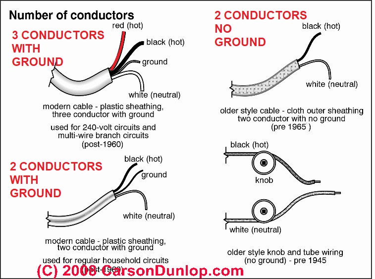
Watch out: as you see in the two illustrations at the left of our sketch, a circuit with a ground wire will present a bare or green-insulated wire and there will be three wires (or more) present.
We use the proper term electrical receptacle to describe the "wall plug" or "wall outlet" into which you will insert a two prong or three prong plug to connect an appliance, lamp, etc. Technically in the electrical code, an "outlet" is any place in where you provide a junction box and electrical wires to which something can be connected: a light fixture or an electrical receptacle, for example.
Article Contents
- ELECTRICAL CONNECTION for 2-WIRE RECEPTACLE CIRCUIT
- GFCI TESTING on UN-GROUNDED CIRCUITS (e.g. Knob & Tube) - separate article
Steps in Wiring an Electrical Receptacle on a Two-Wire Circuit (with no ground wire)
 Step 1: Recognize that the electrical circuit has just two wires and no electrical grounding conductor
In Carson Dunlop Associates' sketch above, the wire circuits shown at upper right and lower right are both two-wire electrical circuits where no ground wire is present.
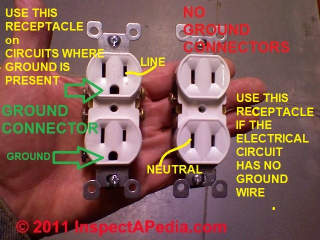
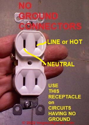
Shown again here is the correct type of electrical receptacle to use on these two-wire (no ground) circuits.
You will see that it has no connection opening for the ground-prong found on some wall plugs.
[Click to enlarge any image]
If no ground wire or ground path is provided, it is improper and unsafe to install a grounding (3-prong) electrical receptacle on that circuit.
Before doing any work on the switch, the power source must be turned off by setting a circuit breaker to OFF or removing a fuse.
See SAFETY for ELECTRICAL INSPECTORS
Step 2: buy the right type of electrical receptacle

Our photo shows, at left (green arrows) a conventional grounded three-prong electrical receptacle - the round hole is the ground connection.
At right in the photo is an ungrounded electrical receptacle. This is the right device to install if no ground is present on the electrical circuit.
You don't want to "fool" a building occupant into thinking that a ground is present when there is not one, so you don't install a receptacle that has that third ground opening in its face.
Watch out: If you are connecting an electrical receptacle to a wiring circuit that uses armored cable or "BX", the flexible metallic conduit exterior of BX cable is NOT a safe, usable pathway for electrical grounding.
Never don't rely on the flexible metal jacket of the BX cable to serve as an electrical ground.
That false-ground path is unreliable and unsafe, having to run through many physical connectors such as the BX cable clamp, metal boxes, and electrical receptacle mounting straps and screws.
And there is a hazard of electric shock: In event of certain short circuits the exposed metal sheathing of the wire becomes electrically-live, risking a shock that could injure or kill someone who touches the BX cable exterior.
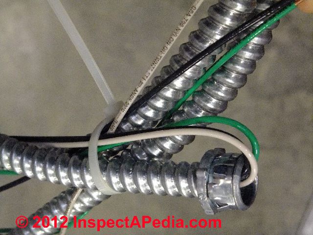
Photo above: modern armored cable or "BX" that includes a hot (black), neutral (white) and ground (green) wire. The metal jacket of this type of electrical cable is not itself a safe nor reliable electrical ground.
Our photo below shows just one of many ways in which BX armored cable or flexible metal conduit may be poorly connected or not even connected at all to a metal electrical receptacle box. The wiring show below is improper and unsafe and is an example of why the BX cable covering is not a true electrical ground.

Step 3: Wire the un-grounded electrical receptacle
So where do the wires go: to which screws on the electrical receptacle (shown just above) do we connect the black wire, white wire when there is no ground wire?
On a conventional 120-volt "two pronged" electrical outlet that accepts grounded plugs (two prongs plus the rounded center ground connector prong), your circuit will have three wires:
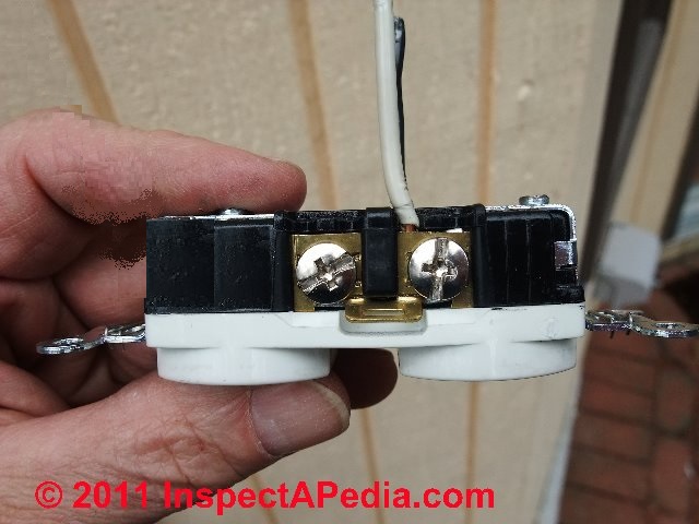
- The white "neutral" wire - this wire is connected to the silver screw on the electrical receptacle, often labeled "neutral".
You can see our white neutral wire connected to a silver screw on the receptacle in our photo above.
Below the photo shows the black or LINE or "HOT" wire connected to the brass-colored or darker terminal screw on the electrical receptacle.
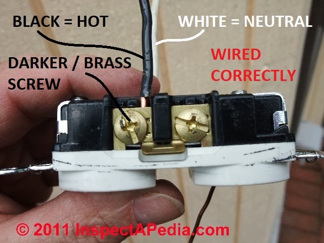
- The black "hot" wire - this wire is fed from the circuit breaker to deliver power to the receptacle, and it connects to the brass or bronze-colored screw on the receptacle, often labeled "hot" or "live".
You will see the hot black wire connected to the bronze or darker-colored screw on the receptacle shown above. The receptacle we used for these photos happens to be a 20-A rated device that permits the wire to be inserted straight into a clamp that is tightened against the wire by the screw.
Also see BACKWIRED ELECTRICAL RECEPTACLES
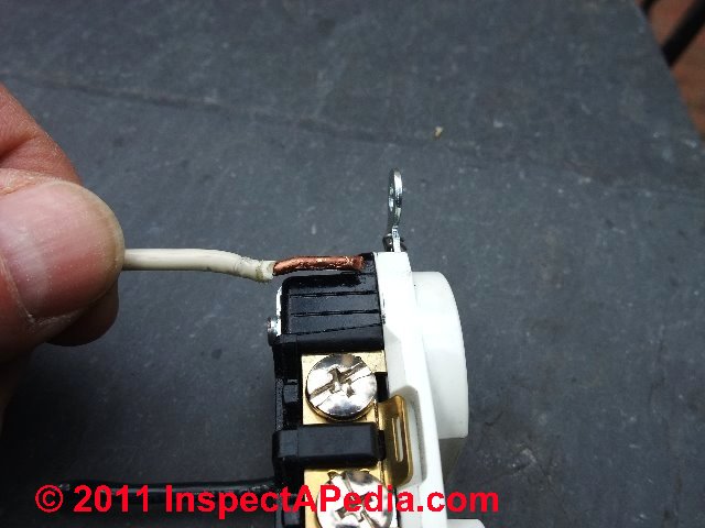
The photo below shows us comparing the stripped or bare copper wire length with the strip-gauge provided as an embossed detail in the plastic body of the receptacle.
- The missing ground wire - since a two wire circuit has no ground wire, you should have chosen an electrical receptacle that does not include an opening for the ground prong on a wall plug.
So the receptacle will not have a ground-wire connection screw or terminal.
If you had a ground wire, you'd use a grounding receptacle and the ground wire connects to the green ground screw usually found on the bottom of the electrical receptacle (sketch below left).
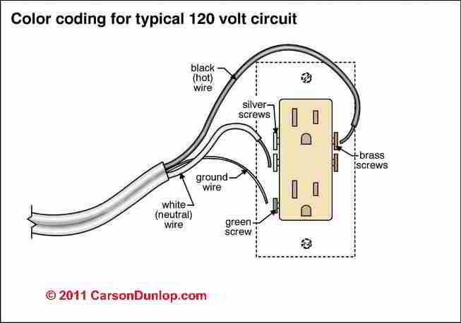
The illustration shows the typical wiring of a 3-wire electrical outlet or "receptacle", courtesy of Carson Dunlop Associates.
But remember that the typical wiring instructions for receptacles include a ground wire that may not be present on your circuit - as we explained just above.
Keep in mind that while a two-wire circuit may be permitted and "legal" in some jurisdictions, it is not as safe as an electrical circuit (and receptacle) that has a grounding conductor.
Don't Create a "False Ground" when Wiring a Receptacle
Watch out: Let's at least not make the un-grounded and two-wire circuit / electrical outlet even more dangerous by installing the wrong receptacle type. Installing a receptacle that includes a third opening for the wall plug's ground connector is dangerous if the circuit is not really grounded. Such a "false ground" means a false sense of safety that is not present.
Watch out: Electrical components in a building can easily cause an electrical shock, burn, or even death. If you are not trained in proper, safe electrical wiring it's best to hire someone who has that expertise.
Step 4 - Mount the Electrical Receptacle in the Box & Install the Cover Plate
The electrical receptacle must be properly screwed to or mounted in the junction box, and the extra length connecting wires carefully pushed back into the junction box so as to avoid crimping, damage, etc.
An electrical receptacle cover plate must be installed over the finished receptacle. We like plastic cover plates better than metal as they reduce the chances of a cover plate becoming electrically "live" and thus unsafe.
Avoid These Unsafe Practices When Wiring a 2-Wire (no ground) Receptacle Circuit
- Do not use a 3-wire type grounded electrical receptacle on a 2-wire ungrounded circuit
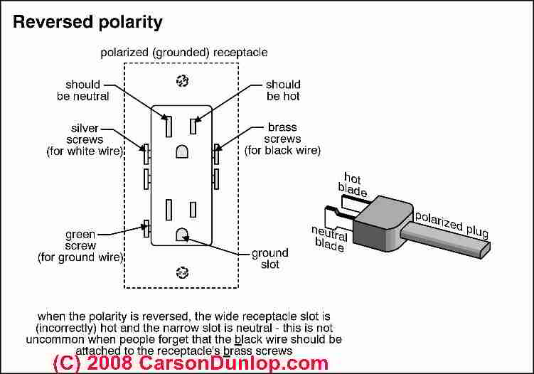
- Do not reverse polarity of the hot and neutral wires (discussed just below)
- Do not extend or add circuits, wires, or devices to an existing two-wire knob and tube electrical circuit.
- Watch out: while it is "legal" to add an electrical receptacle to an existing 2-wire circuit such as that shown at top right in our sketch above, it is not permitted to extend a knob-and-tube circuit (bottom right in the sketch) to add additional receptacles (or anything else) in most jurisdictions.
You can replace an existing damaged 2-wire receptacle in either circuit type but you should not extend or add receptacles and wires to an existing knob and tube circuit.
The hot and neutral wires must be connected to the proper terminals on the electrical receptacle. The "hot" or "live" black wire (or red wire) is connected to the brass-colored screw terminal on the electrical receptacle, and the "neutral" white wire is connected to the silver-colored screw terminal on the electrical receptacle.
Carson Dunlop Associates' sketch points out that the white wire, i.e. the neutral wire, will be connected through the receptacle's internal parts to the wide slot on the receptacle face in order to assure that the neutral wire side of an appliance being plugged-in there is properly connected.
Watch out: Reversed polarity on an electrical outlet is dangerous. If you accidentally reverse these wires, the device you plug in to the receptacle may "work" but it is unsafe and risks a short circuit, shock, or fire.
Details are
at REVERSED POLARITY ELECTRICAL DEVICES / CIRCUITS.
Some appliances and some electronic equipment may be damaged if left connected to a reversed-polarity electrical circuit.
- Do NOT connect circuit wires to the wrong terminals on the receptacle. Readers have proposed jumping the neutral to ground, for example. Don't do that - it's unsafe and illegal.
Can I Install a GFCI or AFCI Receptacle on a 2-Wire Electrical Circuit?
 Yes, with some additional steps such as proper labeling, and with some restrictions that we'll describe below, you can use a GFCI receptacle to replace an un-grounded receptacle on a 2-wire (no ground) older electrical circuit.
Generally, if installed on a 2-wire circuit that has no electrical ground conductor, a GFCI electrical receptacle will protect against a hot to neutral short or a hot to ground short at the receptacle but its internal test circuit cannot be used - that is, you can't easily test to know that the receptacle is working.
Label Un-Grounded Devices as No Equipment Ground
Watch out: do not ignore the NEC requirements (NEC Section 210-7) to LABEL the GFCI receptacle on a two-wire (un-grounded) circuit as
"GFCI Protected" and "No Equipment Ground."
Because some devices can be damaged if older style cord plugs are reversed on an un-grounded circuit and because some devices may depend on electrical grounding for safety, in my OPINION a better approach would be to put a GFCI breaker in the panel serving the circuit and to use only 2-prong electrical outlets on a two-wire circuit.
That adds GFCI protection while at the same time it prevents fooling people into thinking that the circuit has a ground.
U.S. National Electrical Code NEC 406.3 Permits GFCI receptacles to replace two-prong grounded outlets
Thanks to NECreader who commented on 2016/06/13:
This article states that NEC 406.3 permits GFCI receptacles to replace two prong ungrounded outlets. Here are some details.
(3) Non–Grounding-Type Receptacles.
Where attachment to an equipment grounding conductor does not exist in the receptacle enclosure, the installation shall comply with (D)(3)(a), (D)(3)(b), or (D)(3)(c).
(a) A non–grounding-type receptacle(s) shall be permitted to be replaced with another non–grounding-type receptacle(s).
(b) A non–grounding-type receptacle(s) shall be permitted to be replaced with a ground-fault circuit interrupter type of receptacle(s).
These receptacles shall be marked "No Equipment Ground."
An equipment grounding conductor shall not be connected from the ground-fault circuit interrupter-type receptacle to any outlet supplied from the ground-fault circuit-interrupter receptacle.
(c) A non–grounding-type receptacle(s) shall be permitted to be replaced with a grounding-type receptacle(s) where supplied through a ground-fault circuit interrupter.
Grounding-type receptacles supplied through the ground fault circuit interrupter shall be marked "GFCI Protected" and "No Equipment Ground." An equipment grounding conductor shall not be connected between the grounding type receptacles.
Un-Grounded Circuit + GFCI Is Not Adequate for Some Installations
Watch out: you should not rely on GFCI protection alone and thus you should not install an un-grounded receptacle (even with a GFCI) on a 2-wire circuit (no ground present) if that circuit is intended to supply cord- and plug-connected equipment that itself requires grounding. For example, in hospitals and nursing homes where such equipment requiring grounding is common, you simply would not use an un-grounded circuit.
This more nuanced explanation was given by OSHA in an interpretation of electrical grounding requirements for nursing homes (OSHA Standard No. 1910.304(f)(5)(v)1910.304(a)(3), Memorandum 21 December 1999). See details in
- ELECTRICAL GROUNDING REQUIREMENTS for EQUIPMENT CONNECTED by CORD and PLUG [PDF] Richard E. Fairfax, Directdor, OSHA Standard No. 1910.304(f)(5)(v)1910.304(a)(3), Memorandum 21 December 1999, U.S. Department of Labor, OSHA, Grounding Requirements for Equipment Connected by Cord and Plug [in nursing homes], retrieved 2022/03/11, original source: https://www.osha.gov/laws-regs/standardinterpretations/1999-12-21
Excerpt: OSHA is not allowing the use of a GFCI alone to protect employees using cord and plug connected equipment when such equipment is required to be grounded.
Paragraph 1910.304(f)(5)(v)(a) through (c), describes the types of cord and plug connected equipment, such as refrigerators and microwave ovens, that is required to be grounded with an equipment grounding conductor.
Arc fault protection - Arc-Fault Circuit Interrupters (AFCI) on Un-Grounded Circuits
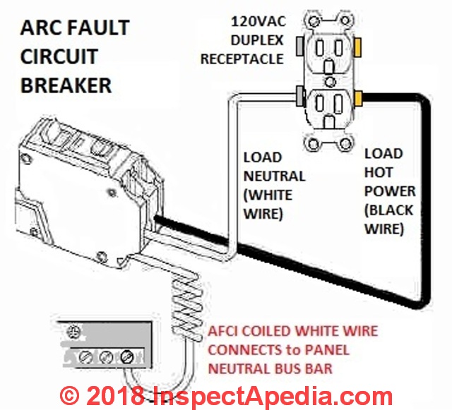 Beginning in 2002 the NEC also required arc fault protection for electrical outlets for bedrooms. [4]
AFCI's are similar to GFCI's discussed above, but they include an additional level of protection against fire by detecting small electrical arcing at a connection - a condition that can lead to overheating and fire.
As you can see from this sketch, you can add Arc fault protection to a home circuit by installing a special circuit breaker in the electrical panel.
By this means you can provide arc fault protection and thus improved fire safety for all electrical outlets on the circuit - for example in the building's bedrooms.
See AFCI GFCI WIRING, TESTING & SAFETY
and AFCIs ARC FAULT CIRCUIT INTERRUPTERS for details about these devices.
Bottom line on Methods for Updating Receptacles or Providing Grounding on an Older 2-wire Circuit
- Install GFCIs - Current electrical codes permit installing a GFCI protected electrical receptacle on an un-grounded circuit, with some labeling requirements and some circuit use restrictions that we describe above on this page.
- Add a grounding conductor - Current electrical codes permit adding a properly sized, routed, connected, protected grounding conductor.
- Don't install a 3-prong receptacle on a 2-wire circuit that has no ground.
- Don't rely on the BX metallic jacket to serve as a ground path back to the electrical panel.
- Don't rely on a "daisy-chained" ground system such as a grounding conductor wire screwed just to the box, a second ground wire screwed from the receptacle green ground screw then connected to another threaded junction box location, etc.
Bond the grounding conductors together and where a metal box is installed, also include a wire that connects the box to the grounding conductor. - Electrical Code compliance - Any alternative local ground installation used to provide a true grounding conductor for a 2-wire circuit would have to be code compliant throughout its design, route, and components.
- Costs of grounding vs re-wiring - It seems to me that the trouble, time, and cost of installing custom, properly wired new ground pathways connecting to each individual electrical box in an old 2-wire powered circuit might be higher than the cost to simply run a new 3-wire circuit throughout.
Is it Safe to Use a 3-Prong Adapter to Connect a 3-Pronged Appliance or Equipment Cord to a 2-Prong Ungrounded Electrical Outlet?
No, not really. If plug-connected equipment requires an electrical ground, your ground connection through the adapter is unreliable and thus unsafe. See details
at ELECTRICAL WALL PLUG ADAPTERS
How to Add a Ground to a 2-Wire Electrical Receptacle Circuit
 On 2020-06-18 (mod) - how to add a ground on the second floor when there is none
Barry
You would be sure that all receptacles are 2-slot without ground slot type. The NEC does not require you to add a ground but, that said,
I'm doubtful that there is actually "no way" to add an electrical ground wire to the receptacles or other fixtures as needed.
It may be more trouble but it seems likely that an electrician could either snake a suitably sized grounding conductor to the second floor and route it to where it's needed, or in worst case, run a suitably protected ground on the building exterior.
[Click to enlarge any image]
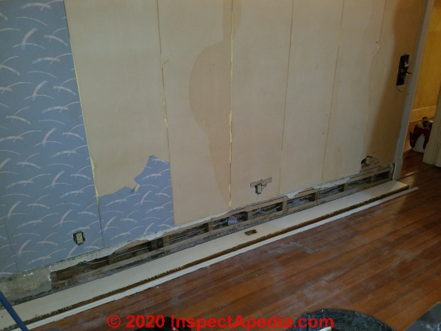
I've successfully added ground wiring (and wires for more receptacles) in older homes by pulling off the baseboard trim along the floor, running my new wires, protecting with nail plates at studs, then restoring the baseboard.
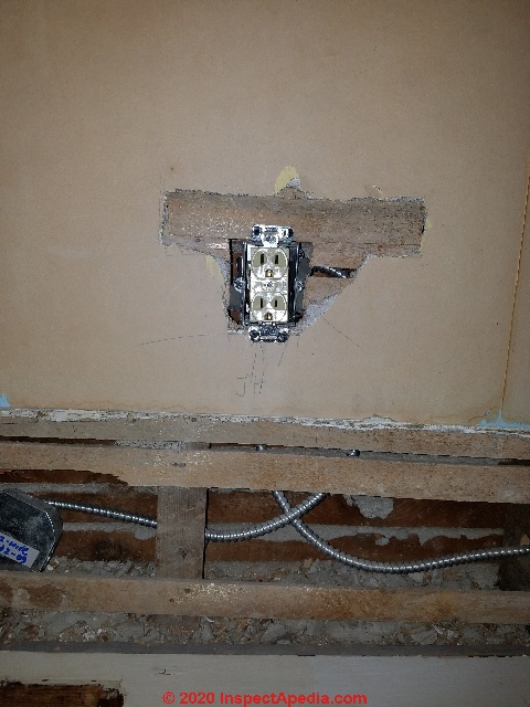
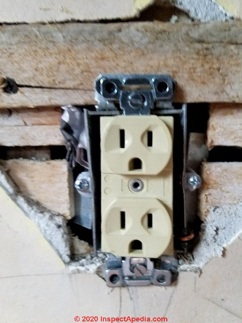
Below is an example from a renovation we did in 2016 in Poughkeepsie NY - before painting and refinishing room surfaces we pulled the baseboard trim and ran 12-2 w/ground BX (armored cable) to provide grounded receptacles in a room of a home built ca 1910.
Here's a closer look:
 ...
... 
See details at ELECTRICAL OUTLET, HOW TO ADD in OLDER HOME
On 2020-06-18 by Barry Bechtel - No way to run ground in 2nd story. What must I do?
Older home no ground wire FHA requirements for sale of house. No way to run ground in 2nd story. What must I do?
On 2017-08-08 by Dave - it legal to run a new single ground wire from the new outlet back to the breaker box ?
When converting an old 2 prong outlet to a new 3 prong (grounded) outlet - is it legal to run a new single ground wire from the new outlet back to the breaker box ground bar?
I.E. not replacing the existing BX wire. With that same thought - if there are multiple new 3 prong outlets - do they all need run all the way back to the breaker box ground bar?
Or can the multiple outlets be branched off a main feeder wire back to the breaker box ground bar?
This question was posted originally at GROUND WIRE CONNECTIONS
Reply:
In principle nothing precludes you running a new added ground wire from the breaker box to the receptacle to upgrade to 3-prong receptacles
Bottom line: Yes you can do what you describe. But there may be easier places to connect the new grounding conductor that I'll describe.
Current U.S. National Electrical Code 250.130(C)(1) and 250.130(C)(4) permit you to run a new grounding conductor wire OR to connect to an existing circuit grounding conductor.
A non-grounding type receptacle can be replaced with a grounding type receptacle if an equipment grounding conductor is installed and connected to any accessible point on the grounding electrode system.
OPINON: to me this reads that you don't have to run a wire all the way back to the panel IF you have a properly wired grounding electrode wiring system access point that's closer. An example would be a nearby 3-wire circuit that includes a properly sized, routed, and connected grounding conductor already installed.
Watch out: most electricians would just run a whole new wire (hot, neutral, ground) from the panel. I don't think that's just to gouge the client's wallet. It's because nobody who appreciates the reasons for the NEC - avoiding fire, shock, death - wants to bet their home and savings on unknown work and unknown wiring conditions in an existing house where they didn't do the earlier work.
You probably have also read of a different option: installing a GFCI receptacle; you can't test that the GFCI is really working - since its test button just tests an internal circuit - without grounding its hot and neutral to a real ground somewhere, but that's a legal alternative some electricians use.
Watch out also: some electricians rely on using the external metal jacket of some BX wiring (that includes a "bonding strip" an internal flimsy wire that pretends to give continuity to the cable sheath) but that is in my view dangerous - the jacket is not intended as a conductor, its connections over the circuit depend on clips at each metal box that in turn depend on both a screw and a nut both of which may be loose, and I've seen people shocked by touching the jacket when a fault was also present.
Here is the current, pertinent U.S. electrical code that discusses adding a grounding conductor on previously non-grounded receptacles or branch circuits.
Article 250 - Grounding and Bonding
VII. Methods of Equipment Grounding
250.130 Equipment Grounding Conductor Connections. Equipment grounding conductor connections at the source of separately derived systems shall be made in accordance with 250.30(A)(1). Equipment grounding conductor connections at service equipment shall be made as indicated in 250.130(A) or (B).
For replacement of non–grounding-type receptacles with grounding-type receptacles and for branch-circuit extensions only in existing installations that do not have an equipment grounding conductor in the branch circuit, connections shall be permitted as indicated in 250.130(C).
(C) Nongrounding Receptacle Replacement or Branch Circuit Extensions. The equipment grounding conductor of a grounding-type receptacle or a branch-circuit extension shall be permitted to be connected to any of the following:
(1) Any accessible point on the grounding electrode system as described in 250.50
(2) Any accessible point on the grounding electrode conductor
(3) The equipment grounding terminal bar within the enclosure where the branch circuit for the receptacle or branch circuit originates
(4) To an equipment grounding conductor that is part of another branch circuit that originates from the enclosure where the branch circuit for the receptacle or branch circuit originates
(5) For grounded systems, the grounded service conductor within the service equipment enclosure.
(6) For ungrounded systems, the grounding terminal bar within the service equipment enclosure
Electrician's views on how to protect or ground 2-wire circuits and un-grounded or non-grounding receptacles in older buildings
I looked at several electrician's comments in forums and at electrical code interpretations for add-on grounding conductors for un-grounded 2-wire circuits and receptacles:
US NEC 210-7(d) - excerpting [in italicized text]
Replace a nongrounding-type receptacle with a grounding-type if there is an equipment grounding conductor available and connect the grounding conductor.
If there is no equipment grounding conductor then replace with a nongrounding-type receptacle or a GFCI type that is marked "No Equipment Ground," or a grounding type if it is protected by a GFCI and marked "GFCI Protected" and marked "No Equipment Ground.
An equipment grounding conductor shall not be connected from the GFCI receptacle that does not have an equipment grounding conductor to any other outlet supplied by the GFCI receptacle, and an equipment grounding conductor shall not be connected between grounding-type receptacles that are protected by a GFCI type receptacle that has no equipment grounding conductor.
- which is not what you want to do anyway. You want to add a grounded or "three-prong" electrical receptacle where an older un-grounded "two prong" receptacle was wired to a 2-wire circuit that has no grounding conductor.
For a 15 or 20 ampere circuit code experts point out that in a retrofit to add a grounding conductor you are permitted to run a No. 12 copper that is bare or green or green with one or more yellow stripes by itself so as not to be subject to physical damage from the receptacle grounding terminal to the grounding electrode as described in 250-81 or, after the 1996 NEC is adopted, to any accessible point on the grounding electrode grounding conductor .
US NEC 110-12 requires that electrical work be performed in a neat and workmanlike manner.
10.12. Mechanical Execution of Work.
Electrical equipment shall be installed in a neat and workmanlike manner.
That general remark means the on-site electrician decides where and how to run the wire, but when workmanship is proper, along with
NEC 300.4 Protection Against Physical Damage,
that includes protection from damage.
And all of this presumes that once the ground is provided you are going to install a grounded-type electrical receptacle.
Next I looked at Article 300 that describes running wires.
300.3 Conductors. (A) Conductors. Conductors must be installed within a Chapter 3 wiring method, such as a raceway, cable, or enclosure. This seems to say you cannot run an isolated grounding conductor wire outside of the enclosure of the hot and neutral wires.
BUT
NEC 00.3.B (2) Grounding and Bonding Conductors.
Equipment grounding conductors can be installed outside of a raceway or cable assembly for certain existing installations. See 250.130(C). Equipment grounding jumpers can be located outside of a flexible raceway if the bonding jumper is installed in accordance with 250.102(E).
That looks like help but it actually pertains to short runs up to 6 ft. for adding a ground taped to the BX wires feeding an electric motor (for example). See 250.130(C)
That leads to
Section 250.130(C) allows a grounding-type receptacle to be used as a replacement, instead of a GFCI protected outlet, if the equipment grounding terminal of the receptacle is connected to an acceptable grounding means.
In the 2011 NEC, the grounding terminal of a replacement receptacle used in a two wire system could be connected to the grounding electrode system, the grounding electrode conductor, or the equipment grounding terminal bar in the same enclosure where the branch circuit for the receptacle originates.
A new option for connecting the grounding terminal of a replacement receptacle has been added in 2014. Now an equipment grounding conductor that is part of another branch circuit that originates in the same panelboard as the branch circuit for the receptacle can be used to provide a grounding means for the replacement receptacle.
The new option is similar to the permission to connect the replacement receptacle grounding screw to the equipment grounding terminal bar in the enclosure where the branch circuit for the receptacle originates. However, it could be much easier to connect to an equipment grounding conductor from another branch circuit than to install a new equipment grounding conductor all the way back to the panelboard.
Reader Comments, Questions & Answers About The Article Above
Below you will find questions and answers previously posted on this page at its page bottom reader comment box.
Reader Q&A - also see RECOMMENDED ARTICLES & FAQs
Reader Question: several people suggested it would be possible to ground to the box using a grounding screw
I was reading your sections on grounding on older home as I am currently in the process of having several two-prong outlets upgraded. In my research, several people suggested it would be possible to ground to the box using a grounding screw.
I didn't go that route but was looking to see what your site had to say about the practice. I was disappointed to find out it wasn't even mentioned. Is there anything you can say, is it a safe practice? - Thanks. K.B. 8/5/13
Reply:
Thanks so much for the question - in the article above and elsewhere I have mentioned the problem of the missing ground wire on a two-wire circuit and also the problem of unreliable ground connections through the receptacle mounting strap screw - but your question helps me see that I must not have made the point clear and easy enough to find.
When you are replacing electrical receptacles ("outlets") in an existing two-wire (hot, neutral, no ground) circuit that is in good physical condition, the only recommended and code-approved solution (short of re-wiring) that I have found is to install new two-slot (no ground prong opening) electrical receptacles in the box. [I add that if the existing two-wire circuit is a knob-and-tube installation, it is also forbidden to extend or add devices (such as more electrical receptacle outlets or lighting outlets) to that circuit.]
I take it from your message that you already understand the danger of just placing a 3-prong receptacle into an ungrounded box, offering a "faux" ground that would be unsafe.
Why We Don't Just Connect the 3-Prong Receptacle Ground Screw to the Metal Junction Box
In other words, if the circuit wiring into the junction boxes in which you ask about converting from 2-prong to 3-prong receptacles does not include a ground wire, do not install 3-prong outlets and DO NOT rely on just grounding the box to a new 3-prong receptacle's ground screw.
Indeed, mechanically you can sometimes create a detectable ground via such a connection even when there is no ground wire if the box is metal and the incoming wiring is metal-clad BX cable. But the ground pathway back to the panel in that case is unsafe and unreliable for at least these reasons:
1. Hot wire short: the exterior metal BX cable becomes electrically live in the event of a short circuit - a condition that could shock anyone happening to touch that cable exterior anywhere along its pathway, and a condition that in some cases could even start a building fire
2. Neutral wire short: similarly unsafe but more subtle is a short between the neutral wire and ground anywhere in the circuit. In this case the circuit appears to continue to "work" properly, in that lights light or a device is powered when plugged-in; but the BX exterior sheathing will be carrying the return circuit all of the time that the circuit is in use - potentially shocking someone, and again unreliable as I explain in the next point.
Working on an older home in which someone had done this, I encountered exactly this situation - it's not just "theory". Turning off power to a circuit on which I was working, I tested to see that the hot wire was "dead" before touching anything. My helper, working in the same room, plugged in our shop vac to begin some cleanup, connecting the shop vac to a nearby receptacle that had a different hot wire entering it.
The box and BX cable I was working on became "live" (and shocking) when she turned on the vacuum cleaner! The BX cables from several circuits had some metal contact points in common and the neutral circuit was flowing through the BX not through the proper neutral wire (or part of the current was thus flowing).
3. Even if you didn't care about shocking someone or starting a fire, the "apparent ground" path in this case is unreliable because it passes through a great many often loose connections (metal clips that connect each segment of BX sheathing to each electrical box) - connectors that are not designed for nor intended for secure electrical contact to serve as a grounding conductor.
Adding individual, properly-wired new grounding conductors, electrodes, etc. to an existing 2-wire circuit?
If, on the other hand, you are considering providing a new, separate local grounding conductor and local grounding electrode to which you connect a metal electrical box, other than a ground wire that passes all the way back to the main panel, that approach might be technically possible.
We need to research the code details further about inconsistent system grounding; an example that comes to mind is the code requirement that a separate branch panel in a detached garage is often connected both to a local grounding electrode at the garage and back to the system ground bus (and through it to the main building grounding electrode) back in the main panel.
In general, I'm nervous about any home-brew wiring solutions that, even if they seem to "work", may be unreliable, may be confusing to an electrician working on the building in the future, and can certainly add confusion to troubleshooting.
On 2021-08-11 by inspectapedia.com.moderator (mod)
@Jonathan,
Please post some photos showing this wiring arrangement and perhaps a sketch.
On 2021-08-11 by Jonathan
I was hoping to change a outlet from a two to a four plug outlet. when I unscrewed the cover I saw that four cables came into the box, it seemed to be the meeting of two cables that were cut because two of the cables were older and cloth but no copper ground wire and two were also old and cloth but had a ground wire.
All four of the black wires were spliced together in a wire nut. three of the white wires were spliced together in another wire nut but one of those had a stripped section that was looped around one side of the outlet plug. The fourth wire was connected to the other side of the outlet plug.
The black wires did not connect to it at all and the grounds of the two wires were screwed to the electrical box but not the outlet plug (it had no three prong on it). So how do I replace this with a three prong and how does this even work? It seems strange that it doesn't have a back wire connected at all.
On 2021-08-03 by inspectapedia.com.moderator (mod) - should not install 3-prong receptacles downstream on a 2-wire un-grounded circuit
@Chuck,
Thanks for clarifying;
You should not install 3-prong receptacles downstream on a 2-wire un-grounded circuit in general because doing so fools future user into thinking that there is an actual ground there. While I agree that the GFCI will protect from shock hazards, IMO the code wants you to either install 2-prong receptacles or if for some reason there are 3-prong receptacles on that circuit each one ought to be clearly labelled as
"NO GROUND" or "NO GROUND PRESENT"
So there's nothing gained by installing those downstream from the GFCI protection.
Example: even though the GFCI has reduced shock hazards at the receptacle where it's installed and also at those downstream from it, it has not eliminated all electrical malfunctions such as arcing faults that a grounded receptacle might handle.
In sum, the GFCI is adding some protection to the circuit but it's not adding a ground nor is it adding the "equivalent" of a ground.
If you want to install grounded receptacles on a 2 wire (no ground) circuit, you'd need to actually add a ground path wire from every receptacle in that chain back to the ground-bus in the electrical panel. I had this argument with my friend Paul just yesterday.
He thought that BX or armored cable was providing the ground - it's not, and trying that method is also unsafe. (Touch the exterior of the BX on a faulted circuit and you can get zapped)
On 2021-08-03 by Chuck
@inspectapedia.com.moderator, Thank you for your reply. I did understand I can add a GFCI to a 2 wire circuit, and I understand your caveats. However, my larger question was does adding a GFCI receptacle at the first "point of attachment" on the circuit then allow me to new 3 prong receptacles to outlets further downstream.
I know I can add a GFCI breaker and then use 3 prong receptacles on the circuit (properly marked, of course), but not sure that adding a GFCI receptacle instead of a breaker provides the same option.
On 2021-08-02 by inspectapedia.com.moderator (mod)
@Chuck,
Yes, my understanding is that the code permits installation of a GFCI on an electrical circuit that has no ground. However when you do that, the test functions on that receptacle will not work. Also you'd want to label that particular receptacle as"" no ground"" in order to be sure that people don't mistake the fact that it has a ground connection opening.
On 2021-08-01 by Chuck
Re: Installing a 3 prong grounded outlet on a 2 wire, ungrounded circuit, the following option is quoted above, from NEC 406.3: "(c) A non–grounding-type receptacle(s) shall be permitted to be replaced with a grounding-type receptacle(s) where supplied through a ground-fault circuit interrupter." I would assume this to mean a GFCI rated breaker at the breaker box added to the circuit in question.
However, I read elsewhere this requirement can be fulfilled using a GRCI breaker on the first outlet on a circuit, then continuing the circuit from there, so that in effect all outlets are "behind a GFCI". But since the GFCI can't itself be grounded on the 2 wire circuit, is this permissible?
On 2021-07-16 by inspectapedia.com.moderator (mod) - causes of low voltage at an electrical receptacle ("outlet")
@Richard,
 I am guessing that you meant a "plug tester" - an electrical receptacle tester that checks for presence of voltage and for proper wiring.
Some plug testers like the Kobalt unit shown here and sold at Lowes building supply stores also indicate voltage (120V in the example)
If your tester is showing an abnormal voltage level like 30V on a 120V circuit then there is a wiring error, short, or similar defect in the circuit - assuming you're using the tester properly.
Check for these common causes of low voltage at an electrical receptacle:
1. a tripped GFCI circuit breaker or receptacle wired upstream or ahead of the receptacle where you are measuring low voltage
2. a damaged, loose, or burned neutral wire on the circuit
3. a receptacle wired on a circuit that uses a shared neutral wire (also a damaged neutral)
4. a loose, burned, or damaged electrical connection
Watch out: these conditions may mean there is unsafe electrical wiring, a risk of electrical shock or fire. If you are not trained and familiar with safe electrical wiring installation and testing get help from a licensed electrician: else you could be shocked or killed.
On 2021-07-16 by Richard
Why does it read 30 on a pug tester for with on ground on it ??
On 2021-03-22 by (mod)
@Don Mims, you can't count on a reliable electrical ground from an arbitrary connection to a plumbing pipe in the building.
We don't know that the plumbing doesn't follow around through a dielectric fitting or through some plastic piping nor do we know that the piping extends far enough under ground to form an electrical ground itself.
On 2021-03-21 by Don Mims
Can I run a properly sized ground wire from an ungrounded receptacle to a cold water pipe clamp that comes out of concrete under sink. This is earth ground right? Would this cause a ground potential difference?
On 2020-06-25 by danjoefriedman (mod) - why does polarity matter on a lamp or light wiring?
Joseph
Thank you for asking me helpful question.
You're right you would think it would make no difference. In fact, the light bulb will light on your lamp regardless of which way the plug is inserted into the wall receptacle. And you'll notice that some, especially older wall lamps don't even use a polarized plug. However there is a more subtle safety feature involved.
Depending on whether or not your lamp wiring and plug respect polarity you may be feeding the hot or line side of the circuit to the bulb shell which is incorrect rather than to the connector in the base of the bulb socket which would be correct.
The result of that mistake is that it's a bit easy for someone who is screwing in or out a light bulb to touch the shell and if by bad luck they are touching electrical ground such as a water pipe, they could be shocked.
On 2020-06-21 by Joseph
from what i have read here it is my understanding that even with a two slot receptacle the neutral wire goes to the wide slot and the hot to the smaller slot to maintain proper polarity.
Why does that matter when using a lamp for example that has a plug with equal sized prongs that can be plugged in any orientation?
Also replacement two-prong plugs for lamps don't have a larger prong so when in use you aren't forced to plug it in one way or the other.
On 2020-05-27 by Anonymous
thank you. I've installed outlets before but this house we moved into has some older 2 wire through BX that I have only changed light fixtures to. I have not added an outlet to this type of wiring before. Thank you again.
Joe
On 2020-05-26 (mod) - how to extend an existing circuit and add an outlet when there is no ground
Joseph
You can install a 2-wire receptacle ("outlet") as your extension.
You could also install a GFCI that would work for some fault conditions but couldn't be tested by its built-in test button. However because the GFCI would include a ground-connection it would fool future building occupants into thinking that the circuit is grounded when it's not.
You might also run a ground wire from the source electrical box back to the panel's ground/neutral bus, thus making that box and its extension properly-grounded. Then you could use 3-prong grounded receptacles of either type.
Watch out: if you are not trained in safe, proper electrical wiring you could be shocked or killed.
See details at ELECTRICAL OUTLET, HOW TO ADD in OLDER HOME
On 2020-05-26 by JosephC
I would like to extend an existing circuit and add an outlet. The existing circuit is two wire through BX cable with 2-wire receptacles. i had planned on attaching wire to the box but after reading see we cannot rely on the BX to maintain ground and could cause an unsafe shock situation.
So can I extend the black and white from the existing 2-wire receptacle to new location and install a 2-wire outlet or GFCI outlet but leave the romex ground not connected at each end?
On 2020-03-04 by (mod) - Where do I connect ground wire when I only have two wires.
 Thanks for asking, Robert - let's clarify this question.
If there is no ground wire included in an electrical circuit then there is no ground wire that you'd be connecting - at least not in the circuit wiring.
If you're asking where do you connect the ground screw for a grounded electrical receptacle on a 2 wire circuit, you don't. Because you should not be installing a conventional electrical receptacle with ground (at left in our photo) onto a circuit where no electrical ground is present.
Instead you install an electrical receptacle that does NOT have a ground connector - like shown at the rightmost electrical receptacle in the photo at the top of this page and shown again, by itself here.
That's because we don't want to create an unsafe condition by fooling someone into thinking that the circuit provides a ground when it doesn't.
My photo shows the type of receptacle you would install on a circuit with no ground present; it has two slots for the wall plug but no ground connector opening.
This warns users that no ground is present.
Of course, as we describe in this article series, it's safer to add an electrical ground for the circuit.On 2020-03-04 by Robert Selfridge
Where do I connect ground wire when I only have two wires. Very old house.
...
Continue reading at ELECTRICAL OUTLET, HOW TO ADD in OLDER HOME or select a topic from the closely-related articles below, or see the complete ARTICLE INDEX.
Or see ELECTRICAL CONNECTIONS, 2-WIRE FAQs - questions & answers about wiring up two-wire electrical circuits without a ground wire
Or see these
Recommended Articles
- ELECTRICAL OUTLET, HOW TO ADD & WIRE - home
- 2-WIRE ELECTRICAL RECEPTACLE CONNECTIONS
- AFCI & GFCI WIRING, TESTING & SAFETY
- BACK-WIRED ELECTRICAL DEVICES
- ELECTRICAL BOX GROUND WIRING
- ELECTRICAL BOX RECESSED DEPTH IN WALLS
- ELECTRICAL BOX RELOCATION WIRING
- ELECTRICAL BOX FIRE SEPARATION DISTANCES
- ELECTRICAL BOX TYPES
- ELECTRICAL DUPLEX RECEPTACLE WIRING
- ELECTRICAL OUTLET ADAPTER SHORT CIRCUIT
- ELECTRICAL OUTLET HEIGHT ABOVE FLOOR
- ELECTRICAL OUTLET, HOW TO ADD in OLDER HOME
- ELECTRICAL RECEPTACLE ARC PITTING
- ELECTRICAL RECEPTACLES for 30A 240VAC CIRCUITS
- ELECTRICAL RECEPTACLE CONNECTION DETAILS
- ELECTRICAL RECEPTACLE COUNTERTOP SPACING
- ELECTRICAL RECEPTACLE COVER PLATES
- ELECTRICAL RECEPTACLE HEIGHT & CLEARANCES
- ELECTRICAL RECEPTACLE LOCATIONS
- ELECTRICAL RECEPTACLE POSITION: WHICH WAY UP
- ELECTRICAL RECEPTACLE TYPES
- ELECTRICAL RECEPTACLE WIRING SERIES vs PARALLEL
- ELECTRICAL WIRE CLEARANCE FROM DUCTS & PIPES
- GROUND WIRE CONNECTIONS
- MULTI-WIRE CIRCUITS
- NAIL STOPS to PROTECT WIRES
- NUMBER of WIRE CONDUCTORS
- OLD WORK ELECTRICAL BOXES for RETROFIT
- REVERSED POLARITY ELECTRICAL DEVICES / CIRCUITS
- ROUTING, SECURING & PROTECTING ELECTRICAL WIRES
- SIZE of WIRE REQUIRED for ELECTRICAL RECEPTACLES
- SPLICING ELECTRICAL WIRES
- STRIPPING ELECTRICAL WIRES
- ELECTRICAL WALL PLUG WIRING ID & CONNECTIONS
- KNOB & TUBE WIRING
- SAFETY for ELECTRICAL INSPECTORS - home
Suggested citation for this web page
ELECTRICAL CONNECTION for 2-WIRE RECEPTACLE CIRCUIT at InspectApedia.com - online encyclopedia of building & environmental inspection, testing, diagnosis, repair, & problem prevention advice.
Or see this
INDEX to RELATED ARTICLES: ARTICLE INDEX to ELECTRICAL INSPECTION & TESTING
Or use the SEARCH BOX found below to Ask a Question or Search InspectApedia
Ask a Question or Search InspectApedia
Try the search box just below, or if you prefer, post a question or comment in the Comments box below and we will respond promptly.
Search the InspectApedia website
Note: appearance of your Comment below may be delayed: if your comment contains an image, photograph, web link, or text that looks to the software as if it might be a web link, your posting will appear after it has been approved by a moderator. Apologies for the delay.
Only one image can be added per comment but you can post as many comments, and therefore images, as you like.
You will not receive a notification when a response to your question has been posted.
Please bookmark this page to make it easy for you to check back for our response.
Our Comment Box is provided by Countable Web Productions countable.ca
Citations & References
In addition to any citations in the article above, a full list is available on request.
- Timothy Hemm has provided photographs of various electrical defects used at the InspectAPedia TM Website. Mr. Hemm is a professional electrical inspector in Yucala, CA.
- John Cranor [Website: /www.house-whisperer.com ] is an ASHI member and a home inspector (The House Whisperer) is located in Glen Allen, VA 23060. He is also a contributor to InspectApedia.com in several technical areas such as plumbing and appliances (dryer vents). Contact Mr. Cranor at 804-873-8534 or by Email: johncranor@verizon.net
- [3] NFPA - the National Fire Protection Association can be found online at www.nfpa.org
- [4] The NEC National Electrical Code (ISBN 978-0877657903) - NFPA might provide Online Access but you'll need to sign in as a professional or as a visitor)
- US NEC Free Access: See up.codes at this link: https://up.codes/code/nfpa-70-national-electrical-code-2020
- [5] Special thanks to our reader Steve who pointed out prior errors in our illustrations.
- [6] Simpson Strong-Tie, "Code Compliant Repair and Protection Guide for the Installation of Utilities in Wood Frame Construction", web search 5/21/12, original source strongtie.com/ftp/fliers/F-REPRPROTECT09.pdf, [copy on file as /Structures/Framing/Simpson_Framing_Protectors.pdf ]. "The information in this guide is a summary of requirements from the 2003, 2006 and 2009 International Residential Code (IRC), International Building Code (IBC), International Plumbing Code (IPC), International Mechanical Code (IMC), 2006 Uniform Plumbing Code (UPC) and the 2005 National Electrical Code."
- "Electrical System Inspection Basics," Richard C. Wolcott, ASHI 8th Annual Education Conference, Boston 1985.
- "Simplified Electrical Wiring," Sears, Roebuck and Co., 15705 (F5428) Rev. 4-77 1977 [Lots of sketches of older-type service panels.]
- "How to plan and install electric wiring for homes, farms, garages, shops," Montgomery Ward Co., 83-850.
- "Simplified Electrical Wiring," Sears, Roebuck and Co., 15705 (F5428) Rev. 4-77 1977 [Lots of sketches of older-type service panels.]
- "Home Wiring Inspection," Roswell W. Ard, Rodale's New Shelter, July/August, 1985 p. 35-40.
- "Evaluating Wiring in Older Minnesota Homes," Agricultural Extension Service, University of Minnesota, St. Paul, Minnesota 55108.
- "Electrical Systems," A Training Manual for Home Inspectors, Alfred L. Alk, American Society of Home Inspectors (ASHI), 1987, available from ASHI. [DF NOTE: I do NOT recommend this obsolete publication, though it was cited in the original Journal article as it contains unsafe inaccuracies]
- "Basic Housing Inspection," US DHEW, S352.75 U48, p.144, out of print, but is available in most state libraries.
- In addition to citations & references found in this article, see the research citations given at the end of the related articles found at our suggested
CONTINUE READING or RECOMMENDED ARTICLES.
- Carson, Dunlop & Associates Ltd., 120 Carlton Street Suite 407, Toronto ON M5A 4K2. Tel: (416) 964-9415 1-800-268-7070 Email: info@carsondunlop.com. Alan Carson is a past president of ASHI, the American Society of Home Inspectors.
Thanks to Alan Carson and Bob Dunlop, for permission for InspectAPedia to use text excerpts from The HOME REFERENCE BOOK - the Encyclopedia of Homes and to use illustrations from The ILLUSTRATED HOME .
Carson Dunlop Associates provides extensive home inspection education and report writing material. In gratitude we provide links to tsome Carson Dunlop Associates products and services.
 | HOME | ABOUT | ASK a QUESTION | CONTACT | CONTENT USE POLICY | DESCRIPTION | POLICIES | PRIVACY | |
| © 2024 - 1985 Publisher InspectApedia.com - Daniel Friedman | |||||||||