 Antique Electrical Receptacles - Outlets
Identify, fix, replace old electrical receptacles (wall plugs or "outlets")
- POST a QUESTION or COMMENT about how to identify, use, wire, or replace antique electrical receptacles
Identification, properties, age & history of old or antique electrical receptacles.
This article series describes how to choose, locate, and wire an electrical receptacle in a home. Electrical receptacles (also called electrical outlets or "plugs" or "sockets") are simple devices that are easy to install, but there are details to get right if you want to be safe.
InspectAPedia tolerates no conflicts of interest. We have no relationship with advertisers, products, or services discussed at this website.
- Daniel Friedman, Publisher/Editor/Author - See WHO ARE WE?
Older & Antique Electrical Receptacles or "Outlets"
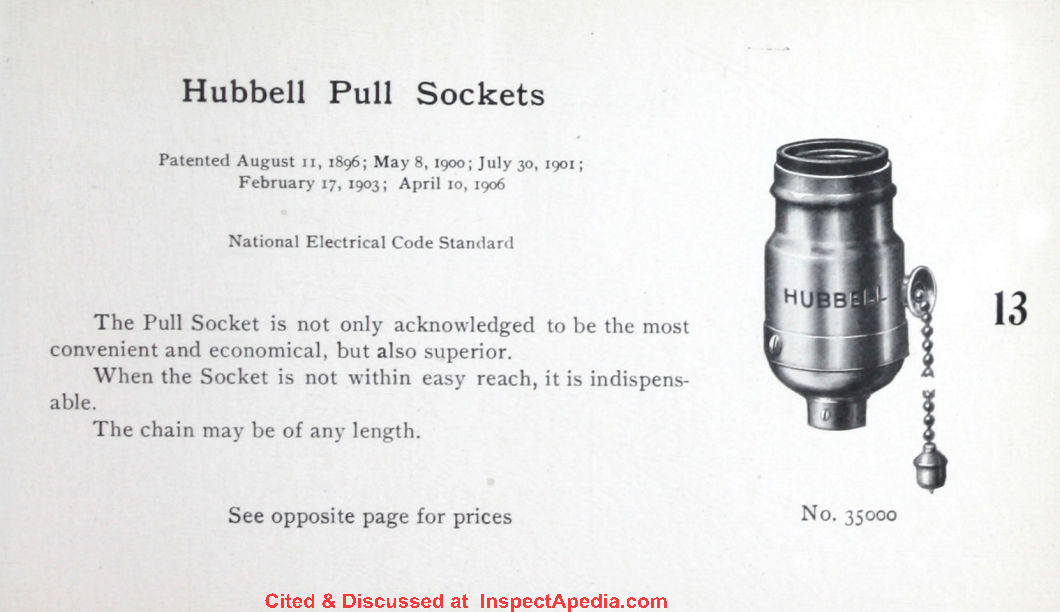
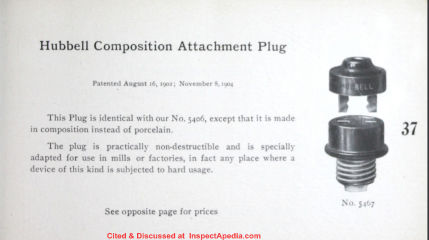
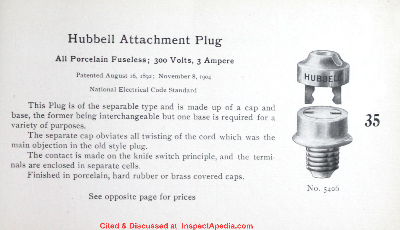
Above: Hubbell's two most-famous products included a two-bladed co-planar or "flat" attachment plug sold in both porcelain or composite versions and below his pull socket - a chain-operated light switch.
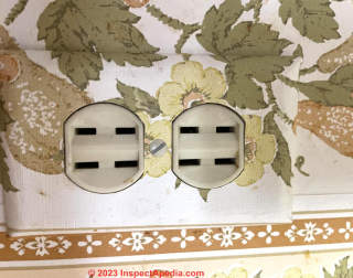
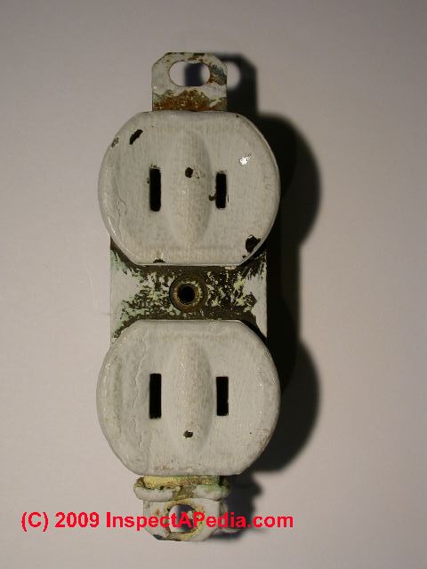
Below are photos of an ungrounded electrical receptacle found in many older homes where the electrical circuit wiring did not include a grounding conductor.
Above, a polarized, 15-Amp receptacle common up to 1960.
Below, a polarized 20-Amp receptacle, also common up to about 1960, still with no ground connector.
These receptacles can still be purchased and are the only receptacle type that should be installed on an ungrounded electrical receptacle circuit as the absence of a third ground-prong opening makes clear to the user that no ground is present.
The much painted-over receptacle shown above might date from the 1950s and was observed in a Poughkeepsie New York home built around 1910.
See FALSE GROUND at RECEPTACLES for a discussion of how this particular receptacle enjoyed giving the author a shock.
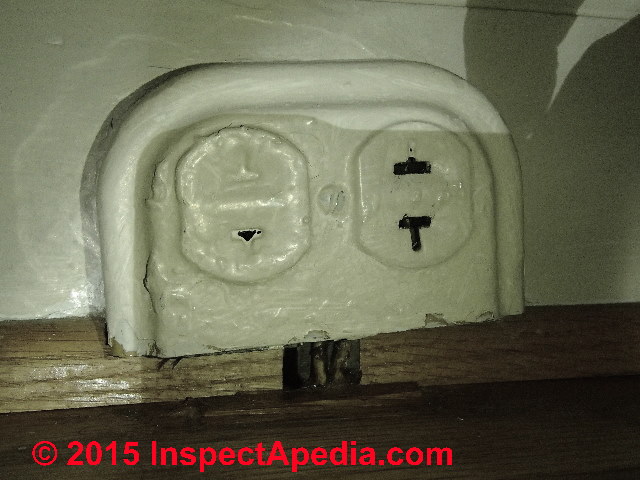
Above at right is an antique surface-mount plastic or bakelite wall receptacle or "wall plug" or "wall outlet" in common parlance. This installation is not just obsolete but improper and unsafe as you can see exposed wires poking through the wall trim below the receptacle. Property inspector Steve Smallman, Raleigh NC, who contributed this receptacle points out that
- We expect the receptacle to have been designed for a 20A circuit based on the Tee-shaped slot
- The receptacle has been heavily painted over, interfering with its use
- The wiring exposed below the receptacle is stripped-back armored cable ("BX") without proper strain relief or protection.
- If the actual circuit is powered by a 15A circuit breaker or fuse, the fact that it pretends to offer 20A is mitigated by proper fusing but could also cause trouble for the homeowner as it invites overloading.
Thanks to frequent InspectApedia contributor also cited at ABOUT InspectApedia.com
- Steve Smallman, Raleigh, NC, Email: steve@stevesmallman.com, Website: http://stevesmallman.com/ Tel: 919-669-3639 - Quoting: Steve Smallman Property Inspections (SSPI) inspectors have performed or supervised over 25,000 inspections since we introduced home inspections to the Triangle area in 1980. Mr. Smallman, located in Raleigh N.C., is a contributor to InspectApedia.com and has commented on or provided information on plumbing traps, electrical wiring, commercial FPE electrical panels and DIY Tests of FPE equipment, roofing underlayment, and building exteriors.
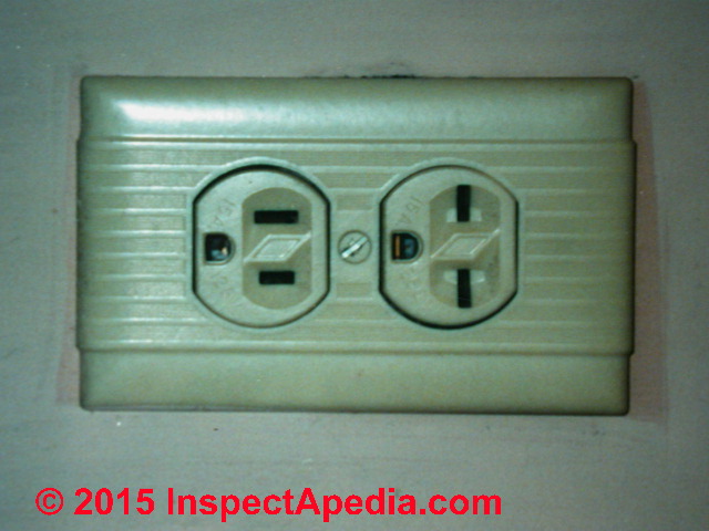
Below are two versions of another antiquated and complex electrical receptacle.
I think that these electrical receptacles provide either 120V or 240V connections depending on the receptacle and slots used and on the actual wiring present. Comments are invited.
Below: this receptacle includes a polarized, grounded 15A 120VAC receptacle at left in the photo while at right with those horizontal slots, we have a 15A 220VAC receptacle often used to power a window air conditioner in older homes.
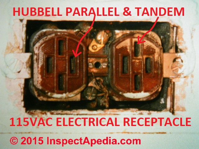
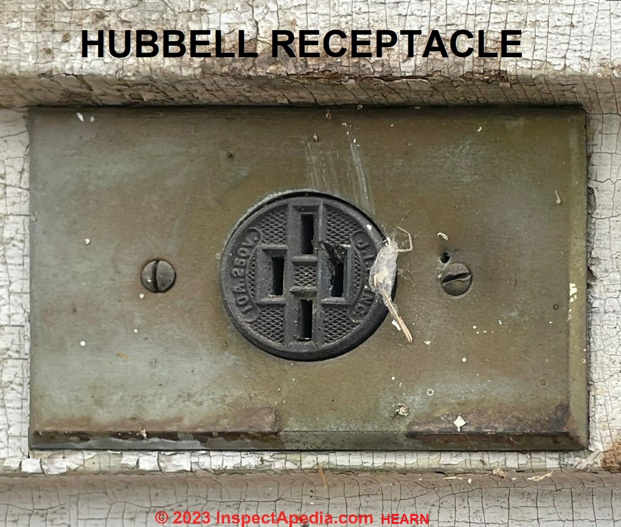
Below: an older Harvey Hubbell (1857-1927) design electrical receptacle designed to accept 120VAC wall plugs sporting either the "modern" 15A standard parallel blade design OR the older tandem design.
Hubbell, a prolific inventor of electrical receptacles, plugs, and also bulb sockets and controls, designed and patented a number of key electrical receptacles that are cited below.
The electrical receptacle shown above is also described as offering a combined parallel and tandem blade configuration patented by Hubbell - cited below. An additional and perhaps more-clear photo of this Hubbell receptacle is below in this article.
History of Antique Receptacles & Wall Plugs: the Hubbell Patents & Others
- Bossert, William F. OUTLET BOX for interior conduits [PDF] U.S. Patent 754,414, issued March 15, 1904.
- Hubbell Inc. HUBBELL CORPORATE HISTORY [PDF] Hubbell Inc., 584 Derby Milford Road Orange, CT 06477-4024 USA, Tel: (203) 799-4100
Excerpts:
1927: For the home, the Company developed a system for lighting fixture connections called "Elexit" which allowed the homeowner to install most fixtures without hiring an electrician.
Moving or replacing fixtures became much easier as did the necessary task of taking all the lighting fixtures with you when moving to a new house. - Hubbell Inc. HUBBELL ELECTRIC CO CATALOG 1906 [PDF] Western Electric Company, Eleventh & York Sts, Philadelphia PA USA, retrieved 2018/12/20, original source https://ia600607.us.archive.org/14/items/ElectricalSpecialitiesCatalogueAndPriceListNo.9August1906/Cca49543WesternElectricCo..pdf
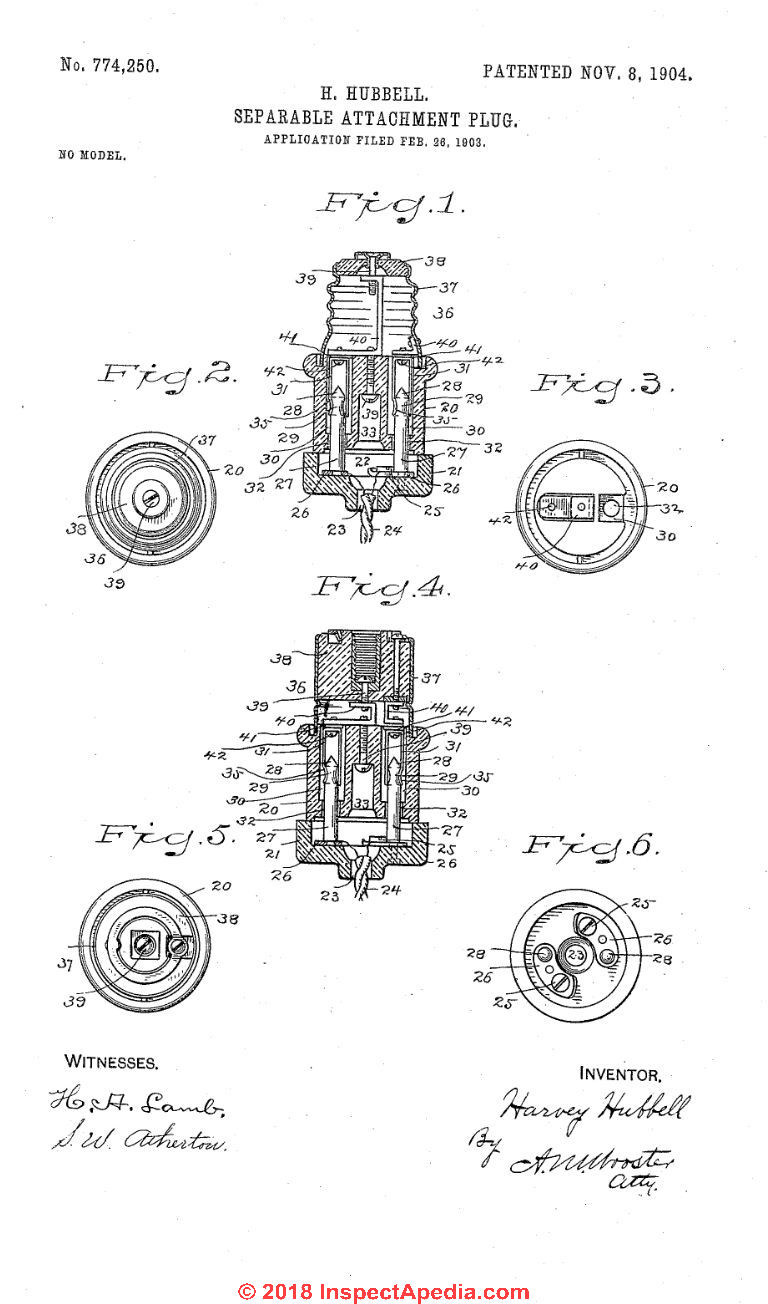
Below: illustration from Harvey Hubbell's Separable Attachment Plug patent from 1904.
[Click to enlarge any image]
- Hubbell, Harvey. SEPARABLE ATTACHMENT PLUG [PDF] U.S. Patent 774,250, issued November 8, 1904.
Excerpt:
Be it known that I, HARVEY HUBBELL, a citizen of the United States, residing at Bridgeport, county of Fairfield, State of Connecticut, have invented a new and useful Separable Attachment-Plug, of which the following is a specification.
My invention has for its object to provide a separable attachment-plug in which the cost of construction shall be reduced to the mini mum and which shall do away with the possi bility of arcing or sparking in making connection, so that electrical power in buildings may be utilized by persons having no electrical knowledge or skill in the use of tools in attaching lights, fans, motors, heating appa ratus, Surgical instruments, or any of the various appliances requiring the use of an electric current to fixtures in the circuit, the removable parts being interchangeable and one of said parts being connected to each light, group of lights, fan, or other appliance which it may be required to place in the circuit.
Photo above: a Hubbell electrical receptacle installed on a home built in 1859, courtesy of InspectApedia reader Tom Hearn. Below: illustration from Hubbell's 1904 patent showing a wall receptacle with tandem blade slots only.
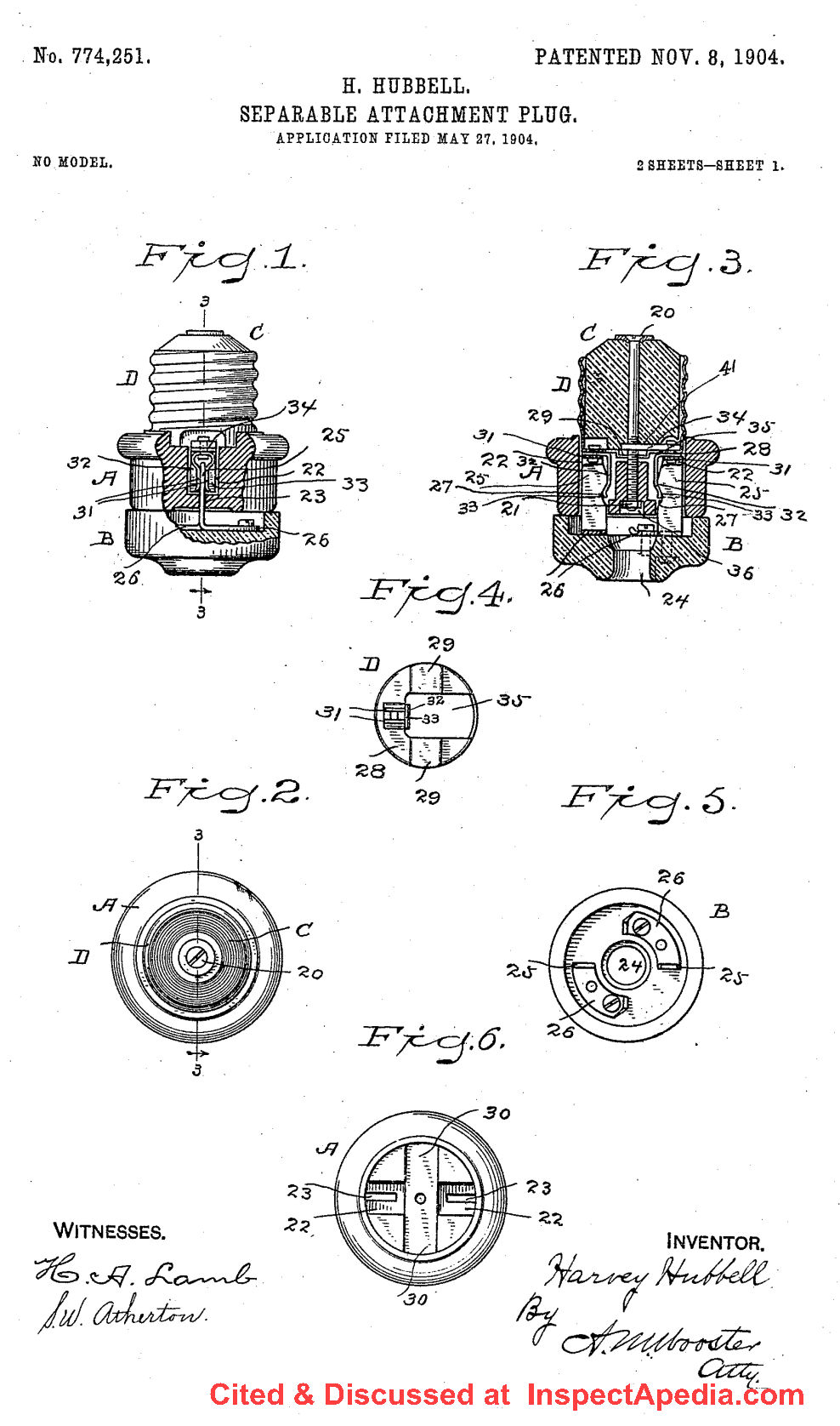
- Hubbell, Harvey. SEPARABLE ATTACHMENT PLUG [PDF] U.S. Patent 774,251, issued November 8, 1904.
Excerpt:
Be it known that I, HARVEY HUBBELL, a citizen of the United States, residing at Bridgeport, county of Fairfield, State of Connecticut, have invented a new and useful Separable Attachment-Plug, of which the following is a specification.
My invention has for its general object to produce a practical, durable, and inexpensive direct-acting separable attachment-plug that will avoid the objections raised by the underwriters to attachment-plugs of this type now upon the market and shall have for its special objects to produce a direct-acting attachment-plug in which ample current-carrying capacity shall be provided independently of locking-springs, which may or may not be used, and in which the possibility of arcing or sparking in making the contact shall be wholly done away with.
With these and other objects in view I have devised a novel attachment-plug in which a base is provided with insulating-chambers to receive contact-plates and locking-springs, if used, and with contracted insulating-passages leading to said chambers, in which the end block is made independent of the base and is secured thereto, covering the chambers, and in which an insulating-cap is provided with knife-blade contacts which engage the contact plates after they have been passed through the contracted insulating-passages.
It should be noted that the object in making the base and end block independent is to permit the formation of the insulating-chambers in the base, which receive the contact-plates and the locking-springs, if usechsaid chambers being covered by the end block, and, furthermore, that by providing contact-plates of ample current-carrying capacity in the chambers independent of the locking-springs it becomes immaterial, so far as the currentcarrying is concerned, whether or not locking-springs are used.
My present construction therefore enables me to avoid certain of the most serious objections raised by the underwriters to attachment-plugs heretofore placed upon the market.
- Hubbell, Harvey. CARTRIDGE-FUSE AND FUSE-BLOCK [PDF] U.S. Patent 819,657, issued May 1, 1906. [Illustrated above]
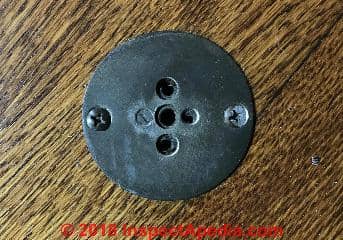
Photo above: a round pin electrical receptacle, possibly with ground and missing one mounting screw, possibly an early Hubbell-design round two-pin floor receptacle, courtesy of Bay State Home Inspections. This round-pin receptacle is not polarized, widely found in North American homes up to about 1930.
This receptacle is also similar to George Thomas' receptacle and plug design from 1910 on and cited below.
at OLD ELECTRICAL WIRING TYPES
Below: an excerpt from the patent illustration for Harvey Hubbell's multiple attachment plug patent issued in 1904.
Knife blade (flat) plug and receptacle connectors designed by Hubbell were produced as early as 1904 and became the dominant connector design used in the U.S. and Canada.
- Hubbell, Harvey. MULTIPLE ATTACHMENT PLUG [PDF] U.S. Patent 776,326, issued November 29, 1904.
Excerpt:
I Harvey Hubbell, a citizen of the United States, residing at Bridgeport, county of Fairfield, State of Connecticut, have invented a new and useful Multiple Attachment-Plug, of which the following is a specification.
My invention has for its object to provide a multiple attachment-plug which shall comprise a body adapted to engage floor, wall, or ceiling receptacles or other fixtures and a plurality of separable caps which shall be adapted to engage the body, so that a plurality of lights, groups of lights, fans, motors, heating, soldering, surgical, or other appliances may be placed in the circuit simultaneously or independently. - Hubbell, Harry C., "Portable Electrical Lamp", U.S. Patent 753,138, issued February 23, 1904
Excerpt:
I, HARRY C. HUBBELL, a citizen of the United States, residing at Brooklyn, in the county of Kings and State of New a portable electric lamp for miners use or for other purposes which will be safe, efficient, and durable. - Hubbell, Harvey. ATTACHMENT PLUG [PDF] U.S. Patent 783,275, issued February 21, 1905.
- Hubbell, Harvey. FLUSH ATTACHMENT PLUG [PDF] U.S. Patent 857,176, issued June 18, 1907. [Illustrated above]
- Hubbell, Harvey. Self-closing flush-receptacle plate [PDF] U.S. Patent 961,720, issued June 14, 1910.
- Hubbell, Harvey. PULL SOCKET [PDF] U.S. Patent 1,053,176, issued February 18, 1913. [Illustrated above]
Note: this was perhaps Hubbell's second most-significant or certainly most "famous" invention: after his flat bladed electrical wall plug and receptacle patents: the pull-chain light socket.
Excerpt:
This invention relates to pull sockets for incandescent electric lamps and has for its object to provide a construction which shall be thoroughly simplified, the number of parts and the cost of production being re duced to the minimum, and in which the operating mechanism shall be readily attachable, removable and adjustable and adapted to place the pendant close to or at any required distance from the shell, if used in connection with a globe, shade or husk, all changes and repairs being made without disturbing the works, shell or cap. - Krantz, Hubert. ELECTRICAL BOX OUTLET [PDF] U.S. Patent 740,663, issued October 6, 1903.
Excerpt:
Be it known that I, HUBERT KRANTZ, a citizen of the United States of America, residing in the borough of Brooklyn, county of Kings, State of New York, have invented Improved Electrical Outlet-Boxes, of which the following is a specification.
The main object of my invention is to provide a simple and eificient electrical outletbox the face of which can be readily adjusted toward or from the body of the box as the particular place of use may require, and this without interfering with the wires in the interior of the box.
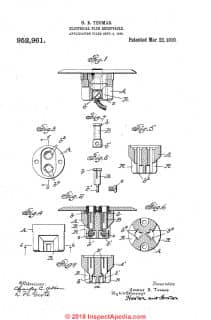
- Thomas, George B. ELECTRICAL PLUG RECEPTACLE [PDF] U.S. Patent 952,961, issued March 22, 1910. - illustrated above.
Excerpt:
Be it known that I, George B. Thomas, a citizen of the United States of America, and residing at Bridgeport, in the county of Fairfield and State of Connecticut, have invented a certain new and useful Improvement in Electrical Plug-Receptacles, of which the following is a specification.
My invention relates to plug receptacles and particularly to flush receptacles of the type described in Goodridge 7 54,863 the object of my -invention being to improve in several features the construction shown therein.
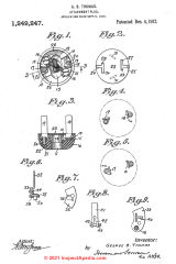
- Thomas, George B. ATTACHMENT PLUG [PDF] U.S. Patent 1,249,247, issued December 4, 1917.
Excerpt: My invention relates to attachment plugs and particularly to plugs of the jack blade type, the object of my invention being to provide a plug in which the jack blades may be shifted to various relative positions to cooperate with receptacles of different types in which the receiving contacts are variously arranged.
...
- Western Electric Co., 1906 Hubbell ELECTRICAL CATALOGUE [PDF] illustrated above, 4.8MB fast loading copy - retrieved 2023/0-7/11, original source: internet archive us.archive.org
Or load this Original copy: Large 100MB file
- Weston, E., ADAPTER or PLUG for INCANDESCENT LAMP CIRCUITS [PDF] U.S. Patent 480,900, issued Aug 16, 1892
Excerpt: Be it known that I, EDWARD WESTON, of Newark, Essex county, New Jersey, have in vented a new and useful Improvement in Adapters and Plugs for Incandescent-Lamp Circuits, of which the following is a specification.
The object of my invention is to provide a simple and convenient means whereby the terminals of electrical measuring-instruments may be connected in an incandescent or glow lamp circuit at any lamp, so that at any point on the circuit where a lamp is situated cur rent measurements may be made.
The great advantage of this plan is that it affords a sim ple and convenient way of inspecting the elec trical condition of a circuit without requiring any artificial interruption of said circuit or rendering it necessary for the inspector to go to special points to find terminals at which to connect his instrument.
The invention consists, first, in a device which I term an “adapter,’ and which is so constructed that it may be applied to the fixed portion of an incandescent-lamp socket, and hence may be substituted for the lamp after said lamp is removed. - Wikipedia, "History of AC power plugs and sockets" - retrieved 2023/07/11, original source: en.wikipedia.org/wiki/History_of_AC_power_plugs_and_sockets
...
Reader Comments, Questions & Answers About The Article Above
Below you will find questions and answers previously posted on this page at its page bottom reader comment box.
Reader Q&A - also see RECOMMENDED ARTICLES & FAQs
On 2024-01-08 by InspectApedia Publisher - 1940 home with L shaped electric receptacle
@Joseph Elliott,
Thanks for the photo and question about the "Z"or "L" shaped receptacle slots with no ground.
Above on this page at
On 2021-04-14 by Bob - old electrical outlet above sink has L-shaped or obtuse-angle shaped plug spade openings
- you'll see that very receptacle design discussed above on this page - probably as an early means of forcing polarized plug connections.
On 2024-01-07 by Joseph Elliott
Just bought a home built in 1940. This outlet was in the living room. Put a meter on it and reads 119 volts. Anyone?
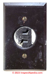
On 2023-08-12 by InspectApedia Publisher - T-slot receptacle is a non-locking plug/receptacle design,
@Rob b,
Continuing:
To be clear, I add that your NEMA 2-20 T-slot receptacle is a non-locking plug/receptacle design, NEMA 2s that is no longer in production and is considered obsolete.
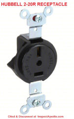
However, we illustrate below, a modern T-slot 2-20R receptacle is still produced. Below is a Hubble brand Receptacle: Single, 2-20R, 250V AC, 20 A, 2 Poles, Black, Screw Terminals, Std Protection (for sale at grainger [dot] com and other electrical suppliers) Hubbell
Part No. HBL5552B
Grainger notes that
Single receptacles like the 2-20R discussed here in antique (yours) and modern 20-Amp 250VAC versions have one outlet for making inline connections with plugs to transfer power and are often used to designate circuits for appliances and equipment.
On 2023-08-12 by InspectApedia Publisher - T slot receptacle is an electrical receptacle with just two slots, at right angles to one another
@Rob b,
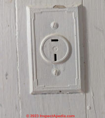
Thank you for the photo and receptacle slot pattern that I'd describe as an electrical receptacle with just two slots, at right angles to one another, also known as a "T" slot receptacle.
Your photo shows a nice example: this is a 250V (or 220V) electrical receptacle with no ground connector. I would expect to find this in an older home on an interior wall, perhaps below a window where a 220V window air conditioner was installed, or if your home is in the U.K. or other country using standard 220V instead of 120V circuits, it might be elsewhere.
In NEMA terminology this would be a 10-Amp rated 2-20R 250VAC Electrical Receptacle, perhaps installed between 1930 and 1950.
Most likely your T-slot 10A 250V receptacle is not compatible with modern T-slot plugs because on these older T-slot electrical receptacles or "outlets" the spacing of the slots is closer than the spacing of modern T-slot wall plugs.
When asking the year of an electrical component it is helpful to give some surrounding contextual information to serve as a reasonableness-check on otherwise what may have to be a rather broad guess.
Where is the building where this receptacle is found and how old is the building?
If you don't know the building's age, see
AGE of a BUILDING, HOW to DETERMINE - Visual clues indicate the age of a building
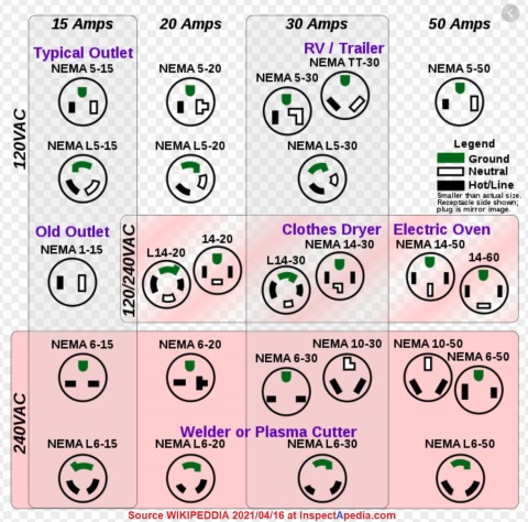
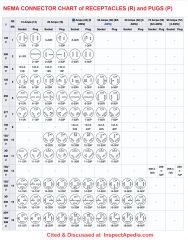
You can see this T-slot 2-50R receptacle in the NEMA connector chart that we will include below.
[Click to enlarge any image]
On 2023-08-12 by Rob b
What is this outlet for? Volts/ amps. Year?
On 2023-07-11 by InspectApedia Publisher (mod) - Example of Hubbell parallel or tandem wall plug slot receptacle
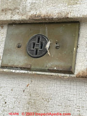
@Tom Hearn,
Thank you for the great photo and question.
The electrical receptacle in your photo is an early Harvey Hubbell receptacle that was designed to accept either of two types of wall plugs that were in use roughly from just after the turn of the last century (1904) to about 1920.
The two different wall plugs were "parallel plug connector blades" and "tandem plug connector blades".
_ _ = coplanar or flat connector blade configuration - this was the earlier design for plugs and receptacles
I I = parallel or tandem plug connector configuration - this design ultimately replaced the coplaner design for plugs and receptacles.
While parallel, flat-bladed wall plugs and receptacles, also referred to as "Fort Wayne" design plugs, were in use in the U.S. by 1996, the plug in your photo was a Hubbell design. Older wall plugs that used rounded connector pins that had been found to perform poorly.
In our citations and patents listed on this page for early wall receptacles or "plugs", you'll see that Weston's 1892 patent predates the more-famous Hubbell patents and designs.
In our OPINION Hubbell's long fight to prevent other electrical connector manufacturers from using this flat-bladed plug and receptacle design was understandable from his view but was not in the interest of safety nor of consumers. Still Hubbell's products dominated the industry and as a Wikipedia article on the history of AC power plugs and sockets reports,
By 1915, Hubbell had sold about 13 million receptacles and plug bases/caps with tandem slots/pins, and about 1.25 million with parallel slots/pins, most of which were then still in active use, meaning that Hubbell's configurations were by far the most widely used. - Wikipedia, "History of AC power plugs and sockets" cited above.
Hubbell's first wall plugs used parallel blades of equal width and length - the two center slots in your wall receptacle.
Later Hubbell wall plugs used tandem blades - the two outer slots in your wall receptacle.
Because both types of wall plugs were in use for a time, the receptacle in your photo was designed to accept either type.
Watch out: your photo shows this wall receptacle installed on what was surely an outdoor wood clapboard wall, exposed to the weather. This is not a weather-resistant wall receptacle and so is unsafe in this location, risking dangerous electrical shock.
This wall receptacle also provides no ground connector.
And by current safety standards, an outdoor receptacle is required to be protected by a GFCI or Ground Fault Circuit Interrupter - that can be provided by installing a GFCI receptacle or using a GFCI circuit breaker on this circuit, in the electrical panel.
Safest would be to turn off power to this receptacle circuit right now. If you need an outdoor electrical receptacle in this location, install a weatherproof box and GFCI receptacle. If there is no grounding conductor (no "ground wire" ) on the circuit then you'll want to add/replace the wiring so that a ground can be provided.
We'll add your Hubbell receptacle photo and keep this discussion with this article to help other readers identify this confusing (to modern folks) four-slot electrical receptacle.
We note that the bakelite receptacle face is marked as 10A 250V and shows some wear. But most-likely this is on a 120V circuit. Can you confirm that and can you post a photo of your electrical panel?
On 2023-07-10 by Tom Hearn
Old Plug found under 100 year old clapboard on our home built 1859. Please advise. Than you
[Photo above]
On 2023-05-08 by InspectApedia Editor (mod)
@Scott,
Very glad to be of help. We will look forward to seeing photos as your project goes along.
On 2023-05-08 by Scott
@InspectApedia Editor , FYI - 100 year old home in Syracuse, NY.
On 2023-05-08 by Scott
@InspectApedia Editor , This is very helpful. Thank you! Will post photos once I get going.
On 2023-03-27 by InspectApedia Editor (mod)
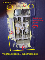 @Scott,
See my annotated version of your photo.
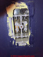
That receptacle probably has a bakelite body (some older ones even used ceramic) - mounted to /in an electrical box either by corner screws or for newer receptacles, a pair of screws centered at top and bottom of the electrical box (that I don't see in your image).
By removing just surface plaster or drywall you should find the receptacle mounting screws and also be able to find the edges of its electrical box. (I'd be surprised if there were no electrical box present but of course we don't know the location (country-city) nor age of the building where this device is present - do tell us that.
You'll want
1. turn off power to that electrical circuit and leave it off until a new receptacle is installed - it's quite dangerous as shown as anyone could touch live electrical connections
2. Hold a new plastic receptacle cover over the existing device and use a pencil to mark its outlines
3. Carefully remove drywall or plaster starting at the edges of the receptacle body, moving outwards but not past the edges of what will be covered by the new receptacle cover-plate (these come in typical and over-sized dimensions - start with a standard dimension so that you have the option of going to the larger one if necessary)
This step should uncover screws that secure the receptacle to the electrical box.
4. Take and post photos as you work - one per comment - to let me see what you're finding and I can comment further.
On 2023-03-27 by Scott
@InspectApedia Editor ,
Thank you. I am stumped as to where to start in order to remove the outlet from the wall.
Have never seen an outlet like this and not sure how it mounts. Are you aware of any pics of this type of old unit that I would give me insight into where to start to remove it?
On 2023-03-25 by InspectApedia Editor (mod) - install an ungrounded duplex electrical receptacle with GFCI in panel OR a GFCI receptacle marked "not grounded"
 @Scott,
With little trouble you can still buy these ungrounded duplex receptacles, such as the
Hubbell RR15NGWZ Duplex Receptacle Outlet, Non-Grounding, 2-Wire, 15-Amp, 120-Volt, White
shown below and costing less that $5.00 U.S.
Watch out: in a bathroom the electrical receptacle must be ground-fault protected or a GFCI device.
While your electrical inspector might be OK with adding a grounded GFCI duplex receptacle into a box where no ground is present, you may be required to mark the outlet as
NOT GROUNDED and though the GFCI might "work", it can't be tested using its normal built-in test/reset button (because that requires presence of a local ground).
Best would be to find or install a ground wire on the circuit and into the box of this bathroom electrical receptacle.
Alternatively, if you install a non-grounding receptacle like the Hubbell unit we show here, you can still provide GFCI protection for the bathroom receptacle by installing a GFCI circuit breaker in the electrical panel on the bathroom electrical circuit.
On 2023-03-25 by Scott
Attempting to identify this type of wall outlet so I can change it out. It is located in a bedroom of a 1930s home in Upstate NY.
On 2023-03-12 by InspectApedia Editor (mod)
@Amber,
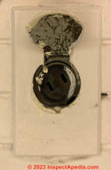
That's an ungrounded electrical receptacle, or what you're calling a wall "plug". That means that there is no electrical ground provided and you can only plug-in a "two prong plug" power cord.
The electrical receptacle may be original to the home.
Take a look at ELECTRICAL GROUNDING in OLDER HOMES. https://inspectapedia.com/electric/Old-House-Electrical-Systems.php#OldGround
On 2023-03-12 by Amber
What kind of plugs are these? I have them in my 1930’s craftsman home. They are in the utility room and my living room. They are 2 prong with flip covers on them.
On 2023-02-27 by InspectApedia Editor - 1950's GE Quad electrical receptacle without any ground provision
@Bande,
That's a 1950's GE Quad electrical receptacle without any ground provision. It allowed four two-prong, ungrounded wall plugs to be inserted rather than the more common duplex (two wall plugs) receptacle in use at that time.
Most likely that quad or four-slot electrical receptacle back-wired: that is, the hot and neutral wires were connected simply by pushing the stripped wire ends into small holes in the back of the receptacle. That type of wiring does not perform well and tends to overheat as the contact area between wire and receptacle is quite small.
That additional concern is detailed
at
BACK-WIRED ELECTRICAL DEVICES
The GE Quad receptacle in your photo is obsolete, and notably less safe than its later successors that provided a ground connection.
You'll want to ask your electrician to replace these with modern grounded receptacles, perhaps requiring some additional wiring to make a ground available.
For other readers, in addition to the Quad receptacle shown here by Bande, Monowatt Electric Corp. (a division of G.E.) made a 5-pair or quintet electrical receptacle as early as the 1930s. The Quintet Monowatt (GE) receptacle would have been so tight that multiple wall plugs with larger plug bodies would not have fit together - which may be why GE later went to the quad receptacle in your photo.
On 2023-02-23 by Bande
I have these ele outlet in many places in my home. Home built in the 60’s. I was told this was a model home for this community when built. I have never seen these before. Was there any special reason for these, that you know of?
Live in St. Charles, Missouri. St Charles county.
On 2023-01-30 by InspectApedia Publisher
@Ron Natalie,
Thank you for that added detail. If you have any photos or drawings or documents to add that'd be great, too.
DF
On 2023-01-30 by Ron Natalie
The one with the slots at an obtuse angle is not for a plug shaped like that, it's an old outlet that can accept either of the early Hubble designed plugs either the ones that look like a modern two prong OR ones that had the blades in tandem ( inline).
On 2021-04-14 by (mod) - Identify Old Electrical Receptacle with L-shaped plug blade slots
@Bob,
I haven't run into that particular receptacle but I suspect that over a kitchen sink that's probably a receptacle for a wall-hung clock. Probably 15A 120V, possibly intended to lock the plug connector of the clock.
Confirm that you have 120VAC from one slot to ground as well as from 1 slot to the other;
Also it'd help to know if the receptacle is recessed into the wall.
Perhaps you can try for a sharper photo next time.
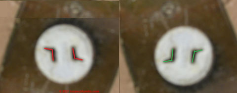
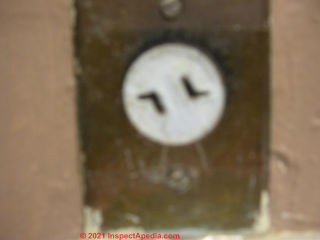
I took the liberty of copying and flipping your image upside down to show that if I've got this right, the wall plug that was inserted into this electrical receptacle would only go in one-way - that is if you flipped it over those shorter "L" arms would keep the plug from being inserted into the receptacle.
So I speculate that perhaps this was an early experiment in designing polarized receptacles, later replaced by the current design that uses one wide and one narrow blade on the wall plug whose wider blade prevents the plug from being inserted into a wall receptacle with polarity reversed.
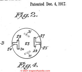
The number of electrical receptacle or "wall socket" or "wall plug" designs tried over the last 125 years is remarkable - producing more U.S. receptacle and wall plug patents alone than we can list here. Among them are some L-shaped or semi-L-shaped receptacle openings like the 1917 Thomas Patent I show below.
- Thomas, George B. ATTACHMENT PLUG [PDF] U.S. Patent 1,249,247, issued December 4, 1917.
Excerpt: My invention relates to attachment plugs and particularly to plugs of the jack blade type, the object of my invention being to provide a plug in which the jack blades may be shifted to various relative positlons to cooperate with receptacles of different types in which the receiving contacts are variously arranged.
...
Attachment plugs having their plugging jacks arranged substantially parallel or in tandem or (in a polarized plug) with their blades at right angles to each other, are well known devices on the market.
As you'll see in the sketch of current NEMA electrical receptacle types, your antique L-shaped, ungrounded, receptacle doesn't appear. I'm researching to see what else I can find.
Also take a look through the electrical receptacle patents above.
On 2021-04-14 by Bob - old electrical outlet above sink has L-shaped or obtuse-angle shaped plug spade openings
When I moved into my house 40 years ago this outlet was above the sink in the kitchen. I had no idea what it was so I never tried to use it. Can you tell me what it is? (sorry for the pictures lack of clarity)
...
Continue reading at ELECTRICAL RECEPTACLE TYPES or select a topic from the closely-related articles below, or see the complete ARTICLE INDEX.
Or see these
Recommended Articles
- AGE of a BUILDING, HOW to DETERMINE - Visual clues indicate the age of a building
- ELECTRICAL PANEL AGE
- ELECTRICAL RECEPTACLE TYPES
- FABRIC NMC WIRE INSULATION IDENTIFICATION
- OLD HOUSE ELECTRICAL SYSTEMS - home
- 2-WIRE RECEPTACLE CONNECTIONS - no ground
- ALUMINUM WIRING IDENTIFICATION
- ANTIQUE & OLD ELECTRICAL RECEPTACLES
- ASBESTOS ELECTRICAL WIRE INSULATION
- ELECTRICAL COMPONENTS, AGE, TYPES
- ELECTRICAL GROUNDING in OLDER HOMES
- ELECTRICAL OUTLET, HOW TO ADD in OLDER HOME
- GROUNDING, OLD HOUSE ELECTRICAL
- KNOB & TUBE WIRING
- NUMBER of CIRCUITS in OLD BUILDINGS
- OLD ELECTRICAL BOX TYPES
- OLD ELECTRICAL WIRING TYPES - timeline of use of different types of electrical wire & wire insulation
- POLARIZED PLUGS, RECEPTACLES, LIGHTS
Suggested citation for this web page
ANTIQUE & OLD ELECTRICAL RECEPTACLES at InspectApedia.com - online encyclopedia of building & environmental inspection, testing, diagnosis, repair, & problem prevention advice.
Or see this
INDEX to RELATED ARTICLES: ARTICLE INDEX to ELECTRICAL INSPECTION & TESTING
Or use the SEARCH BOX found below to Ask a Question or Search InspectApedia
Ask a Question or Search InspectApedia
Try the search box just below, or if you prefer, post a question or comment in the Comments box below and we will respond promptly.
Search the InspectApedia website
Note: appearance of your Comment below may be delayed: if your comment contains an image, photograph, web link, or text that looks to the software as if it might be a web link, your posting will appear after it has been approved by a moderator. Apologies for the delay.
Only one image can be added per comment but you can post as many comments, and therefore images, as you like.
You will not receive a notification when a response to your question has been posted.
Please bookmark this page to make it easy for you to check back for our response.
IF above you see "Comment Form is loading comments..." then COMMENT BOX - countable.ca / bawkbox.com IS NOT WORKING.
In any case you are welcome to send an email directly to us at InspectApedia.com at editor@inspectApedia.com
We'll reply to you directly. Please help us help you by noting, in your email, the URL of the InspectApedia page where you wanted to comment.
Citations & References
In addition to any citations in the article above, a full list is available on request.
- [1] ...
- Timothy Hemm has provided photographs of various electrical defects used at the InspectAPedia TM Website. Mr. Hemm is a professional electrical inspector in Yucala, CA.
- "Electrical System Inspection Basics," Richard C. Wolcott, ASHI 8th Annual Education Conference, Boston 1985.
- "Simplified Electrical Wiring," Sears, Roebuck and Co., 15705 (F5428) Rev. 4-77 1977 [Lots of sketches of older-type service panels.]
- "How to plan and install electric wiring for homes, farms, garages, shops," Montgomery Ward Co., 83-850.
- "Simplified Electrical Wiring," Sears, Roebuck and Co., 15705 (F5428) Rev. 4-77 1977 [Lots of sketches of older-type service panels.]
- "Home Wiring Inspection," Roswell W. Ard, Rodale's New Shelter, July/August, 1985 p. 35-40.
- "Evaluating Wiring in Older Minnesota Homes," Agricultural Extension Service, University of Minnesota, St. Paul, Minnesota 55108.
- "Basic Housing Inspection," US DHEW, S352.75 U48, p.144, out of print, but is available in most state libraries.
- In addition to citations & references found in this article, see the research citations given at the end of the related articles found at our suggested
CONTINUE READING or RECOMMENDED ARTICLES.
- Carson, Dunlop & Associates Ltd., 120 Carlton Street Suite 407, Toronto ON M5A 4K2. Tel: (416) 964-9415 1-800-268-7070 Email: info@carsondunlop.com. Alan Carson is a past president of ASHI, the American Society of Home Inspectors.
Thanks to Alan Carson and Bob Dunlop, for permission for InspectAPedia to use text excerpts from The HOME REFERENCE BOOK - the Encyclopedia of Homes and to use illustrations from The ILLUSTRATED HOME .
Carson Dunlop Associates provides extensive home inspection education and report writing material. In gratitude we provide links to tsome Carson Dunlop Associates products and services.


![Hubbell, Harvey. Cartridge-fuse and fuse-block [PDF] U.S. Patent 819,657, issued May 1, 1906. Hubbell, Harvey. Cartridge-fuse and fuse-block [PDF] U.S. Patent 819,657, issued May 1, 1906. - at InspectApedia.com](Hubbell-Patent-US819657s.jpg)
![Hubbell, Harvey. FLUSH ATTACHMENT PLUG [PDF] U.S. Patent 857,176, issued June 18, 1907. Hubbell, Harvey. FLUSH ATTACHMENT PLUG [PDF] U.S. Patent 857,176, issued June 18, 1907. at InspectApedia.com](Hubbell-Patent-US857176s.jpg)
![Hubbell, Harvey. PULL SOCKET [PDF] U.S. Patent 1,053,176, issued February 18, 1913. Hubbell, Harvey. PULL SOCKET [PDF] U.S. Patent 1,053,176, issued February 18, 1913. - at InspectApedia.com](Hubbell-Patent-US1053176s.jpg)
