
InspectAPedia® FREE Encyclopedia of Building & Environmental Construction, Diagnosis, Maintenance & Repair |
Question? Just ask us! InspectAPedia
|
 Heating Zone Valve Wiring & Manuals
Index to Zone Control Manuals & Diagrams - wire up a heating zone valve
- POST a QUESTION or COMMENT about heating zone valve wiring hookups, troubleshooting, wiring diagrams, wiring fixes
Hot water heating system zone valve installation manuals. Here is our index to zone valve manuals, sorted alphabetically by manufacturer name.
We include basic zone valve wiring instructions. For detailed zone valve wiring, choose the manufacturer from our list and then the instruction manual for your specific zone valve.
This article series describes how to wire up heating zone valves. We include wiring diagrams and installation instructions for most zone valve model and multi-zone controllers, and we describe special wiring problems that can occur if you mix different types, brands, or models of heating zone valves on the same hydronic heating (hot water heating) system.
InspectAPedia tolerates no conflicts of interest. We have no relationship with advertisers, products, or services discussed at this website.
Zone Valve Wiring Hookups for Hydronic (Hot Water) Heating Systems
 Zone Valve Manuals & Wiring Diagrams - Alphabetical
Individual Hydronic Heating Zone Valve & Control Wiring Notes by Brand are given below.
Also see
COMPATABILITY ISSUES AMONG ZONE VALVE BRANDS / MODELS - wiring conflicts & confusion
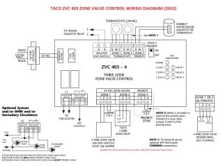
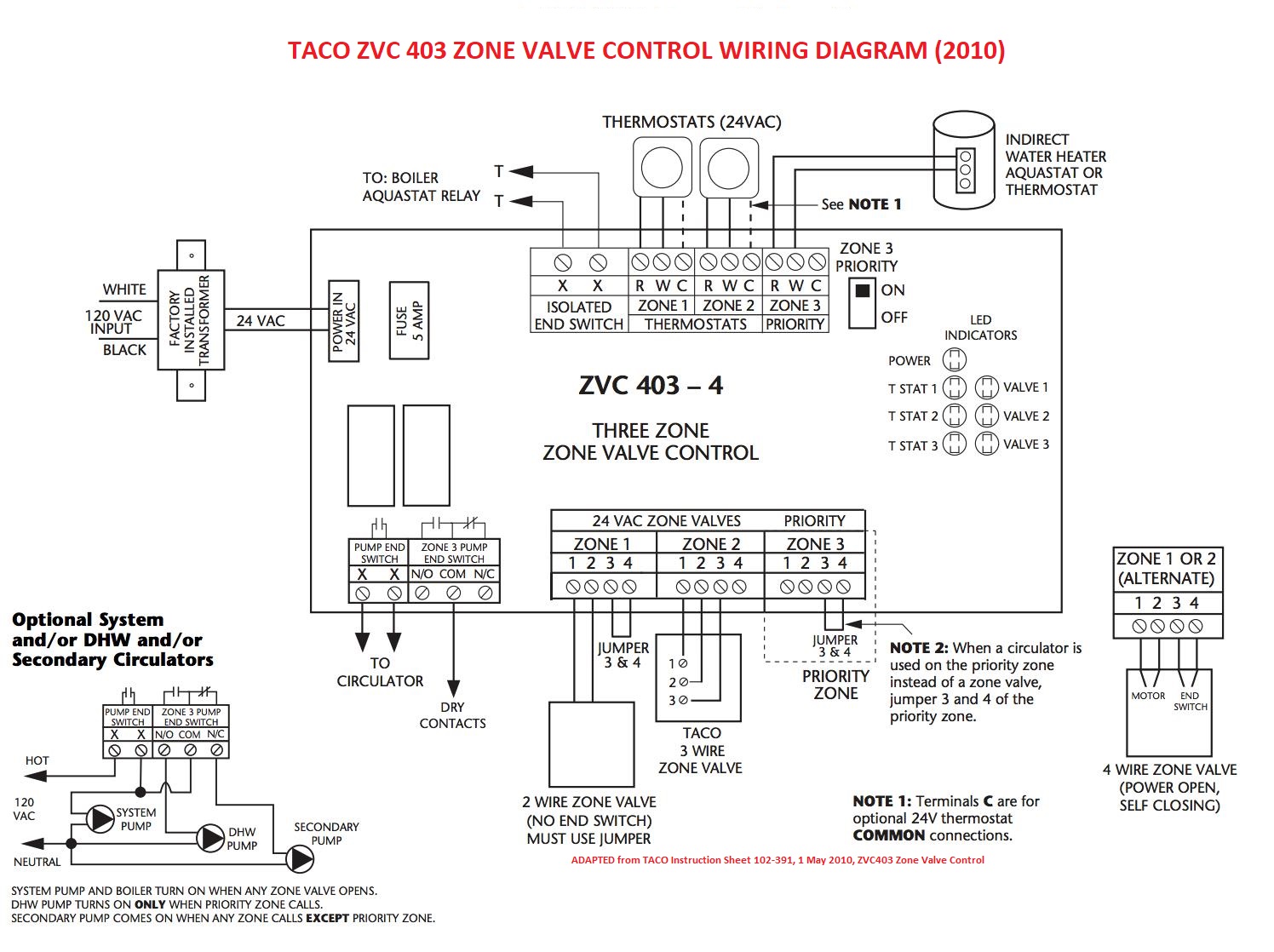
Illustration: the wiring diagram for the Taco ZVC 403 Multiple-Zone-Valve Controller. [Click to enlarge any image] - be sure to check the exact wiring diagram for your particular control and application.
- AUTOMAG ZONE VALVE WIRING - [PDF] model identification & price list
- AUTOMAG SOLID FUEL DUMP VALVE WIRING - [PDF] installation instructions
- BELIMO ZONE VALVE WIRING - [PDF] installation instructions, 33 Turner Road
Danbury, CT 06810
USA
Phone: +1 800-543-9038Fax: +1 800-228-8283E-Mail: customerservice@us.belimo.comE-Mail: technicalsupport@us.belimo.comE-Mail: orders@us.belimo.comWebsite: https://www.belimo.com/us/ Belimo, Canada Tel: 866-805-7089 Latin America/Caribbean Tel: 203-791-8396 USA Tel: 800-543-9038, Website: www.belimo.com
BELIMO ZoneTight™ ZONE VALVES TECHNICAL DOCUMENTATION [PDF] retrieved 2021/0719 original source: https://www.belimo.com/mam/americas/technical_documents/Tech%20docs/zonetight_technical_documentation.pdf
 ...
... 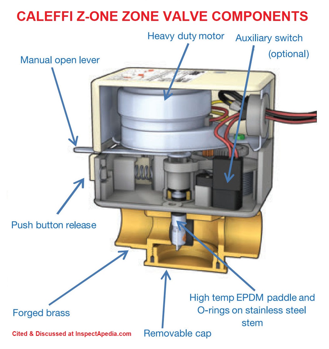
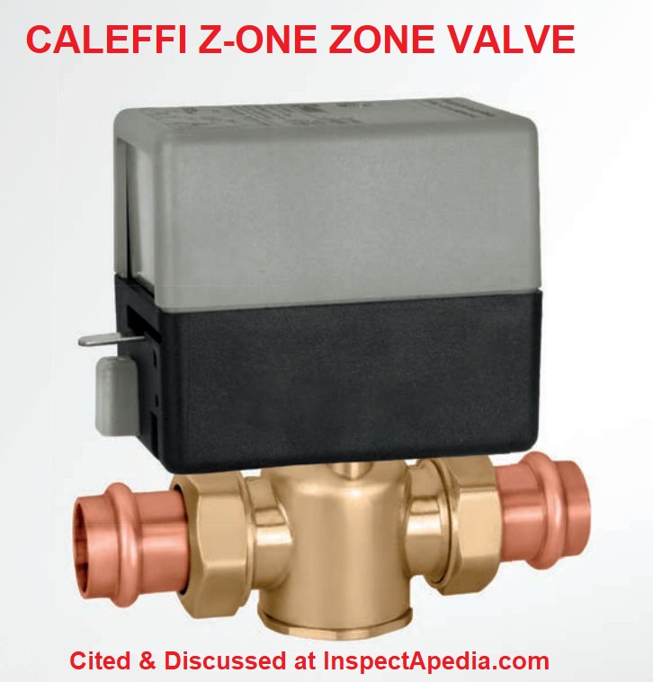
- CALEFFI ZONE VALVE INSTALLATION GUIDE [PDF] (2017) for Caleffi Z-One Zone Valves, [not available - we're still looking for this lost manual. Meanwhile see the manual listed just below - Ed.]
Caleffi North America, Inc., . 3883 W. Milwaukee Road Milwaukee, WI 53208 USA Tel. 414-238-2360 Fax 414-238-2366 Email: sales@caleffi.com Web: www.caleffi.com
Caleffi S.p.A., S.R. 229 N. 25, 28010 Fontaneto dAgogna (NO) Italy, Tel: +39-0322-8491 Email: info@caleffi.com - CALEFFI ZONE VALVE WIRING - [PDF] installation, wiring and multi-zone control set-up instructions from the manufacturer
- DANFOSS ZONE VALVES - manuals, intructions
- ERIE ZONE VALVE WIRING - [PDF] installation instructions
- FLAIR ZONE VALVE INSTRUCTIONS
- HONEYWELL ZONE VALVE INSTRUCTIONS
- HONEYWELL CONTROLS On HVAC Equipment, thermostats, primary controls, zone valves
- JOHNSON CONTROLS ZONE VALVE WIRING & INSTALLATION - [PDF] installation instructions
- MASTER ZONE CONTROL WIRING TIPS
- MACON CONTROLS ZONE VALVES
- MYSON POWER EXTRA
SPRING RETURN ZONE VALVE
MPE 222 / MPE 2 3/4 “- 2 PORT 22mm VALVE [PDF] Myson Controls, Myson Ltd., Eastern Avenue, Team Valley, Gateshead, Tyne & Wear, Ne11 OPG Sales Office No.: 0845-402-3434, retrieved 2019/12/19 original source: https://www.myson.co.uk/static_files/my/media/downloads/MPE222_Installation_sheet_Sept_2009.pdf
Excerpts from Myson: The MPE 222 is designed to control water circulation in primary hot water or central heating circuits. The motor is powered to open the valve with a spring return to the closed position. The valve is not directionally sensitive and may be fitted with flow through either Port A or Port B.
For convenience the neon indicator light illuminates, indicating when the valve is open. When the manual lever is moved to the right, the valve is open. This is used when filling, venting or draining the system. The spring return valve rests in the closed position.
... Motorised valves control the flow of water between heating and hot water zones in domestic fully pumped central heating systems. The MYSON range of Power Extra motorised valves has been designed with complete reliability and compatibility in mind.
Our motorised valves are compatible as replacements to all leading makes, so you don’t need to look anywhere else.
The range has low contact resistance switching for compatibility with the low voltage/low current switching found on many boilers throughout the UK and Europe and is compatible as a replacement to all leading makes. - SCHNEIDER ElECTRIC ZONE VALVES
- SIEMENS ZONE VALVE WIRING & INSTALLATION - [PDF] 230 page product catalog, specifications, product selection, instructions
- TACO HVAC [INDEX to all TACO Controls, manuals] TACO zone valves, zone controls, other TACO components & controls, & extensive list of installation, troubleshooting, manuals
TACO, INC., 1160 Cranston Street, Cranston, RI 02920 USA Tel: (401) 942-8000 FAX: (401) 942-2360.
TACO (Canada), Ltd., 8450 Lawson Road, Unit #3, Milton, Ontario L9T 0J8 Canada Tel: 905/564-9422. FAX: 905/564-9436.
Website: http://www.taco-hvac.com
- VALEMO ZONE VALVE IO MANUAL [PDF] (2016) Valemo Controls, Inc., Bellingham WA, Tel: 253-257-6723 website: www.valemocontrols.com Email: sales@valemocontrols.com
Valemo also sells replacement power-heads and zone valve motors for Honeywell® zone valves and for some other brands as well. See below. - VALEMO ZONE VALVE REPLACEMENT PARTS for Honeywell® zone valves [PDF] Op. CIt.
- WHITE RODGERS CONTROLS & MANUALS - all, manuals for zone valves and other White Rodgers products.
Also see THERMOSTAT WIRING WHITE RODGERS
How to Wire Multiple Taco SR502-SR506 Switching Relays
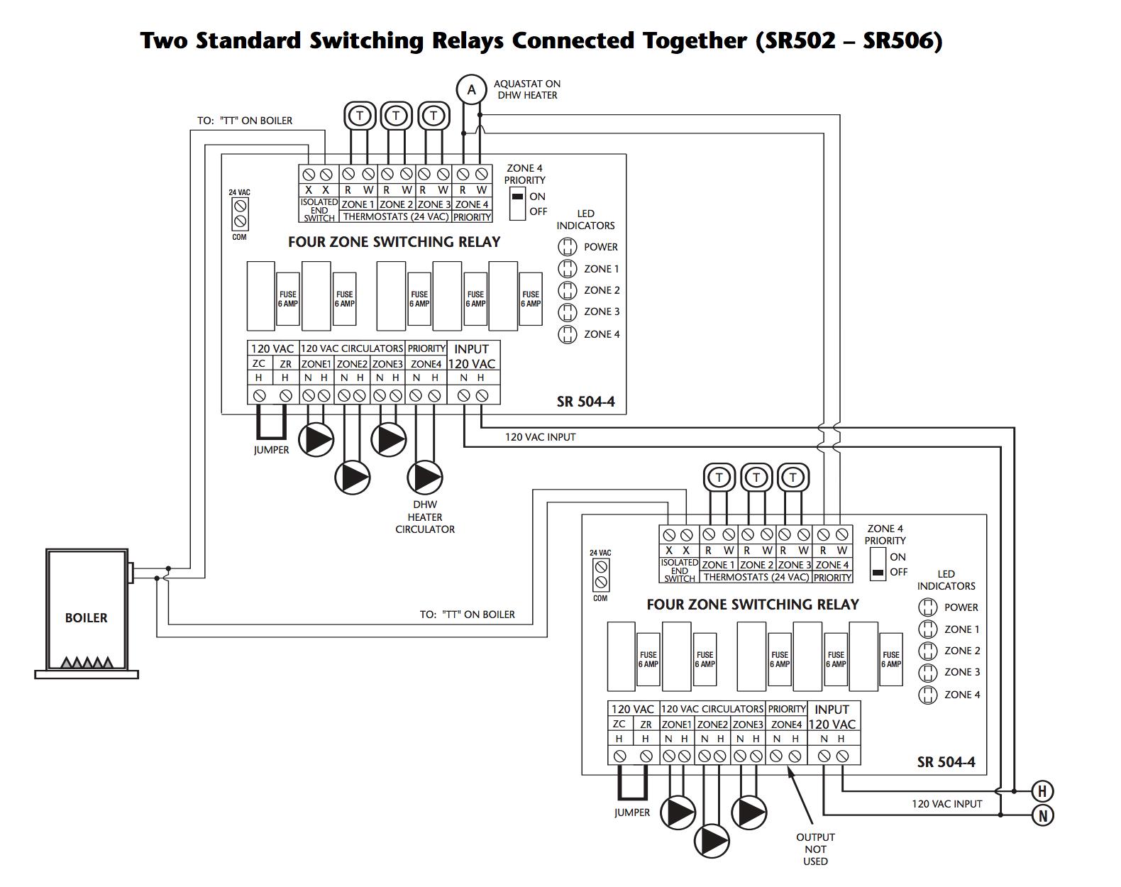
To control up to eight heating zones you might wire multiple standard switching relays together as shown in this TACO wiring diagram. This illustration is from the TACO SR503-4 Switching Relay Instruction Sheet whose link is given above. [Click to enlarge any image]
Watch out: Be sure to see important instructions and safety notes in that document.
Question: Having trouble wiring up different zone valve controller brands together
 Hi, I have a HE II Weill McClain natural gas boiler.
A few years back I converted about 1/4-1/3 or my house into hydronic radiant floor heat running off same zone as the baseboard. The guy who sweated the tubes and zoned it out has never come back to hook up the zone controller.
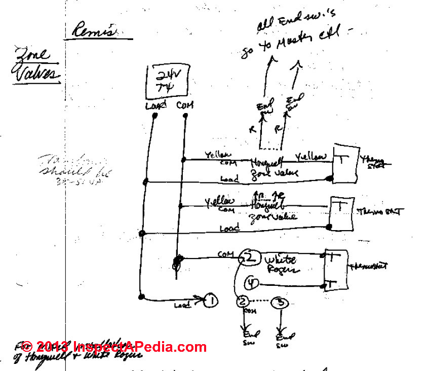
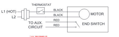
Schematic at above-left: wiring hookups for a mixed-brand zone valve installation: Honeywell & White Rogers. Click to enlarge any image or schematic.
Someone else came out the other day to hook it up. I have a TACO SR502 2-zone controller and this person purchased a Honeywell L6006C 1018 aquastat controller.
I am thinking he purchased the wrong aqua stat.
He said the whole system will never allow for 2 zones. [Click to enlarge any image]
I spoke w/techs @both TACO and WeilMcClain who, both said, I can have my floor heat operate separately from the BB units.
(I do have 2 thermostats).
Can you shed a little light on this, please? Thanks, - T.B. 10/27/2013
Reply: known problem; Example of Wiring Different Brands of Zone Control in Same System
Absolutely, if properly wired, you can take a single loop of hot water baseboard heat and subdivide it, giving each sub-loop its own thermostat and zone control valve.
Properly wired, the individual thermostat calls for heat, the zone valve opens, when the valve is fully open an end switch in the valve connects a second pair of wires that turn on the circulator pump back at the boiler.
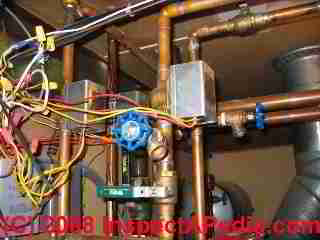
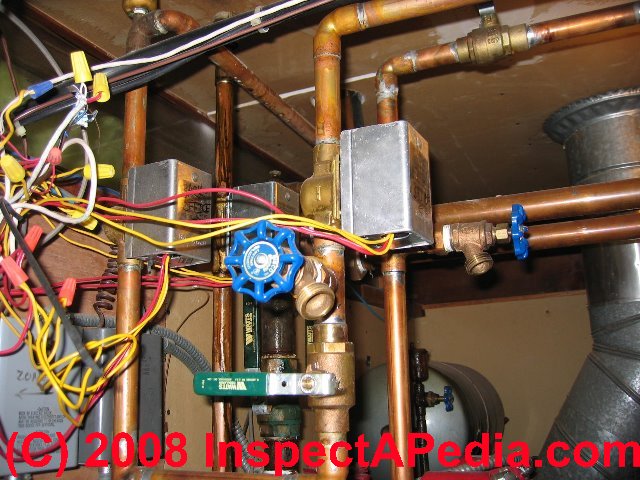
Photo below, (reader contributed) illustrates typical wiring connection at two zone valves.
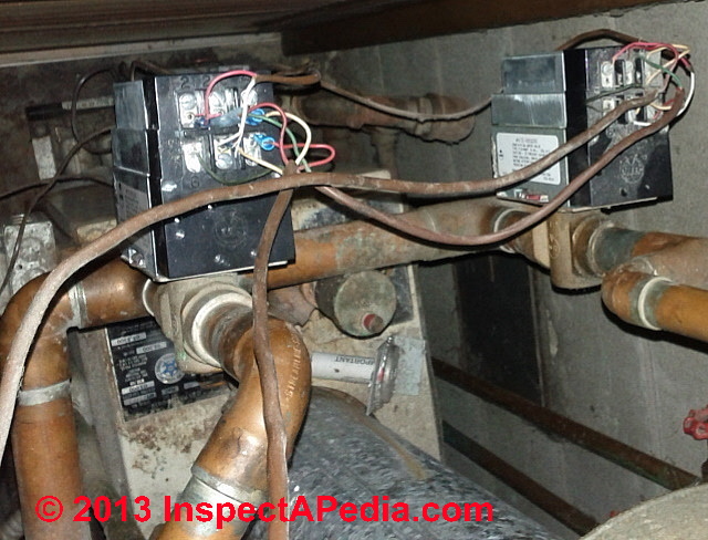 On most U.S. systems the circulator runs sending water through the open zone loops and a primary control at the boiler, monitoring water temperature, actually turns the boiler on or off as needed to re-heat the water.
In addition to your control, the Honeywell L6006C 1010, Honeywell's L8124A,C and 8151A are triple aquastats similar in function, often used to control zone valves.
Where you can run into trouble is with an installation that has a mix of different brands of zone valves. In that case, the wiring instructions for one company may be different from the other.
When I got into that trouble years ago I was wiring up a Honeywell zone valve to a system already using Flair zone valves. I called my heating supplier who had Dave Ferris (now retired) on deck to answer wiring questions.
The solution was trivial once Dave said - Just hook the red wire to terminal "x" and the yellow to "y" and so on.
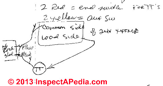
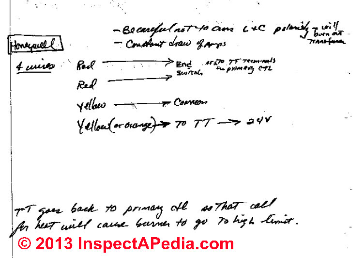
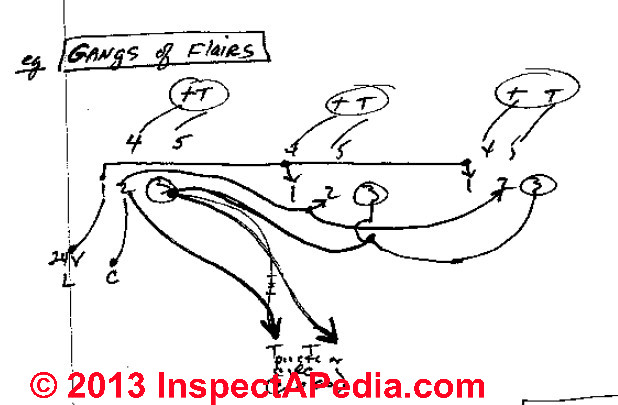
My ugly rough sketch above on this space needs to be re-drawn neatly, but there I show how we successfully wired-up a mixed brand zone valve installation. I had two Honeywell zone valves and one White Rogers zone valve. [Click to enlarge any image].
Watch out: in wiring the mixed-brand zone valves shown in my sketch above, it is important that
- The Common wire, NOT the Load side of the low-voltage transformer is taken to Terminal #2 on the White Rogers and
- The Load wire is taken to Terminal #1 on the White Rogers zone valve so that when it makes aux switch #2 there is no voltage across the switch,
and the load is taken TO the thermostats directly for the Honeywell zone valves, and - The Common is taken to the Yellow Honeywell zone valve wire.
The other yellow wire is common to the thermostat.
The correct wiring depends on the zone valve models.
Without Dave the next-best is to look with care at the instructions that came with the zone valves, and at the wiring diagrams for hook-up instructions; if you are left still confused, the manufacturer will know how to hook-up.
More about wiring Taco zone valves -
see TACO ZONE SENTRY VALVES [PDF] installation instructions
Zone Valve Compatibility Notes
 The Flair and White Rogers are compatible with one another with no special tricks
Watch out:
The Honeywell zone valves are NOT compatible with Flair and White Rogers unless you follow careful wiring details.
I give an example above, but you may need to review wiring with the manufacturers of your zone valves.
In fact Zone-A-Trol zone valve installation instructions carried this warning:
Zone-A-Trol Valves should not be wired in the same circuit with zone valves of a different make or manufacturer
without first consulting your local Zone-A-Trol representative or our factory engineering department for special wiring information. [2]
Master Control & Zone Valve & Thermostat Wiring Connection Tips
The thermostat wires on the master (primary) control will show about 20-volts from the on-board thermostat relay transformer inside the primary control.
No voltage should be presented by the zone valves, thermostat, or transformer circuit TO the primary Controller.
We see 24-volts through the zone controllers and transformer but Zero voltage on the zone valve end switch wires that go to the thermostat TT terminals on the master or primary control.
Reader Question: how many zone valves can be connected to a single thermostat?
3/5/2014 TEJ said: how many zonal valves for floor heating can be connected to one room thermostat
This question originally was posted
Reply: use of a switching relay to control multiple devices from a single thermostat
Normally one thermostat controls one heating zone and is connected to one zone valve. But as the thermostat is basically an on-off switch, indeed we've discussed with readers the successful combining of more than one zone valve switched by the same thermostat.
Watch out: to avoid overloading the TT or its power or circuit, check the zone valve wiring instructions. For switching multiple zone valves with one thermostat you may need to have the thermostat control a switching relay that in turn switches the gang of multiple zones.
A typical switching relay such as the Taco SR502 - 506 can swit3ch 4 zone valves or more.
To find out more about the Taco switching relays I cited contact
- Taco Inc., 1160 Cranston Street, Cranston, RI 02920 Telephone: (401) 942-8000 FAX: (401) 942-2360 - USA
or if you are in Canada contact
- TACO (Canada), Ltd., 8450 Lawson Road, Unit #3, Milton, Ontario L9T 0J8. Telephone: 905/564-9422. FAX: 905/564-9436.
The company's website is at www.taco-hvac.com and their wiring guide is at www.taco-hvac.com/uploads/FileLibrary/100-9.0.pdf
Danfoss Zone Valve Controls, Manuals, Instructions
- Contact: Danfoss Engineering, Website: Danfoss
Baltimore, MD
USA, Tel.: 866-375-4822, Fax: 416-352-5981
www.heating.danfoss.us https://www.danfoss.com/en/
Danfoss Canada: Toronto, ON Tel.: 866-375-4822, Fax: 416-352-5981 www.heating.danfoss.us
Danfoss has operations world wide. Various contacts are at https://www.danfoss.com/en/contact-us/
Currently Danfoss provides " ... an extensive range of products and solutions across our business segments of Danfoss Climate Solutions, Danfoss Drives and Danfoss Power Solutions"
Danfoss heating products include oil burner nozzles, oil burner fuel units, zone valves, zone valve controls, flow controllers, thermostatic radiator valves
Technical literature for Danfoss heating products: https://www.danfoss.com/en-us/service-and-support/fix-and-troubleshooting/heating-support-for-hydronic/hydronic-heating-literature/ - DANFOSS ABRA - A5 ON/OFF ZONE ACTUATOR INSTRUCTIONS [PDF] #082F1110, retrieved 2022/08/15, original source: https://assets.danfoss.com/documents/35039/AN201586406092en-010101.pdf
- Danfoss ABRA-A5 ACTUATOR for RA2000 DATA SHEET [PDF] (2016) Models 1/2" to 3/4", ABRA54200, ABRA54400, ABRA542RET2,
ABRA544RET2, for base adapters: VA33, VA50H, VA54H, VA64, VA78 (Danfoss FA 2000) - DANFOSS AVTB-RA TEMPERATURE CONTROL INSTRUCTIONS [PDF] - long wait at the company's website - gave up - Ed 2022/08/15
- DANFOSS Thermostatic Radiator Valve, Electric Zone Valve & Pressure Bypass Valve CATALOG [PDF]
Other Danfoss manuals & products are at
- OIL BURNER FUEL UNIT - Danfoss fuel units
- OIL BURNER NOZZLE GUIDE - Danfoss oil burner nozzles
Honeywell Zone Valve Wiring Wire Colors
General Honeywell Zone Valve Wiring instructions (just below) are followed by links to Honeywell Zone Valve Instruction Sheets
Typical zone valve yellow & red wire connections:
- Yellow wire connections at the zone valve: the pair of yellow wires on a zone valve are the zone valve motor actuator control.
One yellow wire connects to the C terminal on the low voltage transformer.
The second yellow wire connects to a "heat on" wire from the room thermostat.
How does this little zone valve yellow wire circuit work?
On a traditional two-wire room thermostat one wire, usually the red one, connects to the R terminal (24VAC live) on the low voltage transformer. The second thermostat wire, usually white, connects to the yellow zone valve motor actuator wire.
The second yellow zone valve wire normally connects to the C terminal (Common) on the low voltage transformer.
When the thermostat calls for heat it's acting as a low-voltage (24VAC) "on" switch that takes voltage from the low voltage transformer, through the thermostat, to the zone valve actuator motor. The second wire from the zone valve back to the low voltage transformer completes the circuit. - Red wire connections at the zone valve: the pair of red wires are "end switch" wires used to energise an external relay that turns on the circulator.
One red wire connects to the R-side of the transformer (Think "R" = "Red")
The other red wire connects to one side of the external DPDT relay that operates the circulator pump. (DPDT = "double pole, double throw" switch)
How does this little zone valve red-wire circuit work?
When the pair of yellow wires have told the (normally closed) zone valve motor to "open" that motor rotates to actually open the valve to let hot water flow.
When the zone valve has rotated to its fully-open position, inside the zone control head the two red wires are connected to turn ON the circulator pump by in turn operating a relay switch that handles the 120VAC power required to actually switch on the circulator.
[Click to enlarge any image]
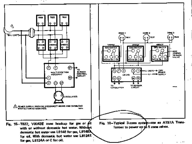
See this image for DETAILED WIRING DIAGRAMS FOR HONEYWELL ZONE VALVES V8043A, V8043E, V8043F & T822
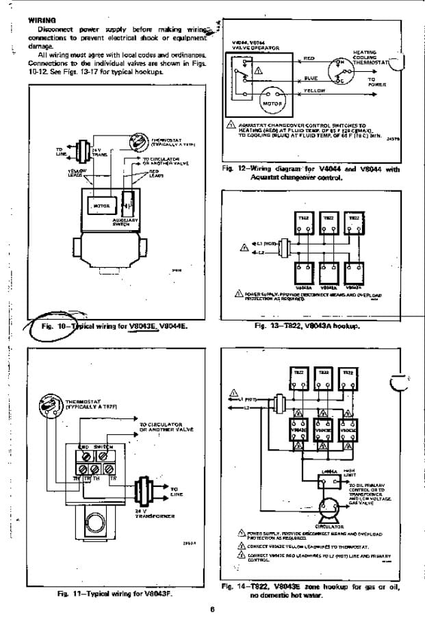
See this image for DETAILED WIRING DIAGRAMS FOR HONEYWELL ZONE VALVES V8043E & T822 & T822
See this image for DETAILED WIRING DIAGRAM FOR A TYPICAL 3-ZONE - HONEYWELL ZONE VALVES & AT87A TRANSFORMER
See this image for DETAILED WIRING DIAGRAM FOR A TYPICAL 5-ZONE - HONEYWELL ZONE VALVES & AT87A TRANSFORMER
Above Honeywell zone valve wiring diagrams are from Honeywell's motorized [zone] valve installation instructions [3]
Watch out: when installing zone valves not to overheat the valve or its parts.
 We were taught to completely remove the zone valve motor and electrical parts while sweating the zone valve to the heating system piping, but even so, overheating can damage the zone valve moving parts or o-ring seals.
Honeywell warns not to use silver solder when sweating zone valves because of the higher temperatures required with silver solder.
Honeywell Zone Valve Installation & Wiring Manuals
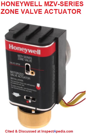
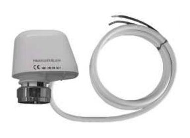
Shown here: Honeywell MZ Zone Valve Actuator motor
- HONEYWELL HPZ & HSR HYDRONIC PANEL WIRING DIAGRAMS [PDF]
- HONEYWELL HPZC105 ZONE CONTROLLER INSTALLATION MANUAL [PDF]
- HONEYWELL MZV POWER TRACK ZONE VALVE ACTUATOR INSTRUCTIONS [PDF] (2007) Honeywell International Inc. Honeywell Limited 1985 Douglas Drive North 35 Dynamic Drive
Golden Valley, MN 55422
Honeywell LimitÈe Toronto, Ontario M1V 4Z9 Website: customer.honeywell.com - HONEYWELL V8043 ZONE VALVE - [PDF] installation instructions
- HONEYWELL V4043 ZONE VALVES - [PDF] installation instructions
- HONEYWELL ZONE VALVES & VALVE PARTS CATALOG - [PDF, product catalog, 2010]
Flair Zone Valve Wiring Connections at the Thermostat & at the Zone Valve
From Flair Manufacturing's original installation instructions for the Flair Zone-A-Trol we include these wiring details. The Flair Zone-A-Trol valves in the company's wiring diagrams are typically shown wired in parallel.
How Are Multiple Zone Valves Wired?
On installations where it is not convenient to wire from valve to valve as in the diagram, a separate 3-color wire conductor can be run from terminals 1, 2, 3 of each zone valve to a convenient junction point.
By observing and respecting the color codes, conductors from corresponding-numbered terminals of each zone valve may be joined or spliced together and a single conductor may be conducted from that splice to the appropriate power and control terminals shown in the wiring diagram.
Wiring the Zone Valve:
- Black wire goes to terminal 1
- Red wire goes to terminal 2
- White wire goes to terminal 3
Wiring the Thermostat with this zone valve
- Black goes to terminal 4
- Red wire goes to terminal 5
- White wire goes to terminal 6
Watch out: when connecting wires to terminals at the zone valve and at the thermostat or any other control, do not let the stripped end of the wire touch or short out against any other wire or terminal.

Multiple zone valve wiring
Below we illustrate how a "gang" of Flair zone control valves would be wired-up.

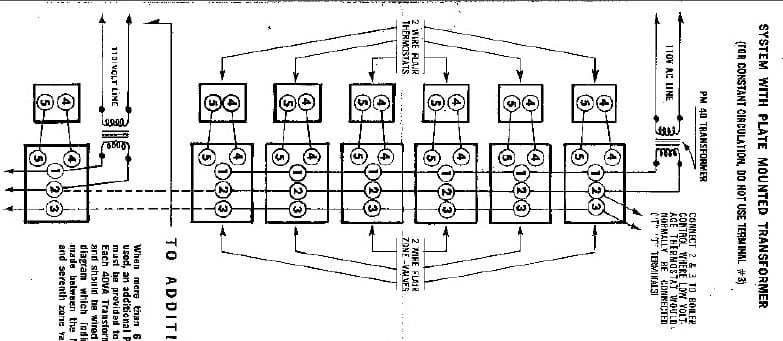
See this image for Complete and detailed wiring diagrams for FLAIR 2-WIRE ZONE-A-TROL VALVES. [image] An example from that page is shown just below.
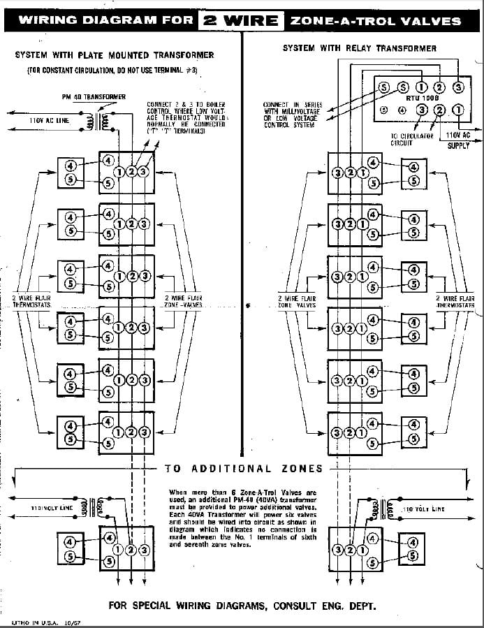
See this image for Complete and detailed wiring diagrams for FLAIR 3-WIRE ZONE-A-TROL VALVES [image]
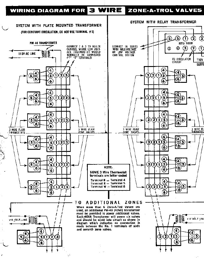
Flair Zone Valve with 2-Wire Thermostat: wiring diagram
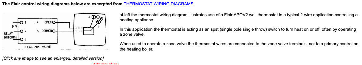
The Flair control wiring diagrams below are excerpted from THERMOSTAT WIRING DIAGRAMS
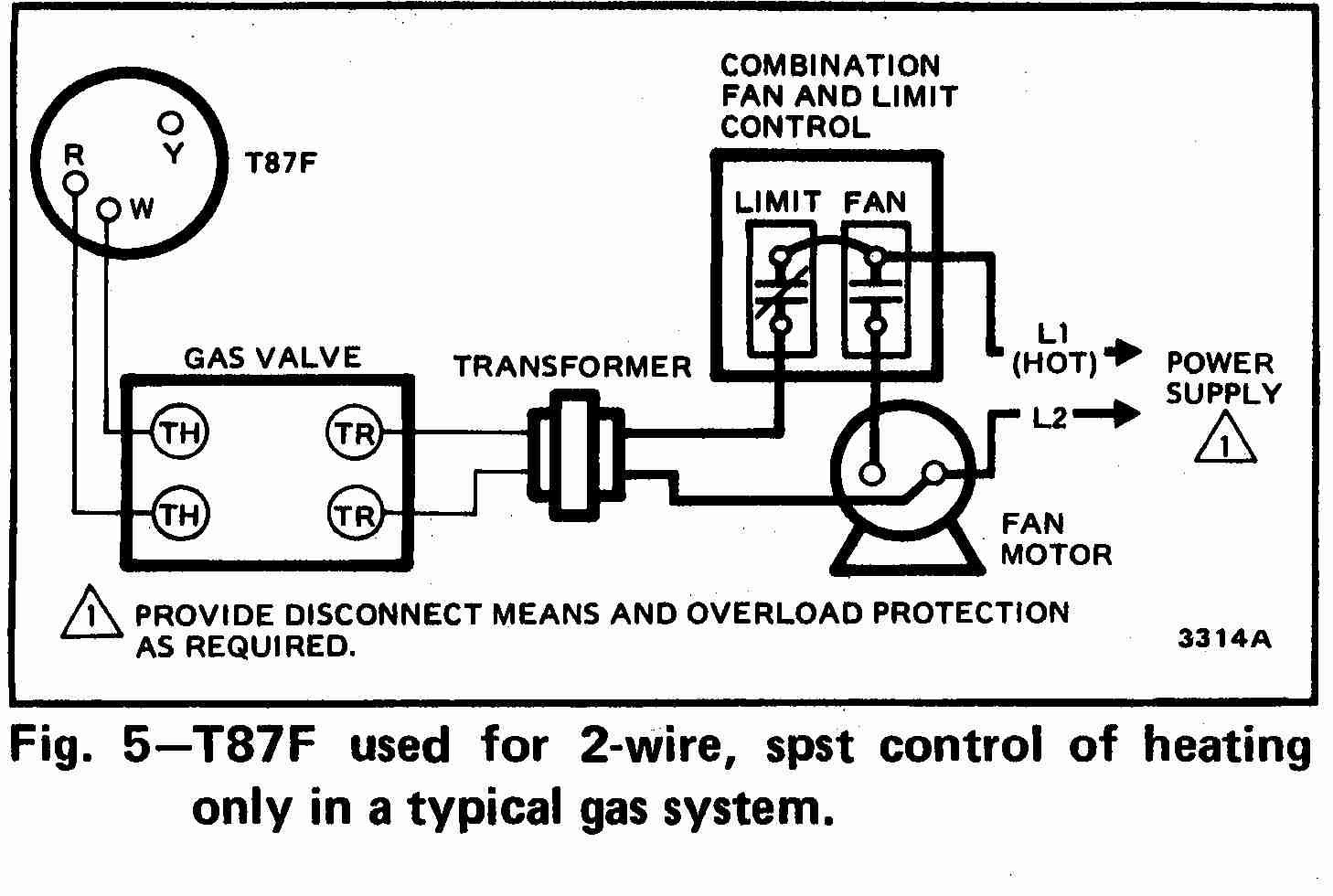 at left the thermostat wiring diagram illustrates use of a Flair APOV2 wall thermostat in a typical 2-wire application controlling a heating appliance.
In this application the thermostat is acting as an SPST (single pole single throw) switch to turn heat on or off, often by operating a zone valve.
When used to operate a zone valve the thermostat wires are connected to the zone valve terminals, not to a primary control on the heating boiler.
[Click any image to see an enlarged, detailed version]
Flair Zone Valve with 3-wire thermostat: wiring diagram
At left the thermostat wiring diagram illustrates typical use of a Flair APOV2 wall thermostat in a 3-wire application controlling a heating appliance.
In this application the thermostat is acting as a single pole double throw (SPDT) switch to control heating & cooling or in some zone valve applications.
Also see our table of Flair thermostat wiring connections found above at
- FLAIR 3-WIRE TYPE WALL THERMOSTATS - wiring instructions
The table below is an excerpt from THERMOSTAT WIRE CONNECTIONS
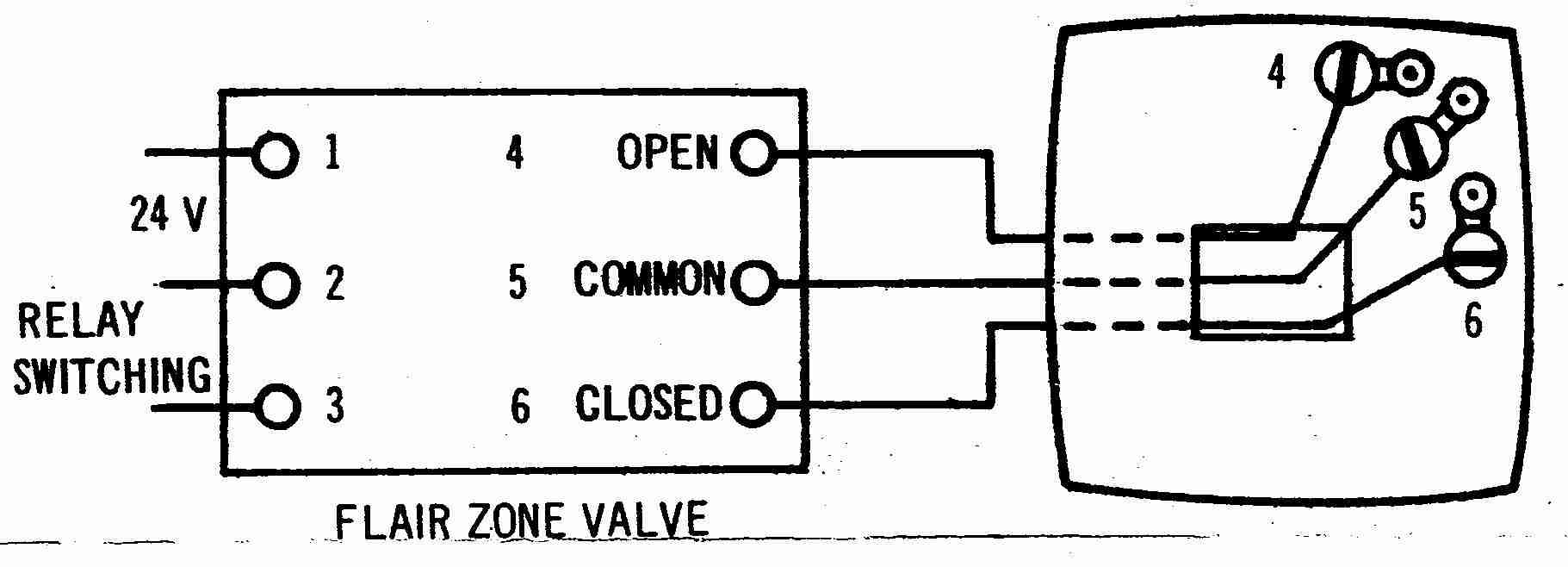
How to Wire a typical Flair 3-wire type Wall Thermostat(3 wires found in use at the wall thermostat) Flair model ANOVO Thermostat fed from a Flair zone valve |
||
| As wire colors may vary, note the wire colors | Wire coming from Flair zone valve terminal (4) "Open" . Note 1. | |
| At the Flair zone valve and | Wire coming from Flair zone valve terminal (5) "Common" | |
| Match those colors to terminals at the thermostat as shown here | Wire coming from Flair zone valve terminal (6) "Closed" | |
Notes to the Table Above
1. The [Honeywell 5-2 Day Programmable Thermostat - RTH2300B1012] thermostat cannot be used if your old thermostat had and used any two of the following wires: R, RC, RH, 4 and V.[5]
More Flair Zone Valve Wiring Instructions Diagrams
- SUPERIOR VALVES, WATERGATE I, II, AND DOUBLE ZONE [VALVES], Bulletin #801282, [PDF] Flair Manufacturing Corp, 600 Old Willets Path, Hauppage, NY 11788, Tel: 516-234-3600;
Flair Canada, Ltd., 6345 Netherhart Rd., Unit #6, Mississauga, Ontario L5T 1B8, Tel: 416-671-4664
Macon Controls Zone Valves, Manuals, Instructions
- Contact: Macon Controls, Tunstall, 118 Exchange Street · Chicopee, MA 01013 USA, Phone (413) 594-8695 · Fax (413) 598-8109 Web: www.maconcontrols.com / www.tunstall-inc.com
- Macon VMO 24 ELECTRIC ZONE VALVE OPERATOR SPECIFICATION SHEET [PDF] (2002) for use with Macon NT-Series Zone Valves
Designed for use with the Macon NT Series Valves, the VM series electric zone valve actuator is a new concept in zone controls. Utilizing a gearless electric thermic operator, this valve actuator operates off low power 24VAC.
Proportional control can be realized by using time proportioning techniques. The VM series is ideal for control of Radiators, Fin-Tube, Zones, Solar Panels, Heat Pumps etc.
- Macon ZMC-ES Series ELECTRIC ZONE VALVE ACTUATOR INSTRUCTIONS [PDF] (2014)
Excerpt:
Macon ZMC - ES Macon Model ZMC- ES 24V End switch is a thermoelectric valve drive for opening and closing valves and small valves used in the scope of HVAC technology.
The integrated micro switch with floating contact allows direct operation of a pump or fan control unit. The Macon ZMC - ES 24V End switch is controlled by a 24 V room thermostat with two-point output or pulse-width modulation.
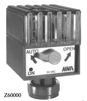
- MACON Z60000 ELECTRIC ZONE VALVE ACTUATOR INSTRUCTIONS [PDF] (2002)
Excerpt:
The Z60000 consists of an operator and a valve assembly. The operator includes a lever operated by a wax-filled heat motor and an opposing drive spring. All models include a normally closed blade switch which controls power to the motor heater when the valve is energized.
Z60000 also has normally open blade type end switch, which controls a circulator pump relay. The valve assembly consists of a brass valve body, bonnet and a springloaded valve insert.
When the valve is energized by a call for heat from the thermostat, an electric heater melts the wax inside the heat motor. The melting wax expands, driving the heat motor piston up and forcing the spring-loaded lever away from the valve stem.
When the lever starts to rise, it closes the normally open end switch to energize the circulator pump relay. The spring in the valve assembly pushes the valve stem up to follow the lever, and slowly lifts the valve disc off the valve seat.
Features:
Fits all NT Series valves.
Operator easily removed without draining system and without use of tools.
Position indicator shows whether valve is open or closed.
Provides 2-position control.
Slow-acting heat motor ensures quiet operation.
Stainless steel valve stem.
Used with 24V AC zone thermostat.
When operator is removed, spring-loaded valve automatically moves to full open position.
Z60000 has isolated end switch to operate circulator pump relay.
Schneider Electric Zone Valve Manuals
- Contact: Schneider Electric 1354 Clifford Avenue P.O. Box 2940 Loves Park, IL 61132-2940 www.schneider-electric.com/buildings
- SCHNEIDER ELECTRIC ERIE VT/VS PopTop Series ZONE VALVE INSTRUCTIONS [PDF] (2010)
On 2020-02-24 by Leo
Hi, I am having an issue with my heat that and I cannot diagnose what could be the source of the problem. I have 2 zones(2 normally closed Schneider zone valves) water boiler and 2 AHU(basement and attic).
Zone 2 heat works perfectly fine during the day, I checked the Rh and W1 wires with voltmeter, get 28V reading. When I use ecobee app standing next to the water heater and call for heat I see the zone valve opening and hot water starting to circulate. Works just as it should.
Something that I cannot explain happens at 10PM, The Rh and W1 wires reading is 0, when I call for heat the zone valve does not respond. I changed the zone valve and ecobee, did not help, exactly the same issue.
In the morning at about 9AM the power to Rh and W1 are back on and everything works fine. When during a night I use the manual ON lever on the valve the boiler kicks in and works just fine. What do you think could be issue and how could I fix it? Thank you!
On 2020-02-25 - by (mod) - troubleshooting Schneider Zone Valves
Leo
I'm puzzled too but your diagnostic steps so far are helpful; clearly something is dropping power - either just to the thermostat or to the thermostat and to the boiler itself or to a circulator or circulator relay.
The cause of power drop could be deliberate: a timer or economizer, or a poor connection or control board (perhaps affected by temperature variations).
Forcing the zone valve open and then getting heat tells me that the circulator was running but the zone valve not opening.That condition means that hot water can't circulate from the boiler through the zone and that in turn would mean the boiler is seeing the call for heat, turning on, heating up but then reaching its HI LIMIT and shutting off.
So I'd look for a sticking zone valve or bad zone valve control head.
Reader Comments, Questions & Answers About The Article Above
Below you will find questions and answers previously posted on this page at its page bottom reader comment box.
Reader Q&A - also see RECOMMENDED ARTICLES & FAQs
On 2020-10-20 - by (mod) - how do I add another 24V transformer?
Spark
You'd use an additional transformer to send 24VAC right to the zone valve that's in turn switched by the thermostat
See examples on the page above or in this example from the page:
On 2020-10-19 by Sparky
My boiler is working but isn’t the aquastat L8148A transformer to small to power four zone valves and i need to add another transformer? If so how do i wire it?
How to wire a separate transformer to my four white rogers type 1311-102 units and my Honeywell aquastat L8148A,E,J
On 2020-05-24 - by (mod) - how do I wire up my zone valves?
Eddy
Please start with the zone valve wiring described on the page above. Then don't hesitate to ask if any of that is unclear.
In the most general terms, of 4 wires at a zone valve
2 wires are connecting to the thermostat to get a call for heat - the thermostat activates the zone motor that rotates to open the valve.
2 wires connect to the circulator pump or boiler to tell it to run - that's an "end switch" that closes to turn on the circulator after the zone motor has rotated to open the zone valve.
On 2020-05-24 by Eddy
From the boiler there are 2 wires that connects to the thermostat how do i add a zone valve with 4 wires to the system?
On 2020-04-22 - by (mod) -
Sure, Steven,
Take a look at our wire size guide over at SE CABLE & BRANCH CIRCUIT WIRE SIZES vs AMPS
and you'll see three sizes of thermostat wire often used, #20, #18, and #16, but the most common is #18 wire.
In fact,
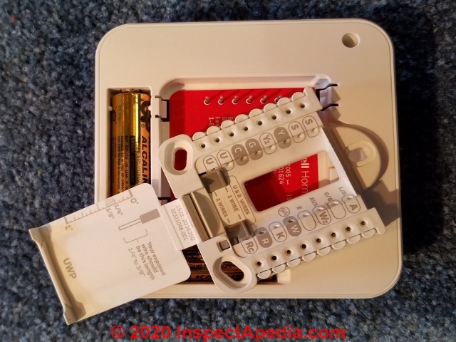 Watch out: recently, repairing a no-heat problem at a home in northern Minnesota we found that a service tech had installed a new Honeywell ProSeries programmable thermostat that was giving trouble: intermittently the thermostat just wouldn't call for heat - it would not switch on the zone circulator.
I finally tried wiggling and tugging on the thermostat wires originally wired thoughout this home in about 1960. The Honeywell thermostat uses a "push-in" thermostat wire connector and it just was not grabbing the wires reliably.
I replaced the fancy (expensive) programmable ProSeries thermostat with an older-style and very simple Honeywell T87 thermostat that uses an actual screw terminal to grab the thermostat wire.
I'm happy to report that better thermostat wire ended the recurrent no-heat problem in the home.
Taking a closer look at the old copper thermostat wire that was, after more than half a century of service, still in great shape, I noted that it was #20 wire - a bit smaller than what some modern controls anticipate, especially the push-in-connector types.
Thus I prefer #18 thermostat wire in new installations.
Below is the Honeywell ProSeries thermostat, removed from the wall, showing those push-in wiring connections.
On 2020-04-21 by steven k
hi, i'm adding a 3rd zone, heat only.
my hot water boiler is piped for it and has a vacancy,,, and my TACO box also has a 3rd zone opening.
My question is hopefully a simple one... what gauge wire do I need to run to the new thermostat??
thanks
On 2020-03-08 - by (mod) - help wiring a Valemo zone valve
Sure Bob
Take a look at the Valemo zone valve installation manual that includes wiring diagrams (like the example I give below) found at
VALEMO ZONE VALVE IO MANUAL [PDF] (2016)
On 2020-03-08 by bobblkship
Need wiring diagram for Valemo zone valve with two black wires for thermostat control and two red wires for end switch.
On 2019-11-09 - by (mod) - simple diagnosis to see why your zone won't shut off:
Tyler:
Let's do some simple diagnosis to see why your zone won't shut off:
Basically the room thermostat is nothing but an on-off switch responding to room temp.
Go to the thermostat for the heating zone that won't shut off.
Disconnect the thermostat from its wires - leave the two ends apart.
DOES THE ZONE VALVE CLOSE - or if you don't have zone valves - DOES THE ZONE CIRCULATOR STOP?
IF the zone STOPS then the problem is the thermostat itself or a setting on it
If the zone does NOT STOP
Then
It is possible that the thermostat wires are shorted together.
We'll check that next.
Simple test for shorted thermostat wires:
How to test the TT wires for a short together.
Disconnect the thermostat from the wires at the wall and leave the two TT wire ends apart - not touching
Disconnect the thermo sat wires at their other end, that will be at a zone valve OR at a circulator pump relay if you don't have zone valves; leave the two ends apart - not touching.
Then use a DMM or VOM in OHMS mode to see if there is continuity between the two wires - check both pairs of ends - if you see anything other than infinite resistance then the wires are shorted together somewhere en route.
Thermostat wires that are shorted together are functionally equivalent to the thermostat calling for heat forever.
See
inspectapedia.com/electric/DMM_VOM_Safety.php DMMs VOMs SAFE USE OF
and
inspectapedia.com/electric/DMM_How_to_Use.php DMM DIGITAL MULTIMETER HOW TO USE
OK so IF the TT wires are NOT shorted together
THEN there is either a bad zone relay controlling the circulator pump OR a bad zone valve relay that is not closing the zone valve OR a zone valve itself that is jammed "open".
On 2019-11-09 by Tyler
Having some trouble with one of my zones shutting off. Changed the thermostat and still won't stop. Any ideas to check?
On 2018-02-22 - by (mod) -
Oui Jean
R = Rouge (red)
W = Blanc (white)
B = Noir (black)
On 2018-02-22 by jean blanchette
pour être certain,l'aquastat pour bouilloire white rogers 11d05-1 les connections d'arrivée du courant sont bien dehaut en bas R pour rouge ,B pour noir etW pour blanc,MERCI, j.blanchette@hotmail.fr
Reader Question: Adding a third heating zone with its own zone valve
I am adding a third zone (basement) to my oil fired hot water baseboard heating and have it all planned as far as the plumbing is concerned.
The add-on heating zone will have it's own 24V zone valve so will require a wall mounted thermostat. I'm only looking for heat so I believe a 2 wire thermostat is sufficient. My other two zones have their own valves and thermostats and the wiring at the valves is all connected with wire nuts and doesn't make any sense to me.
I guess my question is, can I just connect my new valve and thermostat directly to the aquastat terminals that "appear" to power the other valves and thermostats ?
If so, is there anything I need to be aware of, like possibly wiring it backwards and frying something ?
If I can just add the new "loop" directly to the aquastat, in what order are the connections made ?
Example, aquastat to one connection at valve, 2nd connection at valve to one connection at thermostat, other connection at thermostat back to aquastat ?
If you need me to provide more detail on the types of thermostat, aquastat and zone valve I am using I can. My zone valve has two red wires and two yellow wires. The instructions seem to indicate that I only use the yellow wires and the red wires were for auxiliary, whatever that is. Would much appreciate your input. Thanks. - Will 11/10/11
Reply:
Will I think this will help clear things up a little for wiring a 3rd heating zone using a zone valve approach:
When the TT calls for heat (yes 2 wire is fine) it tells the zone valve for its zone to OPEN. When the zone valve is fully open it in turn tells the circulator pump to start pumping. (There is an "end switch" in the zone valve that performs this second function).
So you'll find a pair of wires from TT to the zone valve and a pair of wires from the zone valve to the circulator relay.
Watch out though: the wiring connections can vary a bit among zone valve brands - if all of yours are the same brand you can look at the existing valve, follow the wires, and you'll see how the zone valve is hooked up. If there are different brands you'll need to ask for a clue from your HVAC supplier or the manufacturer.
Reader follow-up:
Dan, thanks for the information. So I effectively have two circuits to connect. One 24v circuit runs in series as follows - transformer, zone valve, thermostat, transformer. Please can you confirm this.
The other circuit is simply connecting the other two wires on the zone valve to the connections on the circulator relay.
For the first circuit, do you know where my transformer is likely to be located ? I have the box on the front of my furnace which contains controls for how hot the water gets and when it needs to be heated. Would it be in there ?
For the second circuit to the relay, I'm assuming the relay is attached to the circulator pump itself.
...
Continue reading at ZONE VALVES, HEATING - topic home, or select a topic from the closely-related articles below, or see the complete ARTICLE INDEX.
Or see ZONE VALVE WIRING FAQs - questions & answers posted originally at this article
Or see these
Recommended Articles
- AIRBOUND HEAT SYSTEM REPAIR by WATER FEED VALVE if your heating zones don't get hot even though the zone valve opens, the circulator runs, and the boiler heats.
- BOILER CONTROLS & SWITCHES - home
- CIRCULATOR PUMPS & RELAYS
- DIAGNOSE & FIX HEATING PROBLEMS-BOILER - home
- MANUALS for HEATING & A/C SYSTEM CONTROLS - home
- MANUALS & PARTS GUIDES - HVAC - home
- RADIATOR & ZONE CONTROL MANUALS
- THERMOSTAT WIRING DIAGRAMS - for most brands and models, connect to thermostats to zone valve
- ZONE CONTROLLER TACO ZVC403
- ZONE DAMPERS
- ZONE VALVE BANGING or BACKWARDS
- ZONE VALVES, HEATING - home
- ZONE VALVE MANUALS & WIRING INDEX - home
- ZONE VALVE SIZE vs GPM
Suggested citation for this web page
ZONE VALVE MANUALS & WIRING INDEX at InspectApedia.com - online encyclopedia of building & environmental inspection, testing, diagnosis, repair, & problem prevention advice.
Or see this
INDEX to RELATED ARTICLES: ARTICLE INDEX to HEATING BOILERS
Or use the SEARCH BOX found below to Ask a Question or Search InspectApedia
Ask a Question or Search InspectApedia
Try the search box just below, or if you prefer, post a question or comment in the Comments box below and we will respond promptly.
Search the InspectApedia website
Note: appearance of your Comment below may be delayed: if your comment contains an image, photograph, web link, or text that looks to the software as if it might be a web link, your posting will appear after it has been approved by a moderator. Apologies for the delay.
Only one image can be added per comment but you can post as many comments, and therefore images, as you like.
You will not receive a notification when a response to your question has been posted.
Please bookmark this page to make it easy for you to check back for our response.
Our Comment Box is provided by Countable Web Productions countable.ca
Citations & References
In addition to any citations in the article above, a full list is available on request.
- Taco, Inc., "Taco Zone Controls and Wiring Diagrams", Taco Inc., 1160 Cranston Street, Cranston, RI 02920 Telephone: (401) 942-8000 FAX: (401) 942-2360 - USA or TACO (Canada), Ltd., 8450 Lawson Road, Unit #3, Milton, Ontario L9T 0J8. Telephone: 905/564-9422. FAX: 905/564-9436. Retrieved 3/4/2014, original source: http://www.taco-hvac.com/uploads/FileLibrary/100-9.0.pdf
- [2] "Installation Instructions, Flair Zone-A-Trol Models"
3-wire sweat type zone valves: VJ1B0, VJ1C0, VJ1D0, VJ1E0 (models represent pipe diameters 1/2" to 1 3/4"
2-wire sweat type zone valves: VJ5C0, VJ5C2, VJ5D0, VJ5B2
Flair Manufacturing, 600 Calebs Path, Hauppage, LI* NY 11787 - [3] "Motorized [Zone] Valves [Installation Instructions]", Honeywell Corporation, 1957, Honeywell, Minneapolis MN 55408, International sales offices in principal cities of the world, Manufacturing in Australia, Canada, Finland, France, Germany, Japan, Mexico, Netherlands, Spain, Taiwan, United Kingdom, USA.
- Thank-you to Mr. Scott Meenen , G&S Mechanical Services , for providing some common thermostat wiring codes also found at Mr. Meenen's web page Malware Deleted 12/9/2014 .
Mr. Meenan provides heating, heat pump, and air conditioning repair services in Maryland, Washington D.C., and northern Virginia. He can be contacted at 301-591-1646 or by Email to Malware Deleted 12/9/2014 - 10/2010. Quoting:
We service American Standard, Amana, Arco, Arco-Air, Bryant, Carrier, Coleman Evcon, Comfortmaker, Day/Night/Payne, Dunham-Bush, Fedders, Fredrich, Goodman, General Electric, Heil, Intertherm, ICP, Janitrol, Lennox (Armstrong, Johnson Air-Ease), Miller, Modine, Nordyne, Rheem/Ruud/Weatherking, Sears, Stewart Warner, Trane, Weather King, Williams, White-Westinghouse, Whirlpool, Weil Mclain, York, (Frasier Johnson/Borg Warner) and others. - [4] Azel Technologies Inc., P.O. Box 53138 10 Royal Orchard Blvd. Thornhill, Ontario, Canada L3T 7R9 Ph: 905-223-5567 Fax: 905-223-3778 Email: info@azeltec.com, Website: www.azeltec.com.
- [5] Honeywell Controls, the company wants you to use their contact form at this web page: http://www51.honeywell.com/honeywell/contact-support/contact-us.html
Honeywell Consumer Products, 39 Old Ridgebury Road Danbury, CT 06810-5110 - (203) 830-7800
World Headquarters, Honeywell International Inc., 101 Columbia Road, Morristown, NJ 07962, Phone: (973) 455-2000, Fax: (973) 455-4807 1-800-328-5111- Honeywell product model numbers & instruction Manuals: see http://yourhome.honeywell.com/home/Applications/FindYourModelNumber.aspx
- [8] "Automatic Oil Burner Controls - Thermostats", Domestic and Commercial Oil Burners, 3rd Ed., Charles H. Burkhardt, McGraw Hill, 1969 (and later editions), ASIN B0000EG4Y8
- [9] Thermostat wiring color codes & conventions, Thanks to reader " Helpful Pointers" Regarding 24V T, 10/7/2012
- [10] Domestic Central Heating Wiring Systems and Controls, 2d Ed., Raymond Ward, Newnes, ISBN-10: 0750664363, ISBN-13: 978-0750664363,
- [12] "Heating Control Handbook for the Installer and Service Man,Oil Burner, Gas Burner and Stoker Controls", Honeywell Corporation, March 1949 [copy on file as HoneywellControlsHandbookSA1399-2-1949.pdf] . Some of the controls discussed in detail here include the
- Honeywell T1 and T11A = Series 10
- Honeywell T21A (T2) = Series 20
- Honeywell T847A = Series 80
- Honeywell RA117A (RA1) = Series 10
- Honeywell LA101A = Series 10,
- Honeywell LA419A (LA4) = Series 40
- V155A = Series 10, V435A = Series 40, V575A = Series 50, V835A = Series 80
- [13] Trane TCONT800 Series Touch Screen Programmable Comfort Control Ownes Guide, American Standard, Inc., Troup Highway, Tyler TX 75711, January 2005, Telephone: Customer Service: 1-877-3381, website: www.trane.com
- In addition to citations & references found in this article, see the research citations given at the end of the related articles found at our suggested
CONTINUE READING or RECOMMENDED ARTICLES.
- Carson, Dunlop & Associates Ltd., 120 Carlton Street Suite 407, Toronto ON M5A 4K2. Tel: (416) 964-9415 1-800-268-7070 Email: info@carsondunlop.com. Alan Carson is a past president of ASHI, the American Society of Home Inspectors.
Thanks to Alan Carson and Bob Dunlop, for permission for InspectAPedia to use text excerpts from The HOME REFERENCE BOOK - the Encyclopedia of Homes and to use illustrations from The ILLUSTRATED HOME .
Carson Dunlop Associates provides extensive home inspection education and report writing material. In gratitude we provide links to tsome Carson Dunlop Associates products and services.
 | HOME | ABOUT | ASK a QUESTION | CONTACT | CONTENT USE POLICY | DESCRIPTION | POLICIES | PRIVACY | |
| © 2024 - 1985 Publisher InspectApedia.com - Daniel Friedman | |||||||||