
InspectAPedia® FREE Encyclopedia of Building & Environmental Construction, Diagnosis, Maintenance & Repair |
Question? Just ask us! InspectAPedia
|
 How Wire a Thermostat
Thermostat Wiring Connection Tables
Hook-up Procedures for
Heating, Heat Pump, or Air Conditioning Thermostats
- POST a QUESTION or COMMENT about heating, air conditioning, and heat pump thermostat installation and wiring
Room thermostat installation & wiring guide: this article series explains the basics of wiring connections at the thermostat for heating, heat pump, or air conditioning systems.
We provide Honeywell, White Rodgers & other thermostat wiring diagrams and explanation showing how to wire a room thermostat, including just what connections to make and how wires and connectors are color coded to make things easy.
Our page top sketch, courtesy of Honeywell Controls, illustrates the wiring diagram for a traditional Honeywell T87F thermostat used for 2-wire single pole single throw control of heating only in a typical gas-fired heating system.
InspectAPedia tolerates no conflicts of interest. We have no relationship with advertisers, products, or services discussed at this website.
- Daniel Friedman, Publisher/Editor/Author - See WHO ARE WE?
Guide to Room Thermostat Installation, Location, & Wiring
 Article Series Contents
- THERMOSTAT WIRE CONNECTIONS
- THERMOSTAT LOCATIONS, BEST
- THERMOSTAT LEVELING REQUIREMENTS
- THERMOSTAT REPLACEMENT TYPES
- THERMOSTAT WIRE CONNECTIONS - 2-WIRE like the T87F
- THERMOSTAT WIRE CONNECTIONS - 3-WIRE Red, White, Blue
- THERMOSTAT WIRE CONNECTIONS - 4-WIRE Red, Yellow, Green, White
- THERMOSTAT WIRE CONNECTIONS - 5-WIRE Blue/Black, Red, White, Yellow, Green
- THERMOSTAT WIRE CONNECTIONS - 6-WIRE Red, White, Blue, Yellow, Green, Orange Wires
- THERMOSTAT WIRE CONNECTIONS - 8-WIRE Black, Red, White, Yellow, Green, Orange, Brown, Blue
- THERMOSTAT WIRE SORTING to ID R W B
- THERMOSTAT WIRING CONNECTION TABLES for Major HVAC & Thermostat Brands
- THERMOSTAT WIRING GENERIC Control Points
- THERMOSTAT WIRING in PARALLEL / MULTIPLES use multiple thermostats to control one heating or cooling zone
- THERMOSTATS for RESIDENTIAL HEATING & COOLING TRAINING COURSE [PDF] White Rodgers, Division of Emerson Electrric, 9797 Reavis Rd., St Lousis MO 63123 and Markham (Torongo) Canada, training course on thermostats, includes final quiz.
- THERMOSTAT INSTRUCTIONS & MANUALS BY BRAND & MODEL - index to thermostat installation and wiring guides by brand and model of thermostat or control
Where to Locate & Mount a Room Thermostat & what spots to avoid
Locate the room thermostat at about chest height on an interior wall, in a location where the thermostat won't be affected by drafts or other unusual temperature conditions.
[Click to enlarge any image]
Good thermostat locations are
- in a living room or dining room,
- about five feet from the floor on an interior wall and
- in a position where the thermostat will be in natural air circulation (not dead air space)
- but where the thermostat will not be exposed to strong drafts from windows, doorways, or from a heating or cooling air supply register.
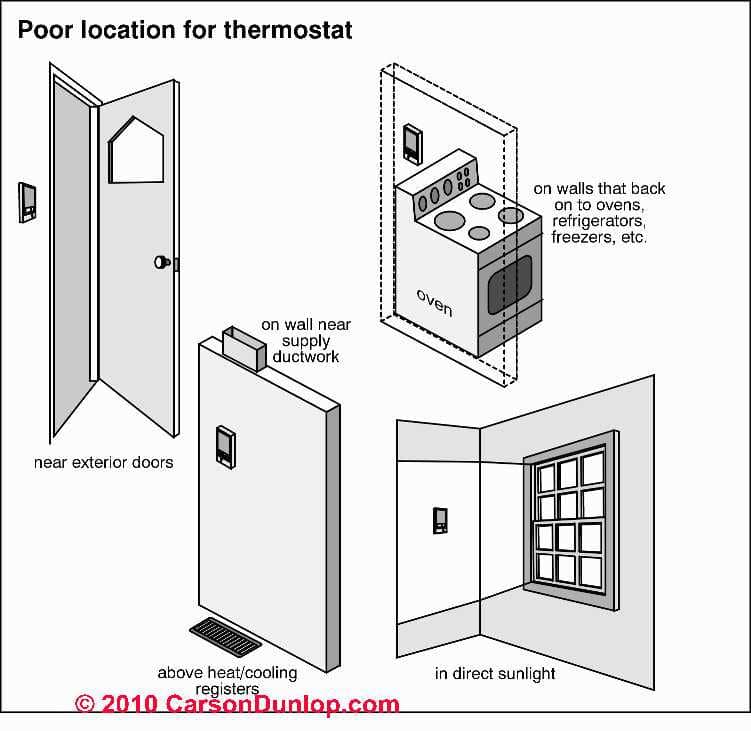
As Carson Dunlop Associates ' sketch (left) explains, there are a number of places where you should not locate the room thermostat.
Bad Room Thermostat Locations
Don't locate the room thermostat in these locations:
- on an exterior building wall (exposed to outdoor temperature effects)
- where drafts from an exterior door will affect its reading
- above or in the line of airflow from a heating or cooling air supply register
- in direct sunlight
- on a wall shared with a hot space such as a kitchen or boiler room
- in a kitchen, bath, or entry hallway
- in an alcove, behind an open door, behind furniture
- next to concealed pipes or air ducts
- Do not place heat-emitting devices such as lamps or small appliances close to the thermostat. Their heat may affect its operation.
Room Installation Thermostat Installation Tips
- Use new thermostat wires to avoid the risk of insulation nicks, cuts, and shorts in old wiring
- Seal the hole in the building wall through which the thermostat wires pass out to the thermostat mount. Drafts through wall cavities can blow out of this hole and affect proper thermostat operation.
- Do not use the thermostat power transformer to operate any other devices such as doorbells
Does the Room Thermostat Need to be Level on the Wall?
Yes for Older Mercury Bulb Switches
It's important to mount mercury-bulb thermostats as level as possible since otherwise you're putting the thermostat out of accurate temperature calibration.
That's because the coiled bimetallic spring has to move that mercury bulb to a tipped position to turn the heating or air conditioning system on or off in response to room temperature.
When we found a thermostat that did not heat a room accurately to the called-for temperature, we'd take a look to see if it was installed out of level before looking further.
Because the "set" range on these thermostats may have had a lower-end of 55 deg .F., when we wanted the thermostat to maintain a building at a temperature lower than the minimum that the thermostat dial provided, we just tilted the whole thermostat backing plate on the wall in the proper direction to shift the operating range of the switch.
No for Newer Solid State, or Digital Room Thermostats

Newer thermostats that rely on other sensor and switch designs do not have this sensitivity to being out of level and some (such as the 3M-22 thermostat) note in their installation instructions that the thermostat does not have to be level.
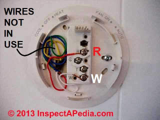
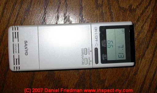
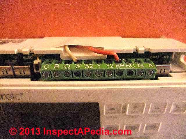
Our photo (above left) illustrates the red (R) and white (W) wire connections in a simple two wire heating control thermostat hookup using the Honeywell RTH2300/RTH221 series programmable wall thermostat.
Here is a copy of
the Honeywell RTH2300/RTH221 Series Programmable Thermostat Owners Manual [PDF]
Because some controls are used in common on hot water heat, hot air heat, and steam boilers, readers should see these other articles:
see BOILER CONTROLS & SWITCHES,
If your building uses warm air heat,
see FURNACE CONTROLS & SWITCHES.
If your building uses steam heat
Thermostat Wire Cable Types and Gauge Sizes
Thermostat wire used for heating and cooling systems is usually 18 gauge solid copper conductor, unshielded cable. Some installers may use 20 AWG copper thermostat wire.
- Use a 5-conductor thermostat cable for standard thermostat installations. Five conductor thermostat wire cables will include these colors: Blue, Green, Red, Yellow, White wires.
- Use 8 conductor thermostat wiring cable for heat pumps or multi-stage installations (staged or ganged heating or cooling). Eight conductor thermostat wire cables will include these colors: Black, Blue, Green, Orange, Red, Yellow, White wires.
Thermostat Replacement Types: What Kind of Thermostat Do I Have?
A quick scan of heating and cooling thermostats in the catalogs of HVAC suppliers such as Grainger can quickly become overwhelming as there are literally hundreds of thermostat models and quite a few different types and applications.
If you are replacing a heating or cooling room thermostat or "wall thermostat" a shortcut is to examine what is already installed.

At THERMOSTATS, HEATING / COOLING we include photographs of just about every type of heating and cooling thermostat. Here we describe further details that can help you choose a replacement thermostat that will accommodate the wires used to control you rair conditioning, heat pump, or heating system.
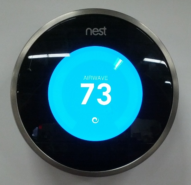
Above: A Nest Learning Thermostat. See NEST LEARNING THERMOSTATS - topic home, or
see NEST THERMOSTAT INSTALLATION & WIRING for details about wiring Nest thermostats.
Pay particular attention to the following to help sort out what you've got or what type of thermostat you need:
- Cooling, heating or both:
does the wall thermostat control only air conditioning, a heat pump, or a heating system, or both? - Type of Thermostat by Temperature sensor:
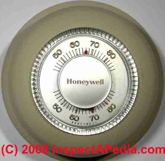
many older wall thermostats used a combination of bimetallic spring and a mercury bulb to activate the thermostat in response to room temperature. No modern room thermostat uses mercury bulbs - rather they use a thermistor or other device to respond to temperature changes.
Our photos above show a traditional round Honeywell® room thermostat and at above center my dental pick pointer indicates the mercury bulb switch in this device.
At above right is the ultra-modern Nest® thermostat - Wall mounted vs. hand held
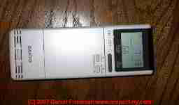
Heating or Cooling controls: while central heating and air conditioning systems are normally controlled by a wall-mounted thermostat, split systems and portable air conditioners use a control that might be wall-mounted in a bracket but can also be held in the hand. - shown below.
- Number of Control Wires Used in the Thermostat:
keep in mind that the number of wires in the wall may be greater than the number of wires actually in use. Check the colour and number of wires actually connected to your thermostat and make careful note of the terminal name, ID or number to which each wire was connected. - Type of Thermostat by Display:
analog dial versus digital display
Watrch out: In some jurisdictions there may be environmental protection restrictions on the proper disposal of mercury-containing thermostats. - THERMOSTAT WIRE CONNECTIONS - 2-WIRE like the T87F
- THERMOSTAT WIRE CONNECTIONS - 3-WIRE Red, White, Blue Wires
- THERMOSTAT WIRE CONNECTIONS - 4-WIRE Red, Yellow, Green, White
- THERMOSTAT WIRE CONNECTIONS - 5-WIRE Blue/Black, Red, White, Yellow, Green
- THERMOSTAT WIRE CONNECTIONS - 6-WIRE Red, White, Blue, Yellow, Green, Orange Wires
- THERMOSTAT WIRE CONNECTIONS - 8-WIRE Black, Red, White, Yellow, Green, Orange, Brown, Blue
- THERMOSTAT WIRE SORTING to ID R W B - separate article
- THERMOSTAT WIRING CONNECTION TABLES for all Major HVAC & Thermostat Brands
- If you do not know the brand of your thermostat, take a look
at THERMOSTAT WIRING GENERIC Control Points.
Hooking up a 2-Wire Thermostat: How Do I Install & Wire Up a Room Thermostat like the Honeywell Round Wall T87F Series Thermostat?
Basic 2-wire Room Thermostat Wiring Instructions
Wiring connections for a room thermostat such as the Honeywell 24-volt T87F, the Honeywell series 10 (out of production), or Penn "Rimset" low-voltage wall thermostat models are pretty simple as are the wiring instructions for White Rogers, Mercoid, General Controls, and similar thermostats.
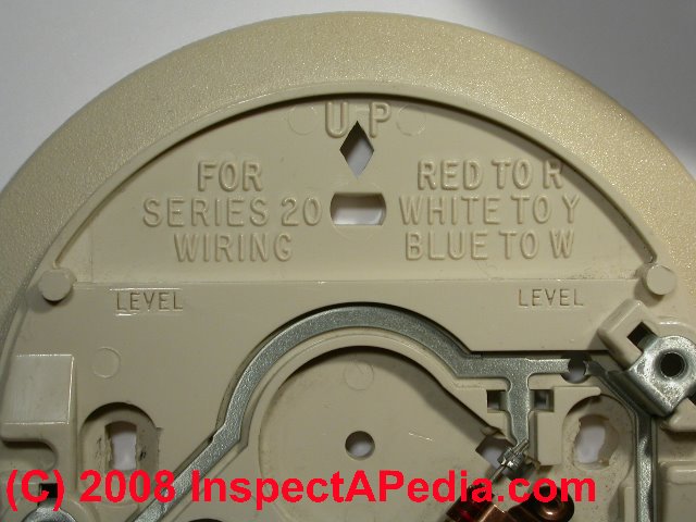
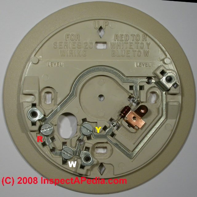
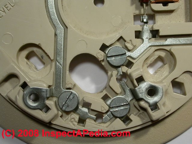
Our photo shows the backing plate that is mounted first when installing a round Honeywell Series 20 type room thermostat. Notice that the plate shows a "level" line.
We left off the actual wires so that you could see the "R" and "W" by the two screw terminals at the lower left 7 and 8 o'clock positions on the thermostat backing plate.
Note: The thermostat in this HVAC/R set-up is simply acting as an "on-off" switch to turn the heater or air conditioner on or off in response to room temperature.
The electrician or HVAC installer may have run a multi-wire set of low voltage wires through the walls of the building between the low voltage transformer and the thermostat (etc), but in this simple installation the other wires at the thermostat are not being used.
In a two-wire installation, the thermostat backing plate is mounted level on an interior wall in the room which we want to be the master temperature control for the area served by the heating or in a cooling-only climate, the cooling system.
The red wire from
the heater (or air conditioner control) or more-likely from the low voltage transformer is connected to the "R" terminal on the backing plate.
The white wire
from the heater or air conditioner control is mounted to the "W" terminal on the thermostat mounting plate. Typically the white wire is taking power from the thermostat to the operating control circuit board in the heater or air conditioner.
Typically the red wire is originating at the heating low voltage transformer and brings power to the thermostat. The transformer may be mounted on a wall near your heater, inside the heater or furnace, and on heat pump systems, on occasion the low voltage transformer may be outdoors in the compressor/condenser unit.
At the low voltage transformer you will see two wires labeled "C" for common and "R" for red. We discuss wiring the low voltage transformer itself
If you need to confirm that the low voltage transformer is working and putting out the right voltage,
see LOW VOLTAGE TRANSFORMER TEST
Summarizing, a typical 2-wire room thermostat where just three thermstat wires are all in use, the connections are as follows:
Table of 2-Wire Thermostat Connections |
||||
| Thermostat Terminal ID | Function | 2-Wire TT Wire Color |
Typical Wire Colors |
Comments |
| R | Control Power (24VAC) | Red | Red | From heater, control relay, or board originating From 24VAC from transformer to heater Common or C |
| W | Heating | White | White | To heater control relay or board |
Watch out: a few installers may not have followed the convention of Red = power.
Always use a DMM/VOM to confirm the power source. Always follow wires to the controlled device to confirm where they are connected and thus their function.
Also see COMMON HEATING AND COOLING THER MOSTAT WIRING CONNECTIONS for added details for specfic thermostat brands.
Watch Out do not short any wires together. Turn off power & confirm it is off.
Don't forget to turn off all electrical power involved with your heating system before working on thermostat wiring, and confirm that power is off where you are working by using an appropriate test instrument such as a VOM. Failure to respect this advice risks equipment damage, and in some cases electrical shock or even a building fire.
Watch out: typically an older 2-wire roomthermostat hookup is not using the C wire or COMMON wire but if you replace such a thermostat with a new WiFi or Smart room thermostat you'll need the C-wire.
See solutions at COMMON WIRE at THERMOSTATS
Where do the Thermostat Wires Start and Where do they End-Up?
As we explain in more detail
at THERMOSTAT WIRING DIAGRAMS,
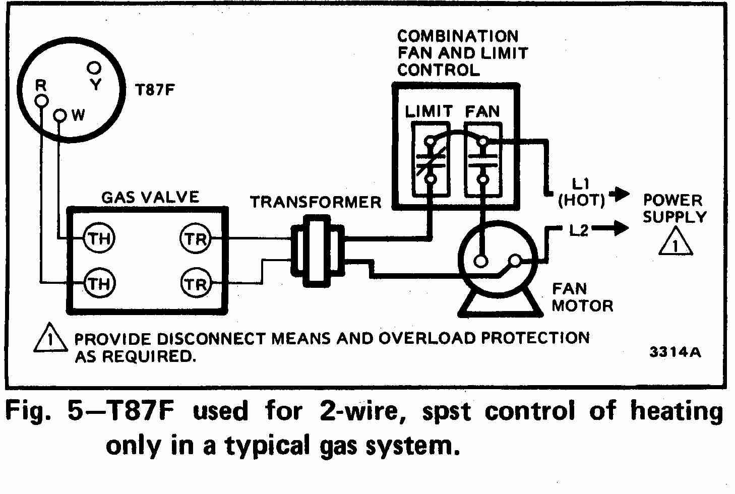
At left the thermostat wiring diagram illustrates use of a Honeywell T87F thermostat in a 2-wire application controlling a gas fired heating appliance.
In the Honeywell T87F thermostat series the single pole double throw switch makes (closes) one set of contacts when the temperature falls - to turn on the heating appliance.
In thermostats that also control a cooling system, a second set of contacts will make or close on temperature rise. This second set of contacts may also be used to operate other controls or valves in some heating systems.
[Click any image or thermostat wiring schematic to see an enlarged, detailed version]
For completeness in understanding where the red and white thermostat wires originate and end up, at below left we illustrate the red and white thermostat wires originating at the low voltage transformer, and at below right we illustrate a typical thermostat wiring connection in an R8182 Aquastat primary controller of a heating boiler, using the T and T terminals.
3-Wire Thermostats: Where Do We Connect the Red, White, & Blue (if present) Wires to a Typical Three-Wire Wall Thermostat?
Three-wire thermostat wiring instructions, also called "series 20 installations" we have three wires rather than two to connect.
Then the thermostat body is screwed in place. The screws that secure a round Honeywell traditional wall thermostat to its backing plate will also connect it properly to the wiring.
A plug connector may be used:
On other, in fact most contemporary room or wall thermostats it may be necessary to plug in a connector between the thermostat and its mounting plate.
On a typical 3-wire room thermostat where just three thermstat wires are all in use, the connections are as follows:
Table of 3-Wire Thermostat Connections |
||||
| Thermostat Terminal ID | Function | 3-Wire TT Wire Color |
Typical Wire Colors |
Comments |
| R | Control Power (24VAC) | Red | Red | Common or C wire from heater to thermostat |
| Y | Heat | White | White | |
| W | Cooling | Blue | Blue | from cooling to thermostat |
Also see COMMON HEATING AND COOLING THERMOSTAT WIRING CONNECTIONS for added details for specfic thermostat brands.
4-Wire Thermostat Wiring Connections
On a typical 3-wire room thermostat where just three thermstat wires are all in use, the connections are as follows:
Table of 4-Wire Thermostat Connections |
||||
| Thermostat Terminal ID | Function | 4-Wire TT Wire Color |
Typical Wire Colors |
Comments |
| R / RC | Control Power (24VAC) | Red | Red | Common or C or 24VAC voltage, power to heating or cooling device |
| Y | Cooling | Yellow | Yellow | Turns on A/C compressor/condenser |
| G | Fan relay | Green | Green | Furnace or air handler blower |
| W | Heating | White | White | Turns on heating furnace or heat pump contactor relay |
Notes to the Table Above
When the thermostat connects red to white you're calling for heat
When the thermostat connects red to yellow you're calling for cooling
When the thermostat connects red to green you're turning on the blower fan or air handler fan
Also see COMMON HEATING AND COOLING THERMOSTAT WIRING CONNECTIONS for added details for specfic thermostat brands.
...
5-Wire Thermostat Wiring Connections
On a typical 5-wire room thermostat where five wires are all in use, the connections are as follows:
Table of 5-Wire Thermostat Connections |
||||
| Thermostat Terminal ID | Function | 5-Wire TT Wire Color |
Typical Wire Colors |
Comments |
| C | Common C-wire | Black | Black Blue Brown | COMMON WIRE at THERMOSTATS |
| R, Rh, Rc | Control Power (24VAC) | Red | Red | |
| W, W1 | Heat | White | White | |
| Y, Y1 | Cooling | Yellow | Yellow | |
| G | Fan | Green | Green | |
Notes to the Table Above
Also see COMMON HEATING AND COOLING THERMOSTAT WIRING CONNECTIONS for added details for specfic thermostat brands.
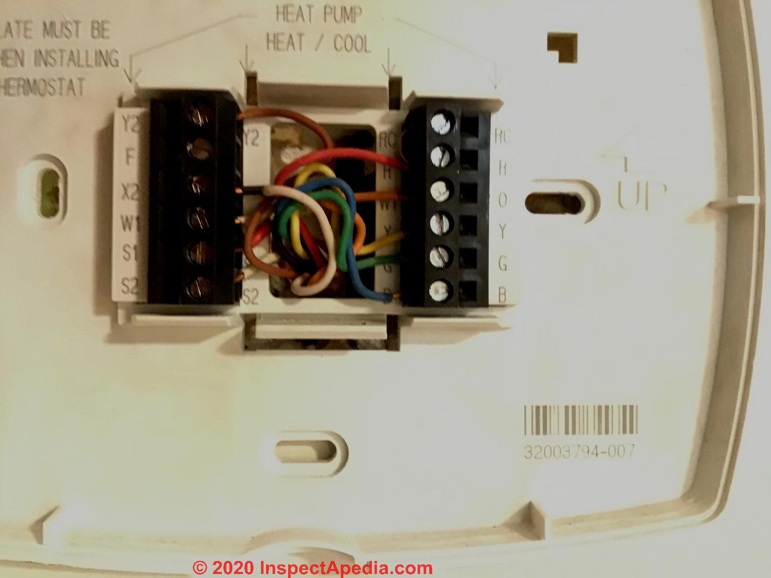
6-Wire Thermostats: Where Do We Connect the Red, White, & Blue, Yellow, Green, Orange Wires in a Typical Six-Wire Wall Thermostat?
Color Codes and Hookups for Thermostat Wires, typical for heat pump installations and thermostats
At left you can see the 11 possible thermostat wire connectors on the 3M-22 FIltrete thermostat. In this installation only two wires, R and W, have been connected.
Typical Thermostat Wire Connections for Heat Pumps
Typical connections when wiring a heat pump are given in the table below.
Again, you will have to check to see how the installer has ran the wires from the thermostat.
On a typical 6-wire room thermostat where eight wires are all in use, the connections are as follows:
Table of 6-Wire Thermostat Connections |
||||
| Thermostat Terminal ID | Function | 6-Wire TT Wire Color |
Typical Wire Colors |
Comments |
| C | Common C wire | Black | Black Blue Brown | Common connection back to transformer |
| R, Rh, Rc | Control Power (24VAC) | Red | Red | Power |
| W, W1 | Heat | White | White | Heating |
| Y, Y1 | Cooling | Yellow | Yellow | Cooling |
| G | Fan | Green | Green | Fan control |
| O / B | Reversing Valve | Orange | Orange Dark Blue |
Switch the reversing valve |
Notes to the Table Above
BLUE - the blue is usually common, dark blue (or orange) is to reversing valve
Also see COMMON HEATING AND COOLING THERMOSTAT WIRING CONNECTIONS for added details for specfic thermostat brands.
Typical thermostat connections when wiring a thermostat to control only a heating system or only an air conditioning system
If your thermostat is controlling only a heating system or only an air conditioning system, you will only have a red wire, and a white wire coming form the inside unit, to the outside unit.
On an air conditioner these two wires will go on the contactor to send 24 volts to the coil to pull the contactor in to start the air conditioner.
On a heating system these two wires will go to two thermostat connections on the primary controller such as an aquastat or air handler control that turns on the heating unit. Depending on the type of heating system, the thermostat, acting simply as an "on-off" switch will
- Hot water heat In the U.S. the TT wires will turn on a hot water circulator (or open a zone valve) on a hydronic or hot water heating system; falling boiler temperature will cause the aquastat to turn on the oil or gas burner (this is the U.S. typical installation).
- Hot water heat In Canada the TT wires will activate an aquastat control that will turn on and off the boiler based on its temperature; circulators are already running.
- Hot air heat: the TT wires will turn on the furnace heating equipment (oil or gas or electric, say); when the air temperature in the furnace heating plenum is hot enough the fan limit switch will turn on the blower fan.
These are the traditional wiring schematics, again, check the thermostat to see if this is the case with yours.
8-Wire Thermostats, Wiring Connections & Wire Colors
On a typical 8-wire room thermostat where eight wires are all in use, the connections are as follows:
Table of 8-Wire Thermostat Connections |
|||
| Thermostat Terminal ID | Function | 8-Wire TT Wire Color |
Typical Wire Colors |
| C | Common (24VAC) C-wire | Black | Black Blue Brown |
| R, Rh, Rc | Control Power (24VAC) | Red | Red |
| W, W1 | Heat | White | White |
| Y, Y1 | Cooling | Yellow | Yellow |
| G | Fan | Green | Green |
| O / B | Reversing Valve | Orange | Orange Dark Blue |
| W2 | 2nd Stage Heat | Brown | Brown |
| Y2 | 2nd Stage Cooling / Compressor | Blue | Blue |
Notes to the table above
See generic thermostat wire color code conventions in a complete set of tables
at THERMOSTAT WIRING COLOR CODES
Also see COMMON HEATING AND COOLING THERMOSTAT WIRING CONNECTIONS for added details for specfic thermostat brands.
Also see COMMON WIRE at THERMOSTATS for an explanation of this wire.
...
Instructions for Wiring of Line Voltage 120V Wall Thermostats
We moved this topic to LINE VOLTAGE 120V Wall Thermostat Wiring - separate article in order to keep our text on line voltage thermostats together.
Tables of Common Heating and Cooling Thermostat Wiring Connections for Major HVAC & Thermostat Brands
For clarity & speed we have moved wiring instructions for individual types or brand of heating or cooling thermostats to the individual articles listed below at MORE READING
Watch Out: do not short any wires together. Turn off power & confirm it is off.
As we have warned before, don't forget to turn off all electrical power involved with your heating system before working on thermostat wiring, and confirm that power is off where you are working by using an appropriate test instrument such as a VOM.
Failure to respect this advice risks equipment damage, and in some cases electrical shock or even a building fire.
We provide thermostat wiring connections for just about every type of residential heating or cooling room thermostat as well as a description of thermostat wiring color codes & conventions.
This article series answers most questions about central heating system troubleshooting, inspection, diagnosis, and repairs. We describe how to inspect, troubleshoot and repair heating and air conditioning systems to inform home owners, buyers, and home inspectors of common heating system defects.
Dayton Thermostat Installation & Wiring Guides

- Dayton, DAYTON 4PU51 THERMOSTAT MANUAL & WIRING INSTRUCTIONS [PDF] Dayton Electric Mfg. Co., Niles IL 60714, USA

- Dayton LINE VOLTAGE THERMOSTATS OPERATING INSTRUCTIONS [PDF] Models: 1UHH1 thru 1UHH4, 2NNR5 thru 2NNR9, 2NNT1 thru 2NNT5, and 6EDY3 thru 6EDY7, 2NNR7
Excerpt:
These Line Voltage Thermostats are designed for reliable use in heating, ventilating, and refrigeration applications. A broad temperature range between -30° and +120°F (-34° and +49°C) allows for a wide range of heating, ventilating, and refrigeration applications. Snap-acting contacts are in a dust protected enclosure. SPDT switches are enclosed and protected. - Dayton LINE VOLTAGE THERMOSTATS OPERATING INSTRUCTIONS incl en FRANCAIS y en ESPANOL [PDF]
- Dayton TOUCHSCREEN PROGRAMMABLE THERMOSTAT OPERATING INSTRUCTIONS & PARTS MANUAL [PDF] (2010) 6EDZ6,
- Dayton 6EDZ8 6EDZ7, 6EEA0 MANUALS - needed, use the page top or bottom CONTACT link.
Pro1 Thermostat Installation & Use Guides
- Contact: Pro1 Technologies, P.O. Box 3377, Springfield, MO 65808-3377 USA Tel: 888-776-1427 Web: www.pro1iaq.com
Email: customerservice@pro1iaq.com
Tel: 1-800-PRO1-559 or (1-800-776-1559) Toll Number (outside the US): 417-720-1435
See additional Pro1 manuals for the company's full product line found at https://pro1iaq.com/professional/technician-manuals
For each producct the company offers an installation manual and a separate operation manual
- Pro T725 THERMOSTAT INSTALLATION MANUAL [PDF] Pro1 Technologies, P.O. Box 3377, Springfield, MO 65808-3377 USA Tel: 888-776-1427 Web: www.pro1iaq.com
- Pro T725 THERMOSTAT OPERATION MANUAL [PDF] (Op. Cit.)
- Pro1 T955 WH THERMOSTAT INSTALLATION MANUAL [PDF] Op. Cit. Pro1 Manuals for the 900-series
- Pro1 T955 WH THERMOSTAT INSTALLATION MANUAL [PDF] Op. Cit. Pro1 Manuals for the 900-series
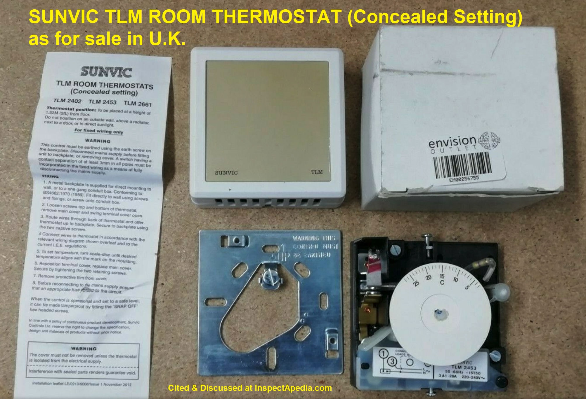
Sunvic Room Thermostat Wiring Guides
Shown below, a Sunvic room thermostat for sale in the U.K., Models TLM2402, TLM2453, TLM2661, with an installation leaflet from 2012.
- Contact: Sunvic, Electronic Room Thermostats, Sunvic Controls Limited
Units 1 and 2 Block 1
251 Low Waters Road
Cadzow Industrial Estate
Hamilton
ML3 7QU U.K., Website: sunvic.co.uk, Tel: +44 (0)1698 812 944
Sunvic provides smart controls, programmable room thermostats, timers, electronic room thermostats, wireless and rod thermostats, thermostatic radiator valves, heat packs motorised zone valves, and other devices and equipment.
Current product line description:
Electronic room thermostats give your customers much more accurate control of their central heating or cooling systems. Rather than a conventional bimetalic strip the electronic room thermostat uses a modern electronic sensor that reacts much more quickly to changes in temperature, thus making it much more accurate than their electromechanical counterparts. Many of our models incorporate TPI control technology which can give your customers up to an additional 10% saving in their fuel bills. - Sunvic, op. cit. 7/19/2021 - Wiring guides for the company's current thermostat product line, the TLX-series, are given at https://www.sunvic.co.uk/downloads/product-installation-instructions/?resourceTypeID=10419 [July 2021]
- Sunvic TLX 1001 THERMOSTAT INSTALLATION WIRING & USE MANUAL [PDF] retrieved 2021/07/19 op. cit.
- Sunvic TLX 1012 THERMOSTAT INSTALLATION WIRING & USE MANUAL [PDF] retrieved 2021/07/19 op. cit.
...
Reader Comments, Questions & Answers About The Article Above
Below you will find questions and answers previously posted on this page at its page bottom reader comment box.
Reader Q&A - also see RECOMMENDED ARTICLES & FAQs
On 2020-11-28 by Deb - Two wire non programmable thermostat do I use w or b connector?
Two wire non programmable thermostat do I use w or b connector
On 2020-11-28 - by (mod) -
Deb you'll want to be sure you know what each of your existing thermostat wires actually is - see details at
THERMOSTAT WIRE CONNECTIONS - 2-WIRE like the T87F inspectapedia.com/heat/Thermostat_Wiring_Instructions.php#2w
where you'll see that the standard wire colours are R - red and W - white.
On 2020-11-26 by Gary - Is there a WiFi thermostat that has emergency backup heat?
Is there a WiFi thermostat that has emergency backup heat? I have a gas pack and want to use the heat pump feature for my heat but if I want gas heat on colder days I can set it to that.
All I see are cold and heat, I have a Sensi now and the heat is gas. Would like to set it to heat pump. I have a trane and replaced the trane thermostat with the Sensi.
On 2020-11-26 - by (mod) -
Gary
There might be a thermostat that will switch on backup heat but not that I've found.
Instead backup heat usually works like this:
In the heating system itself, normally a heat pump (outdoor compressor/condenser capable of running in heating or cooling mode) supplies warm or cool refrigerant to the air coil in the indoor air handler (typically a forced-air heating or cooling system).
When in heating mode if the outdoor compressor/condenser cannot provide enough heat (because of low outdoor temps) then in the air handler a control board (printed circuits, sensors, relays, etc) senses that condition and switches on a backup heat source - such as electric heaters in the air handler or an external hot water heating boiler that feeds hot water to a hot water coil in the air handler.
All of that time the call for heat was originating at the same basic wall thermostat.
On 2020-09-11 by Jeff - How would I check the Black wire function?
I replaced an older Honeywell therm with a Honeywell RTH2510/RTH2410. I replaced as they were in the old therm but no work. 6 wire--Red, White, Yellow, Green, Brown, and Black. ALL wires are in the corresponding color spots, and I have the Black in the "B" spot and the Brown in the "O" spot. Do I have it wrong?
The Orange and Blue Wires were not used and there is no C on the therm wiring lug. How would I check the Black wire function?
What other lug could the black wire go to?
what other lug could the black wire go to?
Thanks, I read through that but the Orange and Blue Wires were not used and there is no C on the therm wiring lug. How would I check the Black wire function?
On 2020-09-11 - by (mod) -
Jeff
My best-organized reply is at
THERMOSTAT WIRE CONNECTIONS - 6-WIRE Red, White, Blue, Yellow, Green, Orange Wires
https://inspectapedia.com/heat/Thermostat_Wiring_Instructions.php#6w
There you'll see that the O or B spot is usually working the reversing valve - usually that's an orange or dark blue wire.
The black wire is attached to C or common and is a 24VAC power source.
Check to see what your Black is doing.Also see COMMON WIRE at THERMOSTATS
inspectapedia.com/heat/Thermostat_Wiring_Instructions.php#6w
On 2018-11-17 by Ken - Thermostat display won't stop flashing
I installed a new Thermostat because my heat and A/C stop working at the same time. My old Thermostat would not stop flashing the battery sign even after intalling new batteries.
On 2018-11-18 - by (mod) -
Ken
This may have already been obvious to you but the first thing I would try in the circumstance you describe is to confirm that the batteries are good.
...
Continue reading at THERMOSTAT WIRE FUNCTIONS or select a topic from the closely-related articles below, or see the complete ARTICLE INDEX.
Or see THERMOSTAT WIRE CONNECTION FAQs - questions & answers posted originally at this page
Or see these
Recommended Articles
- Thermostat HEAT ANTICIPATOR ADJUSTMENT
- THERMOSTAT INSTALLATION STEPS - how to replace or install a new thermostat
- THERMOSTAT WIRING COLOR CODES & methods for identifying which thermostat wire is which if yours have lost their labels or have unclear color codes.
- THERMOSTAT WIRE CONNECTIONS detailed room thermostat installation & wiring guide for each heating or cooling system type and each thermostat brand / model
- COMMON WIRE at THERMOSTATS
- CONVERT LINE to LOW VOLTAGE THERMOSTAT
- LINE VOLTAGE THERMOSTATS
- THERMOSTAT WIRING AZEL i-LINK
- THERMOSTAT WIRING 3M-22 FILTRETE
- THERMOSTAT WIRING AMERICAN STANDARD
- THERMOSTAT WIRING ARGO
- THERMOSTAT WIRING CHROMOLOX
- THERMOSTAT WIRING DAYTON
- THERMOSTAT WIRING DOMETIC
- THERMOSTAT WIRING ELECTRIC HEAT
- THERMOSTSAT WIRING EMERSON - see also THERMOSTAT WIRING WHITE RODGERS
- THERMOSTAT WIRING FLAIR INSTRUCTIONS
- THERMOSTAT WIRING GENERIC Control Points
- THERMOSTAT WIRING GOODMAN
- THERMOSTAT WIRING HONEYWELL
- THERMOSTAT WIRING LINE VOLTAGE 120-208-240VAC
- THERMOSTAT WIRING NEST
- THERMOSTAT WIRING PRO1
- THERMOSTAT WIRING SUNVIC
- THERMOSTAT WIRING TRANE HVAC
- THERMOSTAT WIRING WHITE RODGERS
- THERMOSTAT WIRING OPENING SEAL
- THERMOSTAT WIRING in PARALLEL / MULTIPLES
- THERMOSTAT WIRE TERMINAL ID CODES / FUNCTIONS - what are the R, W, and other thermostat wire terminals used for?
Suggested citation for this web page
THERMOSTAT WIRE CONNECTIONS at InspectApedia.com - online encyclopedia of building & environmental inspection, testing, diagnosis, repair, & problem prevention advice.
Or see this
INDEX to RELATED ARTICLES: ARTICLE INDEX to HVAC THERMOSTATS
Or use the SEARCH BOX found below to Ask a Question or Search InspectApedia
Ask a Question or Search InspectApedia
Try the search box just below, or if you prefer, post a question or comment in the Comments box below and we will respond promptly.
Search the InspectApedia website
Note: appearance of your Comment below may be delayed: if your comment contains an image, photograph, web link, or text that looks to the software as if it might be a web link, your posting will appear after it has been approved by a moderator. Apologies for the delay.
Only one image can be added per comment but you can post as many comments, and therefore images, as you like.
You will not receive a notification when a response to your question has been posted.
Please bookmark this page to make it easy for you to check back for our response.
IF above you see "Comment Form is loading comments..." then COMMENT BOX - countable.ca / bawkbox.com IS NOT WORKING.
In any case you are welcome to send an email directly to us at InspectApedia.com at editor@inspectApedia.com
We'll reply to you directly. Please help us help you by noting, in your email, the URL of the InspectApedia page where you wanted to comment.
Citations & References
In addition to any citations in the article above, a full list is available on request.
- Honeywell Owner's Manual, CT87N / CT87K Round Thermostat, Honeywell International, Inc., 1985 Douglas Drive North, Golden Valley MN, 55422 or in Canada: 35 Dynamic Drive, Toronto, Ontario M1V 4Z9, Canada, Website: http://yourhome.honeywell.com retrieved 2016/03/06.
- [2] Thanks to reader S.R. for discussing loss of heat due to a thermostat wiring mistake, October 2010
- [3] Thank to Mr. Scott Meenen , G&S Mechanical Services , for providing some common thermostat wiring codes also found at Mr. Meenen's web page Malware Deleted 12/9/2014 . Mr. Meenan provides heating, heat pump, and air conditioning repair services in Maryland, Washington D.C., and northern Virginia. He can be contacted at 301-591-1646 or by Email to Malware Deleted 12/9/2014 - 10/2010. Quoting:
We service American Standard, Amana, Arco, Arco-Air, Bryant, Carrier, Coleman Evcon, Comfortmaker, Day/Night/Payne, Dunham-Bush, Fedders, Fredrich, Goodman, General Electric, Heil, Intertherm, ICP, Janitrol, Lennox (Armstrong, Johnson Air-Ease), Miller, Modine, Nordyne, Rheem/Ruud/Weatherking, Sears, Stewart Warner, Trane, Weather King, Williams, White-Westinghouse, Whirlpool, Weil Mclain, York, (Frasier Johnson/Borg Warner) and others. - [4] Azel Technologies Inc., P.O. Box 53138 10 Royal Orchard Blvd. Thornhill, Ontario, Canada L3T 7R9 Ph: 905-223-5567 Fax: 905-223-3778 Email: info@azeltec.com, Website: www.azeltec.com.
- [5] Honeywell Controls, the company wants you to use their contact form at this web page: http://www51.honeywell.com/honeywell/contact-support/contact-us.html
Honeywell Consumer Products, 39 Old Ridgebury Road Danbury, CT 06810-5110 - (203) 830-7800
World Headquarters, Honeywell International Inc., 101 Columbia Road, Morristown, NJ 07962, Phone: (973) 455-2000, Fax: (973) 455-4807 1-800-328-5111- Honeywell product model numbers & instruction Manuals: see http://yourhome.honeywell.com/home/Applications/FindYourModelNumber.aspx
- [6] White Rodgers Thermostats and HVAC controls,
Homeowner information: http://www.emersonclimate.com/en-US/brands/white_rodgers/Pages/wr-homeowner-info.aspx
Contractor information: http://www.emersonclimate.com/en-US/brands/white_rodgers/wr_contractor_info/Pages/white-rodgers-contractor-info.aspx
White Rodgers Product Catalog (don't misspell the company's name as White Rogers Thermostats) -
http://www.emersonclimate.com/Documents/thermostats.pdf - Thermostat Catalog - [7] White Rodgers 1F90 Low Voltage Digital Comfort-Set thermostat Installation Instructions, PN 37-3654, White-Rodgers Division, Emerson Electric Co., 9797 Reavis Rd., St. Louis MO 63123
- [8] "Automatic Oil Burner Controls - Thermostats", Domestic and Commercial Oil Burners, 3rd Ed., Charles H. Burkhardt, McGraw Hill, 1969 (and later editions), ASIN B0000EG4Y8
- [9] Thermostat wiring color codes & conventions, Thanks to reader " Helpful Pointers" Regarding 24V T, 10/7/2012
- [10] Domestic Central Heating Wiring Systems and Controls, 2d Ed., Raymond Ward, Newnes, ISBN-10: 0750664363, ISBN-13: 978-0750664363, Quoting from Amazon.com:
This unique A-Z guide to central heating wiring systems provides a comprehensive reference manual for hundreds of items of heating and control equipment, making it an indispensable handbook for electricians and installers across the country. The book provides comprehensive coverage of wiring and technical specifications, and now includes increased coverage of combination boilers, recently developed control features and SEDBUK (Seasonal Efficiency of Domestic Boilers in the UK) boilers ratings, where known.
In addition to providing concise details of nearly 500 different boilers fuelled by electric, gas, oil and solid fuel, and over 400 programmers and time switches, this invaluable resource also features numerous easy-to-understand wiring diagrams with notes on all definitive systems. Brief component descriptions are provided, along with updated contact and website details for most major manufacturers. - [11] Proliphix Corporate Headquarters [Website: proliphix.com] , 3 LAN Drive Suite #100, Westford, MA 01886 Phone: +1.978.692.3375 Toll Free (U.S.): 866-IP-LIVING (866.475.4846) Fax: +1.978.692.3378 - Sales: sales@proliphix.com Marketing: marketing@proliphix.com Customer support: support@proliphix.com http://www.proliphix.com/ - quoting from the company's website:
All Proliphix Network Thermostats come with our free Uniphy Remote Management Service. This unique offering lets you monitor and control your HVAC systems by simply pointing your Browser to our secure Proliphix Web Site. Enjoy the convenience of programming a thermostat from any location, using a simple graphical interface. No computer equipment or software is required. And since Proliphix takes care of the network configuration for you, you’ll be up and running in no time. We’ll even proactively monitor your thermostats and send you an immediate email or SMS message when an HVAC problem is detected. - [12] "Heating Control Handbook for the Installer and Service Man,Oil Burner, Gas Burner and Stoker Controls", Honeywell Corporation, March 1949 [copy on file as HoneywellControlsHandbookSA1399-2-1949.pdf] . Some of the controls discussed in detail here include the
- Honeywell T1 and T11A = Series 10
- Honeywell T21A (T2) = Series 20
- Honeywell T847A = Series 80
- Honeywell RA117A (RA1) = Series 10
- Honeywell LA101A = Series 10,
- Honeywell LA419A (LA4) = Series 40
- V155A = Series 10, V435A = Series 40, V575A = Series 50, V835A = Series 80
- [13] Trane TCONT800 Series Touch Screen Programmable Comfort Control Ownes Guide, American Standard, Inc., Troup Highway, Tyler TX 75711, January 2005, Telephone: Customer Service: 1-877-3381, website: www.trane.com
- In addition to citations & references found in this article, see the research citations given at the end of the related articles found at our suggested
CONTINUE READING or RECOMMENDED ARTICLES.
- Carson, Dunlop & Associates Ltd., 120 Carlton Street Suite 407, Toronto ON M5A 4K2. Tel: (416) 964-9415 1-800-268-7070 Email: info@carsondunlop.com. Alan Carson is a past president of ASHI, the American Society of Home Inspectors.
Thanks to Alan Carson and Bob Dunlop, for permission for InspectAPedia to use text excerpts from The HOME REFERENCE BOOK - the Encyclopedia of Homes and to use illustrations from The ILLUSTRATED HOME .
Carson Dunlop Associates provides extensive home inspection education and report writing material. In gratitude we provide links to tsome Carson Dunlop Associates products and services.
 | HOME | ABOUT | ASK a QUESTION | CONTACT | CONTENT USE POLICY | DESCRIPTION | POLICIES | PRIVACY | |
| © 2025 - 1985 Publisher InspectApedia.com - Daniel Friedman | |||||||||