
 How Wire the Azel Multi-Zone Switching Relay
Hook-up Procedures for
Heating, Heat Pump, or Air Conditioning Thermostats
- POST a QUESTION or COMMENT about heating, air conditioning, and heat pump thermostat installation and wiring
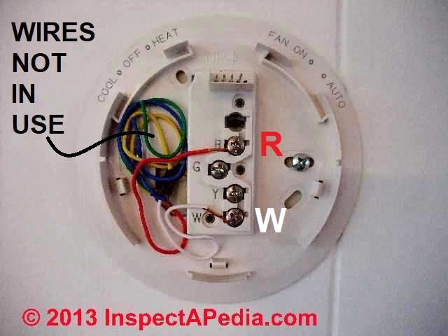
Thermostat wiring connections for the Azel i-Link multi-zone switching relay used to control HVAC equipment.
This article gives a table showing the proper wire connections for the Azel i-Link room thermostat used to control heating or air conditioning equipment.
This article series explains the basics of wiring connections at the thermostat for heating, heat pump, or air conditioning systems.
Page top image: an Azel i-Link three zone controller used to control hydronic heating zone circulator pumps.
InspectAPedia tolerates no conflicts of interest. We have no relationship with advertisers, products, or services discussed at this website.
- Daniel Friedman, Publisher/Editor/Author - See WHO ARE WE?
Azel i-Link Multi-Zone Switching Relay Wiring Details
Azel Technologies is a Canadian heating controller manufacturer that provides installation instructions and wiring diagrams for their controllers, including Excerpting from Azel's i-Link installation instructions given below as a PDF. Excerpting:
The i-Link series multi-zone circulator controller is operated by low voltage thermostats or any other low voltagecontrollers having an SPST switching action.
The i-Link controller provides intermediate switching to permit up to six circulators and a boiler operating control in a multi-zone hydronic heating system.
As an example of use of this relay, when installing a radiant floor heating system that uses a controller, the additional thermostats must be wired to instruct that controller to send heat to their zones.
Azel multi-zone switching relays are sold in five models, differering simply in the number of heating zones to be controlled, as we list here:
- SP-82 2 Zone Switching Relay
- SP-83 3 Zone Switching Relay
- SP-84 4 Zone Switching Relay
- SP-85 5 Zone Switching Relay
- SP-86 6 Zone Switching Relay
Contact Azel Technologies
- Azel Technologies Inc., P.O. Box 53138 10 Royal Orchard Blvd. Thornhill, Ontario, Canada L3T 7R9 Ph: 905-223-5567 Fax: 905-223-3778 Email: info@azeltec.com, Website: www.azeltec.com.
- ZEL i-LINK SP82/83.84/85/86 INSTALLATION & OPERATING INSTRUCTIONS [PDF] that include detailed installation and wiring procedures and connections. We'll include an example below.
...
Azel Thermostat Terminal Identification |
|
| Line Voltage Terminals | |
| Terminal ID | Function |
| N | 120 VAC Neutral Terminal Input |
| L | 120 VAC Hot Terminal Input |
| ZC | Usage depends on Cold start or Tankless Coil. Application. Refer to wiring diagrams for details. |
| ZR | |
| SYS PMP/N | L 120 VAC System Circulator Power |
| ZONE 1/N | L Zone 1 120VAC Circulator Power |
| ZONE 2/N | L Zone 2 120VAC Circulator Power |
| ZONE 3/N | L Zone 3 120VAC Circulator Power |
| ZONE 4/N | L Zone 4 120VAC Circulator Power |
| ZONE 5/N | L Zone 5 120VAC Circulator Power |
| ZONE 6/N | L Zone 6 120VAC Circulator Power |
| Dry Contact Terminals | |
| Terminal ID | Function |
| X | ZX Dry Contact End Switch |
| Low Voltage Terminals | |
| Terminal ID | Function |
| OUTPUT/COM | 24 VAC transformer common |
| OUTPUT/24VAC | 24 VAC transformer hot |
| ZONE EXPANSION/1 2 3 4 | ZONE expansion to additional i-Link Controls |
| Thermostat Terminals | |
| Terminal ID | Function |
| RT/1 | Zone 1 24VACThermostat HotTerminal |
| W/T1 | Zone 1 Thermostat SwitchingTerminal |
| RT/2 | Zone 2 24VACThermostat HotTerminal |
| W/T2 | Zone 2 Thermostat SwitchingTerminal |
| RT/3 | Zone 3 24VACThermostat HotTerminal |
| W/T3 | Zone 3 Thermostat SwitchingTerminal |
| RT/4 | Zone 4 24VACThermostat HotTerminal |
| W/T4 | Zone 4 Thermostat SwitchingTerminal |
| RT/5 | Zone 5 24VACThermostat HotTerminal |
| W/T5 | Zone 5 Thermostat SwitchingTerminal |
| RT6 | Zone 6 24VACThermostat HotTerminal |
| W/T6 | Zone 6 Thermostat SwitchingTerminal |
Notes to the table above
- Source: AZEL i-LINK SP82/83.84/85/86 INSTALLATION & OPERATING INSTRUCTIONS [PDF] where you will find complete installation details for your Azel i-Link relay control
Example wiring details from the instructions above.
Watch out: this example is for a cold start (low thermal mass) boiler application. Your requirements and equipment may differ - see the instructions.

Excerpt: Operation:
When zone thermostat calls for heat, the appropriate circulator is actuated and the isolated end switch X-X will start the boiler. A system circulator is also actuated if it is installed.
Excerpt: Jumper Placement:
The jumper (factory installed) should be placed between terminal ZC and ZR. Connect isolated end switch X-X to T-T terminals on boiler control.
...
Reader Comments, Questions & Answers About The Article Above
Below you will find questions and answers previously posted on this page at its page bottom reader comment box.
Reader Q&A - also see RECOMMENDED ARTICLES & FAQs
3-zone radiant heat: Honeywell RHT2300B thermostat can't talk to Azel i-Link SP83 zone controller
I am installing a 3 zone in-floor radiant system in my home
Every thing is going well so far, except I am running into an issue where Honeywell (my T-Stat manufacture) is telling me my RHT2300B t-stat cannot be used with my in-floor zone controller (Azel i-Link sp-83) when I call their tech support hotline.
They cannot tell me why or what their letter designations mean.
I am an industrial controls electrician of 23 years, who I must confess, does not have much experience with HVAC.
All I need is a simple t-stat that sends voltage (24vac) when heat is called for to my controller and opens back up (back to zero volts) when the set-point is achieved.
I am having a hard time believing that this t-stat is not capable of doing that. Can any one help?
Eric - Eric 9/9/11
Reply: get the thermostat and controller product numbers correct and it's easy to find wiring instructions
Eric,
I found two important details in researching your question:
1. you gave me an in-valid Honeywell thermostat number, but I was able to guess at the correct one and easily obtain wiring instructions from Honeywell. Correctly your thermostat is the Honeywell 5-2 Day Programmable Thermostat - RTH2300B1012
2. For the Honeywell thermostat model that you mention, correctly named, Honeywell's instructions point out that
The [Honeywell 5-2 Day Programmable Thermostat - RTH2300B1012] thermostat cannot be used if your old thermostat had [and used] any two of the following wires: R, RC, RH, 4 and V.[5]
Call back and ask for senior service tech or service manager.
So if, when you spoke with the Honeywell service technician, and if your old thermostat included and used any two of the wire labels I quote above, then indeed, even if s/he couldn't explain why, indeed you cannot use this thermostat model for your application.
Wiring details for the Honeywell 5-2 Day Programmable thermostat are found
Help Replacing a round Honeywell T87 with a Digital Honeywell Thermostat
Hello - I am replacing a round Honeywell thermostat with a non-programmable digital Honeywell unit. I have a hot water system with multiple zones and with no air conditioning.
There are three wires at the thermostat. On the old round unit the red wire went to the R terminal, the white wire went to the w terminal and a green wire went to B terminal.
I hooked up the new stat the same way but it would not work. If I selected "fan on" instead of "fan auto" the zone would heat up but would not shut off (hot water kept flowing even if I selected a temp below room temp). Appreciate your help. - Patrick - 1/20/12
Reply:
Patrick, typically the three wire thermostat hookups would be exactly the same for the old and new thermostats.
For details of wiring a typical and simple digital Honeywell thermostat,
see HONEYWELL 5-2 DAY PROGRAMMABLE THERMOSTAT - RTH2300B1012.
For help in understanding the wiring of your old thermostat,
see THREE-WIRE HONEYWELL WALL T87-F TYPE THERMOSTAT WIRING and also
Help wiring a digital replacement for an old mercury thermostat
I am replacing an old mercury thermostat with a digital. my system is a heat pump. My neighbor gave me an Azel digital thermostat but there are no instructions, not even a box.
I'm trying to decide if this is even a heat pump compatible thermostat. on the therm it has c, g, rc, rh (which are linked by a black wire.)
w, y, b, and o. coming out of my wall is, white connected on old therm w2, yellow connected to y, green conn g, black conn e, red to r, blue to b and bro to x. any help would be great. - Kurt 6/4/12
Reply:
Kurt, For help in understanding the wiring of your old thermostat,
see THREE-WIRE HONEYWELL WALL T87-F TYPE THERMOSTAT WIRING and also
see GENERIC HVAC THERMOSTAT CONTROL WIRING POINTS
Many thermostat wiring setups are straightforward or "cookbook" but why not find the brand name on your thermostat and then you can obtain the installation instructions right from the manufacturer?
Also, Honeywell's thermostat replacement advice (and most likely that of all thermostat manufacturers) warns:
Watch out: MERCURY NOTICE: Do not put your old thermostat in the trash if it contains mercury in a sealed tube. Contact your local waste management authority for instructions regarding recycling and proper disposal.[5]
...
Continue reading at THERMOSTAT INSTALLATION STEPS or select a topic from the closely-related articles below, or see the complete ARTICLE INDEX.
Suggested citation for this web page
THERMOSTAT WIRING AZEL i-LINK at InspectApedia.com - online encyclopedia of building & environmental inspection, testing, diagnosis, repair, & problem prevention advice.
Or see this
INDEX to RELATED ARTICLES: ARTICLE INDEX to HVAC THERMOSTATS
Or use the SEARCH BOX found below to Ask a Question or Search InspectApedia
Ask a Question or Search InspectApedia
Share this article:Try the search box just below, or if you prefer, post a question or comment in the Comments box below and we will respond promptly.
Search the InspectApedia website
Note: appearance of your Comment below may be delayed: if your comment contains an image, photograph, web link, or text that looks to the software as if it might be a web link, your posting will appear after it has been approved by a moderator. Apologies for the delay.
Only one image can be added per comment but you can post as many comments, and therefore images, as you like.
You will not receive a notification when a response to your question has been posted.
Please bookmark this page to make it easy for you to check back for our response.
IF above you see "Comment Form is loading comments..." then COMMENT BOX - countable.ca / bawkbox.com IS NOT WORKING.
In any case you are welcome to send an email directly to us at InspectApedia.com at editor@inspectApedia.com
We'll reply to you directly. Please help us help you by noting, in your email, the URL of the InspectApedia page where you wanted to comment.
Citations & Reviewers
In addition to any citations in the article above, a full list is available on request.
- [4] Azel Technologies Inc., P.O. Box 53138 10 Royal Orchard Blvd. Thornhill, Ontario, Canada L3T 7R9 Ph: 905-223-5567 Fax: 905-223-3778 Email: info@azeltec.com, Website: www.azeltec.com.
- [2] Thanks to reader S.R. for discussing loss of heat due to a thermostat wiring mistake, October 2010
- [3] Thank to Mr. Scott Meenen , G&S Mechanical Services , for providing some common thermostat wiring codes also found at Mr. Meenen's web page Malware Deleted 12/9/2014 . Mr. Meenan provides heating, heat pump, and air conditioning repair services in Maryland, Washington D.C., and northern Virginia
- [8] "Automatic Oil Burner Controls - Thermostats", Domestic and Commercial Oil Burners, 3rd Ed., Charles H. Burkhardt, McGraw Hill, 1969 (and later editions), ASIN B0000EG4Y8
- [9] Thermostat wiring color codes & conventions, Thanks to reader " Helpful Pointers" Regarding 24V T, 10/7/2012
- [10] Domestic Central Heating Wiring Systems and Controls, 2d Ed., Raymond Ward, Newnes, ISBN-10: 0750664363, ISBN-13: 978-0750664363,
- In addition to citations & references found in this article, see the research citations given at the end of the related articles found at our suggested
CONTINUE READING or RECOMMENDED ARTICLES.
- Carson, Dunlop & Associates Ltd., 120 Carlton Street Suite 407, Toronto ON M5A 4K2. Tel: (416) 964-9415 1-800-268-7070 Email: info@carsondunlop.com. Alan Carson is a past president of ASHI, the American Society of Home Inspectors.
Thanks to Alan Carson and Bob Dunlop, for permission for InspectAPedia to use text excerpts from The HOME REFERENCE BOOK - the Encyclopedia of Homes and to use illustrations from The ILLUSTRATED HOME .
Carson Dunlop Associates provides extensive home inspection education and report writing material. In gratitude we provide links to tsome Carson Dunlop Associates products and services.
 |
HOME | ABOUT | ASK a QUESTION | CONTACT | CONTENT USE POLICY | DESCRIPTION | POLICIES | PRIVACY | |
| © 2026 - 1985 Publisher InspectApedia.com - Daniel Friedman | |||||||||