 Hot Air Heating Furnaces, Controls & Switches
- POST a QUESTION or COMMENT about warm air heating system controls & switches
Furnace operating controls & switches: this article explains how to identify & set or adjust the controls and switches found on warm air heating furnace systems.
This article series answers questions about central heating system controls and switches: troubleshooting, inspection, diagnosis, and repairs.
We describe how to inspect, troubleshoot and repair heating and air conditioning systems to inform home owners, buyers, and home inspectors of common heating system defects.
InspectAPedia tolerates no conflicts of interest. We have no relationship with advertisers, products, or services discussed at this website.
- Daniel Friedman, Publisher/Editor/Author - See WHO ARE WE?
How to Identify, Reset, or Adjust Hot Air Heating System (Warm Air Furnace) Controls and Switches
 The articles listed below and found in this article series provide description of all of the major
components of warm air heating systems, how to recognize or find each component, what it looks like, what goes wrong, and how
to maintain, repair or adjust the component.
[Click to enlarge any image]
Article Series Contents
- FURNACE CONTROLS & SWITCHES
- BLOWER DOOR SAFETY SWITCH
- CAD CELL RELAY SWITCH
- DRAFT REGULATORS / HOODS GAS HEATERS - gas heaters
- DRAFT REGULATOR, DAMPER, BOOSTER - oil & other heaters
- ELECTRIC MOTOR OVERLOAD RESET SWITCH
- ELECTRICAL POWER SWITCH FOR HEAT
- FAN AUTO ON CONTROLS
- FAN LIMIT SWITCH
- FIRE SAFETY CONTROLS
- RESET SWITCH on PRIMARY CONTROL
- FLUE GAS SWITCH INSTALLATION & WIRING
- FLUE GAS SPILL SWITCH SOURCES & SELECTION
- FLUE GAS SPILL SWITCH TRIPPING & RESET
- FLUE SPILL SWITCH & COMBUSTION AIR TESTS
- STACK RELAY SWITCH
- THERMOCOUPLE REPAIR / REPLACEMENT - gas burner safety control
Comparing Forced Hot Air Heat with Gravity Hot Air Heating Systems
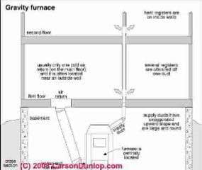
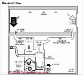
The sketches at above and at above left left are provided courtesy of Carson Dunlop Associates, explains the basics of how a modern warm air heating system or "furnace" works and shows how warm air flows in a building.
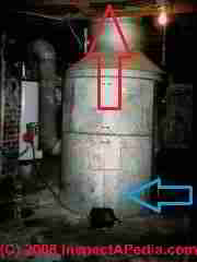
The Carson Dunlop sketch at right shows how an older gravity heating system worked, such as the "octopus" france shown at the top of this page.
This article provides details about the operation, controls, inspection, diagnosis, and repair of all types of warm air heating furnaces.
What is the Function of the Hot Air Furnace Fan Limit Switch?
Details about the fan limit switch, how it works, and how it is set are provided
at FAN LIMIT SWITCH. Excerpts are below.
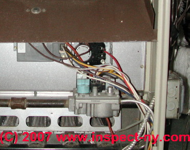
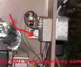
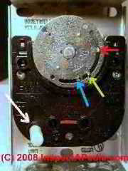 The warm air furnace fan limit switch is a control which determines when the hot air furnace blower assembly turns on and off.
The fan limit switch prevents the furnace blower from sending chilly air into the building if the oil or gas burner has not sufficiently heated up the furnace heat exchanger and supply air plenum.
In our gas furnace control photographs above we show to illustrations of a hot air furnace fan limit switch as you're likely to find one at a typical furnace.
A fan limit switch on an oil fired furnace is shown the right hand photo above and a close up is shown at left.
The fan limit switch is about in the center of the above photo, and is partially hidden by a low voltage transformer and a metal electrical junction box which are mounted at the right side of the furnace cabinet.
The fan limit switch is also a safety control which protects the furnace heat exchanger from damage by turning the burner offOn the furnace gas or oil burner if the temperature inside the warm air supply plenum (just above or just next to the heat exchanger) gets too high.
Details about the fan limit switch, how it works, and how it is set are provided
at FAN LIMIT SWITCH where we provide a series of installation, wiring, diagnostic & repair articles including
FAN LIMIT SWITCH FAQs.
A Quick Guide to Oil Burner and Gas Burner Flame Sensors
Furnace Oil-burners use either a cad cell or stack relay to confirm that the furnace oil burner is operating properly and to avoid flooding the combustion chamber with un-burned oil.
Where are the all the forced warmair heating system reset buttons? If you are looking for the main reset button on heating equipment you'll want to see:
BLOWER DOOR SAFETY SWITCH - shuts off power to the air handler if the blower compartment door is opened
CAD CELL RELAY SWITCH (hot water boilers and some water heaters),
STACK RELAY SWITCH On older oil fired boilers and furnaces, shuts off the system if stack temperature is too low (soot clogging for example) or too high (unsafe)
FLUE GAS SPILL SWITCH TRIPPING & RESET (gas fired equipment), shut down gas fired equipment if there is combustion gas spillage
At ELECTRIC MOTOR OVERLOAD RESET SWITCH we discuss the thermal overload switch and reset button that is found on many electric motors including those operating air conditioning fans, heating system oil burners, and furnace blowers and motors.
A Guide to Oil Fired Furnace or Heating Boiler Cad Cell Relays
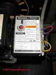
Flame sensing devices on oil-fired heating appliances: modern oil-fired heating furnaces, boilers, and water heaters use a Cadmium Cell sensor, usually located inside the oil burner tube, to "see" the presence of flame and thus to assure that the oil burner assembly stops pumping oil into the combustion chamber if flame ignition is unsuccessful.
The cad cell itself, that is the little cell that "sees" the oil burner flame, is wired (often by a yellow wire) to the cad cell relay switch (see photo) which is usually a gray box with a red "reset" button located on top of or alongside the the oil burner assembly.
The cad cell causes the relay to switch the oil burner off when a flame is not established or if flame is lost at the oil burner.
Our photograph shows a modern Honeywell(R) R8184G 4009 cad cell relay for use on (typical) intermittent ignition oil burner equipment.
Details about Cad Cell relay switches, how to inspect, test, and reset them can be read
at CAD CELL RELAY SWITCH
A Guide to Stack Relay Control Switches on Boilers, Furnaces, or Water Heaters
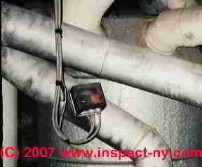
Oil Burner Stack Relay Switches Explained Older oil burners used to heat a warm air furnace, a heating boiler, or a water heater may use a Stack Relay to prevent sending fuel into the heater if it has not been successfully ignited.
Stack relays are an older type of flame sensor than the Cad Cell Relays which we discussed above, but they accomplish the same purpose (turn off the oil burner if the flame is not established).
The "stack relay" is a bimetallic spring inserted into the flue vent connector located usually quite close to the heating boiler between the boiler top and the chimney. The bimetallic spring warms in response to hot oil burner exhaust, confirming that combustion is taking place.
If combustion is not occurring a timer inside the stack relay turns off the oil burner to prevent flooding of the combustion chamber with un-burned oil.
We provide details about stack relays, the function, inspection, testing, and setting of stack relay switches
at STACK RELAY SWITCH
Guide to Draft Hoods on Gas Fired Furnaces, Boilers, Water Heaters - Purpose, Inspection, Repair
What is a Gas Appliance, Furnace, Water Heater, or Boiler Draft Hood
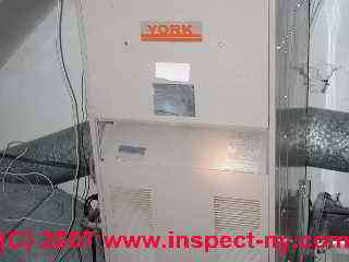
The photo at left is of a York gas fired furnace which displays a conventional draft hood opening - the large horizontal opening space shown in the middle of the furnace.
The purpose of this opening is to permit additional air to flow into the flue vent connector (stack pipe) and chimney when the gas burner is operating.
This additional air flow avoids excessive draft at the gas burner. Too much draft at the gas burner could result in improper gas combustion. (The gas burner will be below this opening and behind the cover with the louvered openings.
The louvers provide combustion air to the gas burner.)
The draft hood or draft regulating device we are discussing here is normally used only on gas-fired heating equipment, not on oil-fired equipment.
Details about draft control for gas fired heating systems, including furnaces (like the furnace shown in our photo above) or boilers, are discussed
at DRAFT REGULATORS / HOODS GAS HEATERS On gas fired equipment.
(Details about draft control on oil fired heating systems, including furnaces or boilers, are discussed
at DRAFT REGULATOR, DAMPER, BOOSTER barometric dampers on oil fired equipment.)
Guide to Flue Gas Spill Switches on gas fired equipment
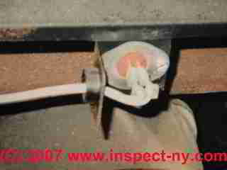
What is a furnace, boiler, or water heater flue gas spill switch?
A spill switch may be found at the draft hood on any modern gas fired appliance, such as a heating furnace (hot air heat), a heating boiler (hot water heat or steam heat), or a water heater.
This little sensor, or two or more of them, form an important safety device that feels the heat of escaping combustion gases that ought to be going up the flue or chimney.
Since escaping combustion gases in a building are dangerous (forming a potentially fatal carbon monoxide hazard), if the sensor gets hot from flue gases flowing past its surface, it is designed to turn off the fuel supply to the gas burner.
Details about flue gas spill switches used on gas-fired appliances such as furnaces and water heaters can be read
at FLUE GAS SPILL SWITCH TRIPPING & RESET
Guide to Inspecting Barometric Dampers or Draft Regulators on Oil Fired Furnaces, Boilers,
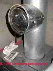
Barometric dampers are devices used to regulate the draft on oil-fired heating equipment such as furnaces, boilers, or water heaters.
On oil fired equipment the barometric damper, or draft regulator is typically a round Tee inserted in the flue vent connector between the heating appliance and the chimney.
The face of the tee contains a round "door" with an adjustable weight. The service technician adjusts the weight to control the swing or opening of this door which in turn controls the amount of excess air that can enter the flue and chimney when the oil burner is operating.
The barometric damper or draft regulating device we are discussing here is normally used only on oil-fired heating equipment, not on gas-fired equipment.
Details about draft control on oil fired heating systems (such as the oil fired heater shown in the photo at left), including furnaces or boilers, are discussed
at DRAFT REGULATOR, DAMPER, BOOSTER barometric dampers on oil fired equipment.
(Details about draft control for gas fired heating systems, including furnaces or boilers, are discussed
at DRAFT REGULATORS / HOODS GAS HEATERS On gas fired equipment.)
If you don't know what kind of heat your building uses, we explain how to figure out the answer
If your heating system is not working properly,
see NO HEAT - BOILER - gravity or forced hot water heat: baseboards, radiators, convectors
or
NO HEAT - FURNACE - forced warm air heat
...
Continue reading at BLOWER DOOR SAFETY SWITCH or select a topic from the closely-related articles below, or see the complete ARTICLE INDEX.
Or see these
Recommended Articles
- A/C & HEAT PUMP OPERATING CONTROLS
- AIR CONDITIONING & HEAT PUMP CONTROLS & SWITCHES
- COOLING & HEATING CONTROL & SWITCH INDEX
- ELECTRICAL POWER SWITCH FOR HEAT
- FURNACE CONTROLS & SWITCHES
- HEAT WON'T TURN OFF
- HEAT WON'T TURN ON
- MANUALS & PARTS GUIDES - HVAC - home - Master Index to All Brand Names & HVAC manuals, wiring diagrams, installation and repair guides
- OIL BURNER MANUALS
- MANUALS for HEATING & A/C SYSTEM CONTROLS
Suggested citation for this web page
FURNACE CONTROLS & SWITCHES at InspectApedia.com - online encyclopedia of building & environmental inspection, testing, diagnosis, repair, & problem prevention advice.
Or see this
INDEX to RELATED ARTICLES: ARTICLE INDEX to HEATING FURNACES
Or use the SEARCH BOX found below to Ask a Question or Search InspectApedia
Ask a Question or Search InspectApedia
Questions & answers or comments about warm air heating system controls & switches
Try the search box just below, or if you prefer, post a question or comment in the Comments box below and we will respond promptly.
Search the InspectApedia website
Note: appearance of your Comment below may be delayed: if your comment contains an image, photograph, web link, or text that looks to the software as if it might be a web link, your posting will appear after it has been approved by a moderator. Apologies for the delay.
Only one image can be added per comment but you can post as many comments, and therefore images, as you like.
You will not receive a notification when a response to your question has been posted.
Please bookmark this page to make it easy for you to check back for our response.
IF above you see "Comment Form is loading comments..." then COMMENT BOX - countable.ca / bawkbox.com IS NOT WORKING.
In any case you are welcome to send an email directly to us at InspectApedia.com at editor@inspectApedia.com
We'll reply to you directly. Please help us help you by noting, in your email, the URL of the InspectApedia page where you wanted to comment.
Citations & References
In addition to any citations in the article above, a full list is available on request.
- Domestic and Commercial Oil Burners, Charles H. Burkhardt, McGraw Hill Book Company, New York 3rd Ed 1969.
- National Fuel Gas Code (Z223.1) $16.00 and National Fuel Gas Code Handbook (Z223.2) $47.00 American Gas Association (A.G.A.), 1515 Wilson Boulevard, Arlington, VA 22209 also available from National Fire Protection Association, Batterymarch Park, Quincy, MA 02269. Fundamentals of Gas Appliance Venting and Ventilation, 1985, American Gas Association Laboratories, Engineering Services Department. American Gas Association, 1515 Wilson Boulevard, Arlington, VA 22209. Catalog #XHO585. Reprinted 1989.
- "Warm Air Heating Systems". Instructional Technologies Institute, Inc., 145 "D" Grassy Plain St., Bethel, CT 06801 800/227-1663 [home inspection training material] 1987
- Heating, Ventilating, and Air Conditioning Volume I, Heating Fundamentals,
- The ABC's of Retention Head Oil Burners, National Association of Oil Heat Service Managers, TM 115, National Old Timers' Association of the Energy Industry, PO Box 168, Mineola, NY 11501. (Excellent tips on spotting problems on oil-fired heating equipment. Booklet.)
- Thanks to reader Eric Haver for technical edits 3/24/2009
- Our recommended books about building & mechanical systems design, inspection, problem diagnosis, and repair, and about indoor environment and IAQ testing, diagnosis, and cleanup are at the InspectAPedia Bookstore. Also see our Book Reviews - InspectAPedia.
- In addition to citations & references found in this article, see the research citations given at the end of the related articles found at our suggested
CONTINUE READING or RECOMMENDED ARTICLES.
- Carson, Dunlop & Associates Ltd., 120 Carlton Street Suite 407, Toronto ON M5A 4K2. Tel: (416) 964-9415 1-800-268-7070 Email: info@carsondunlop.com. Alan Carson is a past president of ASHI, the American Society of Home Inspectors.
Thanks to Alan Carson and Bob Dunlop, for permission for InspectAPedia to use text excerpts from The HOME REFERENCE BOOK - the Encyclopedia of Homes and to use illustrations from The ILLUSTRATED HOME .
Carson Dunlop Associates provides extensive home inspection education and report writing material. In gratitude we provide links to tsome Carson Dunlop Associates products and services.


