
InspectAPedia® FREE Encyclopedia of Building & Environmental Construction, Diagnosis, Maintenance & Repair |
Question? Just ask us! InspectAPedia
|
 Plumbing System Layout Plan
Chapter 13 of How to Build Your Dream Home © 2020 InspectApedia.com
- POST a QUESTION or COMMENT about how to identify the architectural style of buildings and building components
This article series provides an updated version of Hubbard Cobb's Your Dream Home, illustrated by Sigman-Ward, first published by Wm. H. Wise & Co. New York, 1950.
From site selection and obtaining financing through each step in construction of a single family home the simple procedures and drawings in this book are still useful for anyone building or repairing a home or other small structure.
InspectAPedia tolerates no conflicts of interest. We have no relationship with advertisers, products, or services discussed at this website.
- Daniel Friedman, Publisher/Editor/Author - See WHO ARE WE?
Installing the Plumbing System
Before you can do much in the way of getting the plumbing system installed, you must obtain the roughing in measurements for the type of fixtures that you are going to install.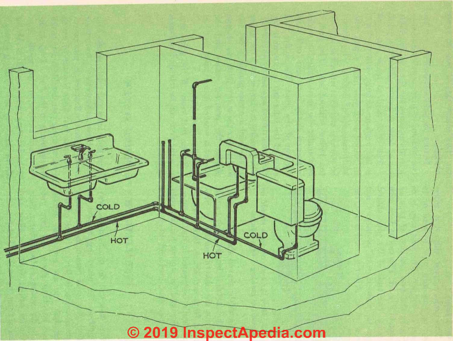
Fig. 33. Layout for the fresh-water supply system.
These roughing plans (plumbing rough-in plans) will give you all the dimensions of the fixtures, their minimum height from the floor and distance from the wall, and the location of the holes in the wall and floor for the supply lines and waste pipes. You can get these measurements from your dealer when the fixtures are purchased.
If your first floor is made of wood, the first thing you should do is to make the openings in the floor of the bathroom and kitchen so that waste lines to the fixtures can be brought in.
This is a section of Chapter 13 of BUILD YOUR DREAM HOME at InspectApedia.com - online encyclopedia of building & environmental inspection, testing, diagnosis, repair, & problem prevention advice.
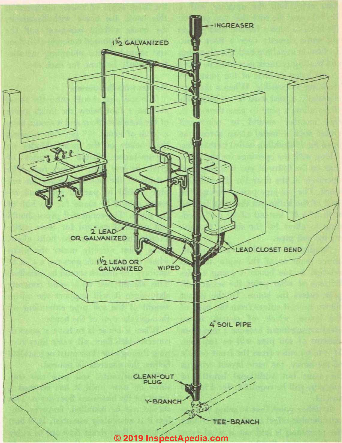
Fig. 34. Layout for connections to the soil stack.
Holes can be made by first drilling through the flooring with a brace and bit and then expanding the opening with a keyhole saw. Be sure that you position the holes in such a fashion that you do not come directly over a floor joist. In fact, in installing both the plumbing and heating systems, care must be taken to cut away as little of the joists and studding as possible.
When a stud or, especially, a floor joist or ceiling joist must be cut back a little to allow a pipe to pass through it, this member should be reinforced either with a metal strap across the opening or studding nailed to the sides.
Along with the openings for the waste lines to the fixtures, you will also need openings in the floor for the soil-pipe stack. The soil pipe passes through the wall of the bathroom that was framed with 2" x 6" instead of 2" x 4" studding to allow for the size of the hub on the soil pipe.
Needless to say, the location of the street main or of the septic tank in relation to the house is going to determine at what point the sewer soil- pipe enters the house. In the layout shown here, it enters from the back of the house, which, of course, is an ideal arrangement because a minimum amount of soil pipe will be required.
If it must enter from the front or side of the house, the basic layout remains the same but additional lengths of soil pipe will be required. See Figs. 33 and 34.
Another point that is going to have considerable effect on the manner that the plumbing is laid out is what type of foundation the house rests upon.
For the purpose of clarity, let us take the three types of houses discussed in this book, the house with basement, the house without basement and the house with a poured concrete-slab floor and show how the plumbing installation should be done for each one.
Plumbing Design & Installation for Homes with Basements
The soil pipe should enter the house at least 1 foot below the finish grade of the basement floor and it should have a pitch of about 1/4" per foot towards the outside of the house. Under no circumstances should this pitch or grade be less than 1/8" per foot. Plumbing drains with less than 1/8" of fall per foot of horizontal run will clog repeatedly, risking a costly sewage backup and spill in the building.
The bottom of the trench dug for the soil pipe should be packed solid and recesses should be made for the hub of the pipes. The connected pipes should rest on solid ground for their entire length and never on the hubs alone.
At a point directly under the point where the vent stack goes up, a 4" x 4" sanitary tee-branch should be installed. This should rest on a solid concrete slab, since it will support the entire weight of the soil pipe extending up through the roof of the house.
When a house is to have a poured-concrete-slab floor, all waste lines running through the floor must be installed before the concrete is poured.
The horizontal soil pipe can continue on now until it has reached a point for the basement floor drain. This should not be installed, however, unless it is absolutely essential. It is best to have a floor drain flow out to a dry well rather than into the sewer line. If the drain must discharge into the sewer line, the drain should be fitted with a deep-seal trap.
The first vertical piece of soil pipe coining off the sanitary tee-branch is a Y branch. One side of this is fitted with a brass clean-out plug so that, in the event the sewer line should become clogged, there will be an opening into it at a convenient location. If you are not going to have a basement floor drain, the end of the sanitary tee-branch can be plugged to serve as a clean-out.
Rooftop Soil Pipe Vent Flashing
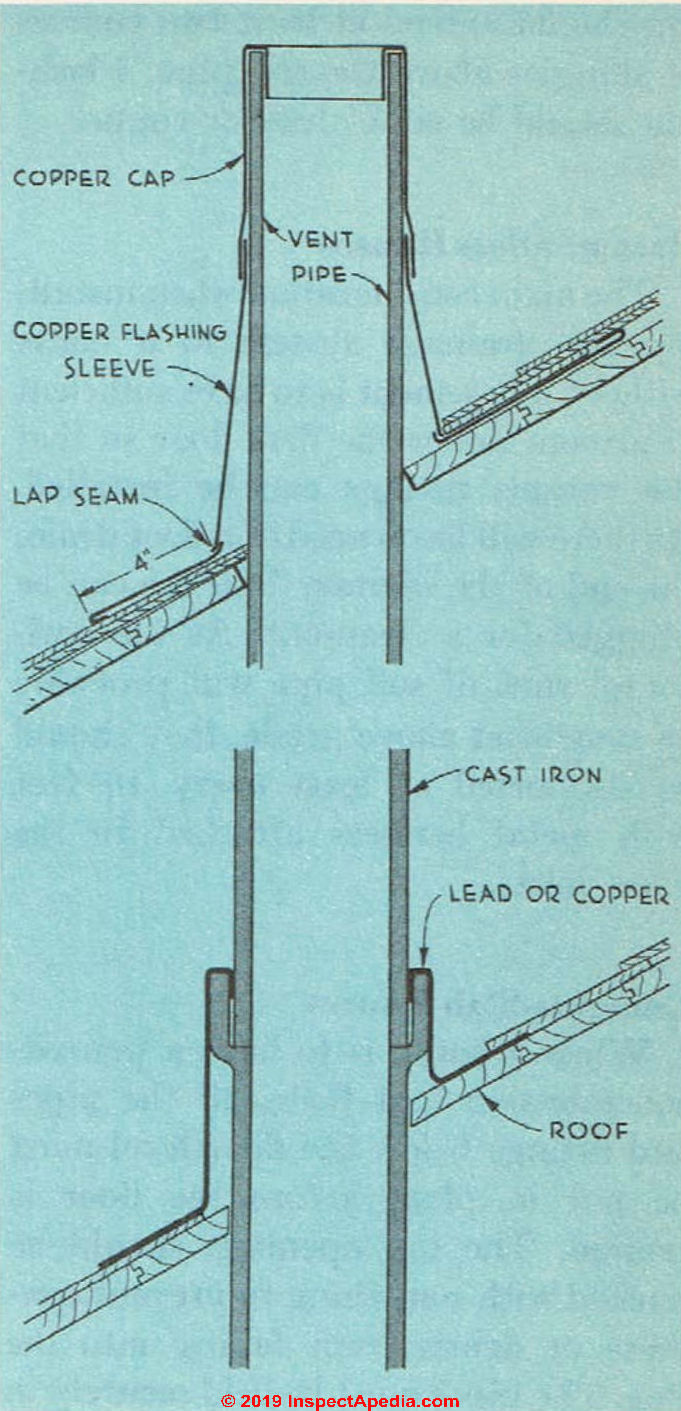
Fig. 35. Several methods of flashing around the soil pipe at the roof.
The vertical stack can continue up again until it arrives at the spot for installing the branch to take care of the toilet, bathtub and washbasin drains. This branch is a double-topped T with a 2" tapping. The next section is a 4" x 2" tapped sanitary tee.
The soil stack continues up farther until you reach the point where a 4" tapped sanitary tee is installed for the vent line from the fixtures. The exact location of this tee will depend on what future plans you have for the attic.
If a bathroom is going to he installed later on, this fitting should be installed above the highest fixture in the attic bath, and you will also need a double-topped sanitary tee at the bathroom floor level for the future additional fixtures. The openings in this tee should be capped until it is ready to be put into use.
In cold climates, special care must be taken with the portion of the soil pipe that is above the roof in order to prevent frost from forming inside the pipe and blocking it up. One method of doing this is to increase the size of the pipe by means of an increaser. The increase in size should take place at least 12 inches below the roof.
The opening between the roof and the soil pipe must be carefully flashed to prevent leaking. Fig. 3.5 shows several methods of flashing. The flashing should extend at least two courses of shingles above the soil pipe. Flashing should he either lead or copper.
Plumbing Drain Design for Basementless Houses
The main consideration when installing the drainage system in a house without a basement is to have sufficient headroom under the first floor so that the various fittings can be installed.
As there will be no need of a floor drain, the end of the sanitary base tee can be plugged for a clean-out. As the horizontal runs of soil pipe will probably be somewhat above grade, they should be supported at least every 10 feet with metal hangers attached to the floor joists.
Plumbing Drain Design for Concrete-Slab Houses
When a house is to have a poured-concrete-slab first floor, all the pipes and fittings below the floor level must be put in place before the floor is poured. The top openings should be packed with something to prevent concrete or debris from falling into the line.
The pipes must be held securely in place so that there will be no chance of their being moved out of position by the fresh concrete. The pipes themselves should not be encased in the concrete. Slip loosely fitting metal sleeves around them before the concrete is poured.
Pipes and fittings that are to be covered with concrete must be especially durable as it will be almost impossible to replace them. Cast iron, copper, brass and [no longer lead] are suitable.
Plumbing Fresh Water Supply Piping
You will find that installing the fresh water system is a simple business compared to the drainage system.
Fig. 33. Layout for the fresh-water supply system.
Fig. 33 shows the layout of these lines for houses with first floors and those with concrete slab floors. There will be no radical difference in the lines between houses with basements and those without basements.
The only exception would be when the hot-water heater is installed in the basement rather than in the utility room. If a hot-water or steam-heating system is used, the boiler can be fitted with special equipment to heat the hot-water supply for domestic use.
Both the hot and cold water lines are given a slight pitch, and the lowest point of each system is fitted with a plug so that the lines can be easily drained to prevent them from freezing if the house should be left without heat. Considerable fuel can be. saved if the hot-water pipes are insulated.
When bringing the supply lines to the bathroom lavatory, the cold-water line should be placed so that when the fixture is connected up, the faucet on the user’s left will be the cold water.
All lines should be given proper support in the manner described earlier in this chapter. Pipes that are not secure will vibrate when water under pressure flows through them, and in time the joints will open up and leak.
As soon as the lines are in, the rough walls around the bathtub can be put in and the tub installed.
The lavatory, kitchen sink and water closet will go in later, after all the walls have been completed. The lavatory should stand about 30 inches off the finished floor.
...
Continue reading at PLUMBING FIXTURE INSTALLATION BATH KITCHEN - next section of this chapter, or go to book contents at BUILD YOUR DREAM HOME, or select a topic from the closely-related articles below, or see the complete ARTICLE INDEX.
This entire chapter is also available as PLUMBING SYSTEM INSTALLATION [eBook], or as a PDF image at THE HOUSE PLUMBING SYSTEM [PDF] original page images.
Or see these sections of Chapter 13 - PLUMBING SYSTEM INSTALLATION
- PROPER PLUMBING WORK is IMPORTANT
- WATER SUPPLY SOURCES
- TYPES of PIPING MATERIALS
- COPPER PIPE INSTALLATION
- COPPER FLARE CONNECTIONS
- PIPE SIZE SELECTION
- CAST IRON PIPE INSTALLATION
- PLUMBING SYSTEM LAYOUT PLAN
- PLUMBING FIXTURE INSTALLATION BATH KITCHEN
- WATER HEATERS & TANKS
- PLUMBING SYSTEM PRESSURE TESTS
- SEPTIC TANK, DRAINFIELD INSTALLATION
- PLUMBING MATERIALS LIST for the basic house
Or see these
Recommended Articles
>- BATH & KITCHEN DESIGN GUIDE - home
- BUILD YOUR DREAM HOME
- PLUMBING VENT DISTANCES & ROUTING
- SEPTIC CLEARANCE DISTANCES
- SEPTIC TANK DESIGN DEPTH
- SEPTIC TANK, DRAINFIELD INSTALLATION
- SUPPLY PIPING - home
- WATER SUPPLY & DRAIN PIPING - home
Suggested citation for this web page
PLUMBING SYSTEM LAYOUT PLAN at InspectApedia.com - online encyclopedia of building & environmental inspection, testing, diagnosis, repair, & problem prevention advice.
Or see this
INDEX to RELATED ARTICLES: ARTICLE INDEX to PLUMBING SYSTEMS
Or use the SEARCH BOX found below to Ask a Question or Search InspectApedia
Ask a Question or Search InspectApedia
Questions & answers or comments about how to identify the architectural style of buildings and building components
Try the search box just below, or if you prefer, post a question or comment in the Comments box below and we will respond promptly.
Search the InspectApedia website
Note: appearance of your Comment below may be delayed: if your comment contains an image, photograph, web link, or text that looks to the software as if it might be a web link, your posting will appear after it has been approved by a moderator. Apologies for the delay.
Only one image can be added per comment but you can post as many comments, and therefore images, as you like.
You will not receive a notification when a response to your question has been posted.
Please bookmark this page to make it easy for you to check back for our response.
IF above you see "Comment Form is loading comments..." then COMMENT BOX - countable.ca / bawkbox.com IS NOT WORKING.
In any case you are welcome to send an email directly to us at InspectApedia.com at editor@inspectApedia.com
We'll reply to you directly. Please help us help you by noting, in your email, the URL of the InspectApedia page where you wanted to comment.
Citations & References
In addition to any citations in the article above, a full list is available on request.
- In addition to citations & references found in this article, see the research citations given at the end of the related articles found at our suggested
CONTINUE READING or RECOMMENDED ARTICLES.
- Carson, Dunlop & Associates Ltd., 120 Carlton Street Suite 407, Toronto ON M5A 4K2. Tel: (416) 964-9415 1-800-268-7070 Email: info@carsondunlop.com. Alan Carson is a past president of ASHI, the American Society of Home Inspectors.
Thanks to Alan Carson and Bob Dunlop, for permission for InspectAPedia to use text excerpts from The HOME REFERENCE BOOK - the Encyclopedia of Homes and to use illustrations from The ILLUSTRATED HOME .
Carson Dunlop Associates provides extensive home inspection education and report writing material. In gratitude we provide links to tsome Carson Dunlop Associates products and services.
 | HOME | ABOUT | ASK a QUESTION | CONTACT | CONTENT USE POLICY | DESCRIPTION | POLICIES | PRIVACY | |
| © 2025 - 1985 Publisher InspectApedia.com - Daniel Friedman | |||||||||