 Guide to Roof & Wall Flashing
Foundation Flashing & Roof-Wall Flashing for Building Exteriors
- POST a QUESTION or COMMENT about how to install wall, foundation, & roof-wall flashing on buildings
Building wall flashing materials, choices, installation details & specifications:
This article provides details of foundation tops, building walls, exterior trim, wall corners, and roof-wall intersection flashing to prevent leaks & water damage.
We describe the different flashing materials that can be used, how and where flashing should be installed at various building wall intersections and corners, at the intersection of a roof and building wall, at other locations, and how to seal these locations against leaks or insect damage.
InspectAPedia tolerates no conflicts of interest. We have no relationship with advertisers, products, or services discussed at this website.
- Daniel Friedman, Publisher/Editor/Author - See WHO ARE WE?
Guide to Wall Flashing Details on buildings
 This article series discusses best practices construction details for building exteriors, including water and air barriers, building flashing products & installation, wood siding material choices & installation, vinyl siding, stucco exteriors, building trim, exterior caulks and sealants, exterior building adhesives, and choices and application of exterior finishes on buildings: paints, stains.
Article Contents
- WALL FLASHING MATERIAL CHOICES
- ALUMINUM FLASHING for WALLS
- COPPER FLASHING USE on BUILDINGS
- LEAD-COATED COPPER FLASHING USE on BUILDINGS
- LEAD FLASHING USES on BUILDINGS
- BUILDING SIDEWALL FLASHING DETAILS
- TERMITE SHIELD FLASHING at BUILDING FOUNDATION WALLS
- WATER TABLE TRIM FLASHING DETAILS at WALLS
- CRITICAL FLASHING DETAILS at DECKS & PORCHES
- WALL CORNER FLASHING DETAILS
- WALL-ROOF INTERSECTION FLASHING DETAILS
This article series includes excerpts or adaptations from Best Practices Guide to Residential Construction (Steve Bliss, J Wiley & Sons) , by Steven Bliss, courtesy of Wiley & Sons.
Wall flashings are required at openings, corners, intersections, and wherever a roof terminates into a wall. While peel-and-stick tapes have replaced these flashings at many details, metal flashings are still preferred for many standard details and applications where the flashing is visible or needs to hold a shape or serve as a drip edge.
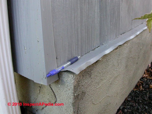
Our photo of foundation top flashing (above) shows a couple of problems: the foundation extended past the building wall, forming a shelf that invites leaks as rain runs down the building wall. The metal flashing placed on wall top slopes back towards the building, directing water inside the structure. Details like this risk rot and insect damage to the structure.
Maybe, in this case, the flashing extends "upwards" behind the building siding, forming a zee-shape that might reduce this risk. Without further inspecting we don't know. You need Zee flashing at this location, properly sloped to drain away from the building. Also
see DRIP EDGE FLASHING for ROOFS
for examples of a drip edge profile that might be adapted to the vertical portion of the foundation flashing vertical edge to improve its performance.
Wall Flashing Material Choices
Choose metal flashings that are compatible with the adjoining building materials and are at least as durable as the siding and roofing materials where they are to be placed. (See “Galvanic Corrosion” for information on metal compatibility.)
Aluminum Flashing used at building walls, properties of
Most residential wall flashing today is made from light-gauge aluminum coil stock. Aluminum is inexpensive, easy to bend, and holds paint well. However, it tends to oxidize and pit in salty or polluted air and, if unpainted, will corrode from contact with masonry due to the lime and acids.
Aluminum cannot be soldered. If using aluminum, use at least .029-inch coil stock, preferably anodized or pre finished, which is much more resistant to corrosion.
Copper Flashing on buildings, properties, uses, installation, oxidation
When the budget allows, copper is a good choice. Copper flashings come in two types: soft and harder cold-rolled. Soft copper is very malleable and useful for molding into irregular shapes. The harder cold rolled material is a better choice for most applications, because it is stronger and more durable.
Copper flashings solder easily and offer good corrosion resistance, even in polluted air and in contact with masonry. Over time, all unpainted copper will oxidize and develop a green patina that protects the underlying copper. While most people find the patina attractive, the runoff of the green oxidation can stain siding or trim.
Some experts also caution against using copper or lead-coated copper in contact with redwood or red cedar or its runoff.
Over time, the copper surface will be etched by the acidic wood runoff. Although actual failures of copper flashings are rare, they have been reported in areas of the Northeast after 10 to 20 years of service. Acid rain, combined with exposure to runoff from red cedar or other corrosive materials, is suspected as the cause.
Lead-Coated Copper Flashing Use on buildings, properties, uses, installation
This is a sheet of copper with a lead coating on each side. Where staining of building components from runoff is a potential problem, lead-coated copper may be used, which has a less noticeable gray runoff. Also, without the lead coating, copper flashing will react with galvanized steel.
Lead Flashing Uses on buildings, properties, uses, installation
For special flashing applications where a high degree of malleability is required, lead is an option. In addition to being easily bent and molded, lead is very resistant to corrosion. Lead is relatively soft, however; so it should not be used where it will be bumped or walked on. Also, it is best if left unattached on one side; if rigidly fastened on all sides, it can tear from fatigue due to thermal movement.
-- Adapted with permission from Best Practices Guide to Residential Construction (Steve Bliss, J Wiley & Sons) .
Building Sidewall Flashing Details Avoid Leaks, Rot, Insect Damage
Windows and Door Flashings
Window and door flashings are discussed extensively separately
at WINDOW FLASHING & SEALING Guide
Using Termite Shields on Building Foundation Tops
Details about how to find and recognize insect damage on buildings and details about various methods to avoid termite attack on buildings or other wood destroying insect damage to buildings are found
at INSECT INFESTATION / DAMAGE.
Below we discuss metal termite shields, one of those methods.
Also see TERMITE SHIELDS vs TERMITICIDE for a discussion of termite shields and insect attack on buildings using foam board foundation insulation.
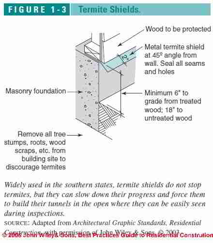
Metal termite shields are widely used atop foundations in the southern United States and in tropical climates as a physical barrier to termites. They sit directly on top of foundation walls, piers, and other supports before the first piece of wood is installed (see Figure 1-3 at left).
At one time termite shields were thought to block the entry of subterranean termites, the most widespread and destructive wood-boring insect in the United States.
However, subterranean termites, which nest in the soil, will exploit the tiniest gaps in termite shields or other barriers to reach the wooden portions of a house and will build tunnels along exposed foundation walls and around termite shields if necessary.
Although the shields do not stop termites, they slow down their progress and force them to build their tunnels in the open where they can be easily seen during inspections.
To work at all, the termite shield must have tightly sealed joints and be sealed around foundation bolts and other penetrations.
Joints can be either soldered or mechanically interlocking. If the barrier is unsealed, termites will find any small gaps and render the effort worthless.
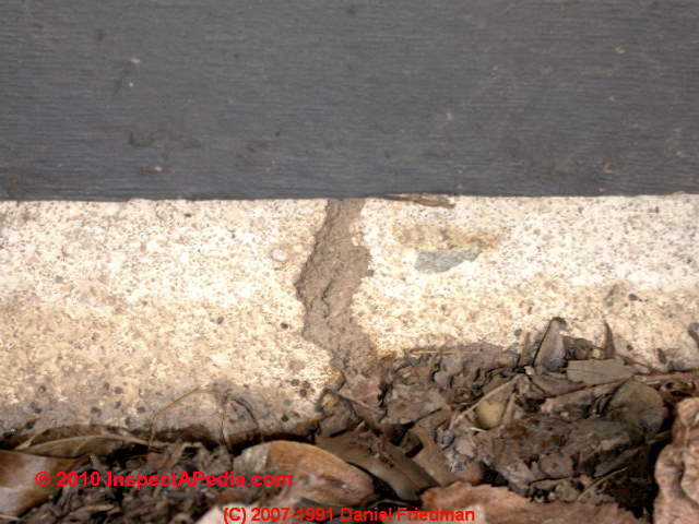
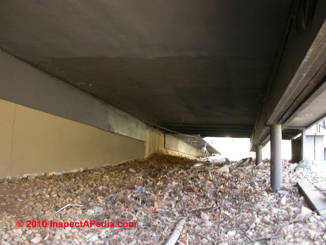
Below our termite mud tube photos show that a termite shield appears to have been installed along most but not all of the building foundation top.
Or was it? We don't know if this is wall flashing that leaves sills exposed just under the wall edge, or whether the flashing extends across the foundation to the interior (as recommended).
But our second termite photo (below right) shows a termite mud tube ascending the same foundation wall and passing under the termite shield. The shield makes it more difficult, but not impossible, for termites to attack a building.
In general, termite shields should be a minimum of 6 inches above grade and extend out 2 inches on either side of the foundation at a 45 degree angle. In addition to making termite infestations visible, they also form a capillary break between the foundation and sill.
Areas where a termite shield cannot be used, for example, where a concrete stairway abuts a foundation wall, are at high risk for termite entry.
In termite-prone regions, the only reliable way to prevent termite damage is to use treated wood in critical locations and treat the surrounding soil with termiticide.
See TERMITE SHIELDS vs TERMITICIDE for a detailed discussion of termite shields and insect attack on buildings using foam board foundation insulation.
See INSECT INFESTATION / DAMAGE for termite and other wood destroying insect information in depth, including termite inspection case reports, field photos and advice. Readers concerned about termite damage associated with foam, fiberglass, or other building insulation materials should also
Water Table Trim & Flashing Details for Building Walls
Definition of water table trim:
What is "water table trim"?
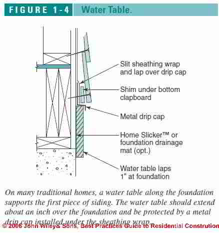
On many traditional homes, a wide board called the “water table” is installed along the foundation and supports the first piece of siding.
The water table should extend about an inch over the foundation and be capped on top with either a preformed metal drip cap or a custom-bent flashing installed under the sheathing wrap.
Cut a slit in the sheathing wrap along the entire length of the water table and slip the upper leg of the flashing under the wrap (see Figure 1-4 at left).
Critical Wall Flashing Details at Decks and Porches
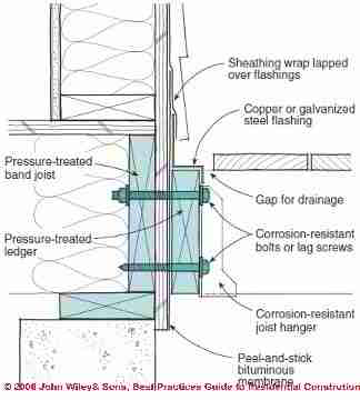
It is critical to protect against leaks and water buildup at deck ledgers, since decay in this part of a building can lead to structural failure of the deck.
At a minimum, install a cap flashing that tucks under the sheathing wrap and goes over the ledger (see Figure 4-8 at left).
Adding a second flashing, either peel-and-stick membrane or aluminum-coil stock, between the sheathing and ledger, as shown, is a worthwhile backup should any water get over, around, or through punctures in the cap flashing.
Since pressure-treated wood can be corrosive to unfinished aluminum, use coated-aluminum or galvanized steel flashing.
Also see details
Key Flashing Details at Building Wall Corners
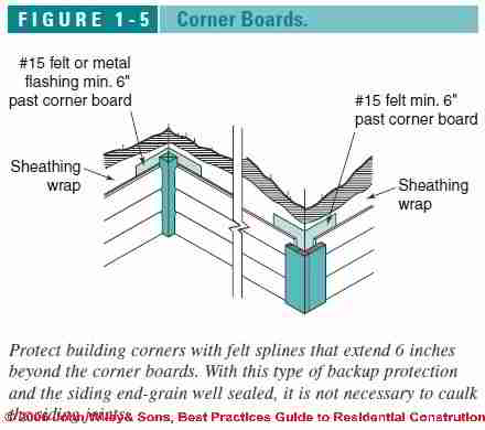
Corner boards are prone to leakage due to shrinkage of materials and wind exposure.
For simple, effective backup protection, add a spline of asphalt felt paper at outside corners so that it extends 6 inches beyond the corner boards. Inside corners also benefit from a spline (Figure 1-5 at left).
With this type of backup protection and with the end grain of the siding well sealed, it is unnecessary to caulk the siding joints at inside and outside corners.
Leaving a small gap and not caulking these joints allows any water that penetrates to dry to the exterior.
Eventually caulk joints will fail anyway, allowing water to leak in but inhibiting drying.
Guide to Step Flashing at Building Roof-Wall Intersections
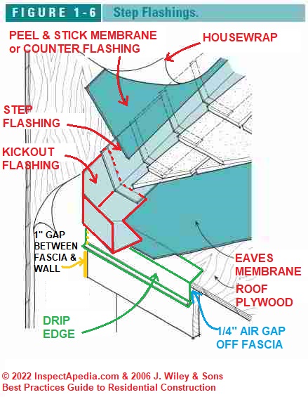
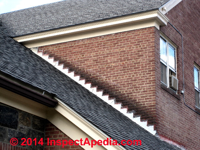
Integrate all step flashings with the sidewall-sheathing wrap by slipping the upper legs of the step flashing under the sheathing wrap (Figure 1-6 at left).
Where snow buildup is anticipated, add a band of peel-and-stick membrane over the step flashing but under the sheathing wrap, as shown.
Where the step flashing terminates along a sidewall, a preformed or custom-bent kick-out flashing is the best way to divert the water away from the siding.
Splashback Damage Protection for buildings
 In wall areas subjected to splashback,
snow buildup, or high moisture from other sources, rubberized
asphalt membranes in widths up to 36 inches can
be used to protect the wall sheathing and structure.
Water damage from splashback is common in wall sections located under the eaves of a roof with no gutters. Walls above decks or flat roofs are also prone to moisture damage from splashback or snow buildup.
In all cases, make sure to detail the flashing membrane so that it tucks under the sheathing wrap above and over the step flashing or cap flashing below. If installed along the foundation, the membrane should cover the joint where the sill meets the foundation.
The importance of roof-wall flashing and sound counter flashing is apparent in our photograph (above-left).
The absence of a gutter on the upper roof and the rain and roof runoff splash-up wear on the building wall is quite apparent.
If sound counter flashing had not been provided when this Beacon NY church was rebuilt in 1944, serious leaks would have appeared in the building interior. - Ed.
NRCA (Berg) describes the basic specifications for roof-wall abutment step flashing, based on the method described in the NRCA Roofing and Waterproofing Manual, as follows: [paraphrasing]
- Step flashing, installed as each course of shingles is installed,
involves placing an individual piece of metal flashing, bent at a right angle, against the building wall, extending up the wall 4" and onto the roof a minimum of 2" (4" is preferable) - Each step flashing piece is nailed
to the building wall only, and uses a single nail in the uppermost or top corner of each step. - Siding as counterflashing:
If the lower roof abutting the building sidewall is being installed before the building's final wall siding and water membrane are being installed, the building membrane, roofing felt on the wall, or final building siding may be able to serve as counter flashing atop the step flashing.
Watch out: because many building wall covering materials are not waterproof, depending on the siding to act as counterflashing may be unreliable. - DF - A separately-installed counterflashing
is likely to be more reliable as providing a continuous cover for the step flashing. In new construction counterflashing may be installed and sealed to the building wall using flashing tape before the finish siding is installed. See
FLASHING MEMBRANES PEEL & STICK - DF
- Adapted with permission from Best Practices Guide to Residential Construction (Steve Bliss, J Wiley & Sons) or select a topic from the closely-related articles below, or see the complete ARTICLE INDEX.
Roof Dormer Flashing Details
Moved to DORMER SIDE / ROOF FLASHING
...
...
Continue reading at DIVERTER KICK-OUT FLASHING for a description of the proper installation of a kickout flashing, or select a topic from the closely-related articles below, or see the complete ARTICLE INDEX.
Or see FLASHING WALL DETAILS FAQs - questions & answers posted originally at this page.
Or see these
Recommended Articles
- BRICK WALL LEAK REPAIRS
- DIVERTER KICK-OUT FLASHING
- DORMER SIDE / ROOF FLASHING
- FLASHING on BUILDINGS - home
- FLASHING ROOF-WALL SNAFU
- FLASHING WALL DETAILS - Roof-wall, roof-chimney & siding bottom
- FLASHING WALL to FOUNDATION or SLAB
- RAIN SPLASH-UP SIDING DAMAGE - splashback or splash-up water damage to exterior walls
- ROOF SEALANTS & MASTICS
- WALL to FOUNDATION or SLAB FLASHING
- WALL / WINDOW LEAK DIAGNOSIS
Suggested citation for this web page
WALL FLASHING DETAILS at InspectApedia.com - online encyclopedia of building & environmental inspection, testing, diagnosis, repair, & problem prevention advice.
Or see this
INDEX to RELATED ARTICLES: ARTICLE INDEX to BUILDING FLASHING
Or use the SEARCH BOX found below to Ask a Question or Search InspectApedia
Ask a Question or Search InspectApedia
Try the search box just below, or if you prefer, post a question or comment in the Comments box below and we will respond promptly.
Search the InspectApedia website
Note: appearance of your Comment below may be delayed: if your comment contains an image, photograph, web link, or text that looks to the software as if it might be a web link, your posting will appear after it has been approved by a moderator. Apologies for the delay.
Only one image can be added per comment but you can post as many comments, and therefore images, as you like.
You will not receive a notification when a response to your question has been posted.
Please bookmark this page to make it easy for you to check back for our response.
IF above you see "Comment Form is loading comments..." then COMMENT BOX - countable.ca / bawkbox.com IS NOT WORKING.
In any case you are welcome to send an email directly to us at InspectApedia.com at editor@inspectApedia.com
We'll reply to you directly. Please help us help you by noting, in your email, the URL of the InspectApedia page where you wanted to comment.
Citations & References
In addition to any citations in the article above, a full list is available on request.
- In addition to citations & references found in this article, see the research citations given at the end of the related articles found at our suggested
CONTINUE READING or RECOMMENDED ARTICLES.
- Carson, Dunlop & Associates Ltd., 120 Carlton Street Suite 407, Toronto ON M5A 4K2. Tel: (416) 964-9415 1-800-268-7070 Email: info@carsondunlop.com. Alan Carson is a past president of ASHI, the American Society of Home Inspectors.
Thanks to Alan Carson and Bob Dunlop, for permission for InspectAPedia to use text excerpts from The HOME REFERENCE BOOK - the Encyclopedia of Homes and to use illustrations from The ILLUSTRATED HOME .
Carson Dunlop Associates provides extensive home inspection education and report writing material. In gratitude we provide links to tsome Carson Dunlop Associates products and services.


