
InspectAPedia® FREE Encyclopedia of Building & Environmental Construction, Diagnosis, Maintenance & Repair |
Question? Just ask us! InspectAPedia
|
 Thermostat Wire Color Codes
& Thermostat Wiring Tips

- POST a QUESTION or COMMENT about thermostat wire color code conventions or tips & tricks of the trade in wiring thermostats
This article describes several tricks of the trade used by professionals when installing room thermostats and wiring them up. It describes the standard wire color conventions for HVAC thermostats.
InspectAPedia tolerates no conflicts of interest. We have no relationship with advertisers, products, or services discussed at this website.
- Daniel Friedman, Publisher/Editor/Author - See WHO ARE WE?
Thermostat Wiring Tips & Color Conventions for 24V Thermostats
Complete guide to thermostat wire color code convenions + 9 Wiring Tips for Room Thermostats: Helpful Pointers Regarding 24V Thermostat Wiring & Heat-Anticipators
For HVAC technicians and others who need to determine wire color code conventions & connections for both new and older heating and cooling equipment, heat pumps, split systems, etc., here we give themost-common conventions for identifying or connecting thermostat wires based on wire color and wiring terminal identification letter(s).
Watch out: The type of heating system installed determines what thermostat wires are necessary and how they must be connected. You will always want to follow the instructions from the manufacturer of your specific thermostat or heating or cooling equipment directly as often the wire color and connection points will vary from "standard" conventions.
Our complete thermostat wiring guide for various types of heating or cooling systems and thermostat brands and models is found
at THERMOSTAT WIRE CONNECTIONS.
Additional wiring details are
at THERMOSTAT WIRING DIAGRAMS if you prefer those.
Article Contents
- THERMOSTAT WIRING COLOR CODES - you are here
- BASIC THERMOSTAT WIRE COLOR CODES - heating and cooling with electric, gas or oil heaters
- THERMOSTAT WIRE COLOR CODES - CURRENT heat pumps & combination systems
- THERMOSTAT WIRE COLOR CODES - TRADITIONAL heat pumps & combination systems
- TIPS on THERMOSTAT WIRING & COLOR CODE CONVENTIONS
- SHORTING THERMOSTAT WIRES to ID R W B
- SHORTING THERMOSTAT WIRES -> NO HEAT
Also see HVAC SYSTEM TYPES, and see for our complete guide to wiring different types of heating, cooling systems & various brands and types of room thermostats.
Basic Thermostat Terminal Wiring Color Codes
Basic Thermostat Wire Color Codes |
|||
| Color | Terminal | Use | Details |
| Green | G | Fan control | Switches on AHU blower fan |
| Red | R | 24VAC | Power from the transformer |
| Black | C | 24VAC | may be other colors |
| Yellow | Y | Cooling | A/C unit if present - to the compressor relay. |
| White | W | Heating | Heater |
Notes to the table above
As shown these thermostat wire connections are for a heating only or heating and cooling system (not heat pumps) using a single 24VAC transformer for power.
- Y = A/C, may be routed from the thermostat to the air handler (blower unit for indoor air) and from there to the A./C compressor/condenser unit (outside)
Newer HVAC systems and thermostats may sport additonal terminals by convention used as follows:
- Rc = cooling - takes power to the cooling system; may be jumpered to R in single-transformer systems; Not jumpered if using a separate transformers for heating & cooling systems
- Rh = heating - takes power to the heating system; may be jumpered to R in single-transformer systems; Not jumpered if using a separate transformers for heating & cooling systems
- G = fan, possibly switched by the thermostat's FAN ON control if present
- C = common, brings 24VAC power to the thermostat to power various features
Contempory Thermostat WIring Color Codes - heat pumps
Traditional Thermostat Wire Color Codes |
|||
| Color | Terminal | Use | Details |
Black - or - Blue |
C | Common 24VAC | "Neutral" side of transformer or L2 |
| Blue | B | Switched to Reversing Valve | Heat pump reversing valve energized to Heating Mode when TT switched from cooling to heating |
| Red | R or V | Switched 24VAC | "Hot" side of transformer or L1 |
| Red | Rh or 4 | Switched 24VAC to Heat | Turn on heater |
| Red | Rc | Switched 24VAC to Cooling | Turn on cooling |
| Green | G | Switched to Fan | Connects to fan relay to run fan in indoor air handler. From Thermostat FAN ON or MAN switch |
| Orange 1 | O | Switched to Reversing Valve | Heat pump reversing valve energized to Cooling Mode when TT switched from heating to cooling |
| Yellow | Y | Switched to Cooling | Primary cooling system or heat pump stage 1 cooling Connects to R or Rc on call for cooling |
| Dark Blue 1 | B 1 | Switched to Reversing Valve | Heat pump reversing valve energized when TT switched between Heating & Cooling Rheem / Ruud |
| Light Blue 2 | Y2 | Switched to Cooling | Connects to heat pump stage 2 cooling |
| White | W | Switched to Heating | Connects to primary heating unit In the TT this connects to R or Rh on call for heat On heat pump may jumper to Y May connect to heat pump stage 2 heat |
| Brown 3 | W2 | Switched to Heating | Connects to second stage heat for dual-stage heaters |
| Brown ? Various |
E | Emergency Heat | Force backup heat on if heat pump fails |
| Various | S1 S2 Sens | Outdoor Sensor | Controls heat optimizers |
| Various | Aux or X | Switched to Backup Heat | Connects to backup heat control relay in indoor air handler - when low outdoor temp prevents heat pump heating mode |
| Various | Aux or A | Auxiliary use | Activates any relay for various purposes |
| Various | P | Defrost control | lights indicator bulb |
| Various | X | Malfunction indicator | lights indicator bulb |
Notes to the table above
This table shows the most-common thermostat wire connections on modern combination heating and cooling and heat pump systems.
- O wire for reversing valves in Amana, Carrier, Ducane, Goodman, Heil, Janitrol Lennox heat pumps, may vary for othe rmanufacturers
Dark Blue wire for reversing valves on Rheem & Ruud heat pumps
Also referred to as "changeover to cooling" relay - Y2 wire for stage 2 cooling may be colors than light blue
- W2 wire for stage 2 heating may be other colors than brown
Traditional Thermosat Wiring Color Codes
Traditional Thermostat Wire Color Codes |
|||
| Color | Terminal | Use | Details |
| Black / Blue | C | Common 24VAC | "Neutral" side of transformer or L2 |
| Red | R or V | Switched 24VAC | "Hot" side of transformer or L1 |
| Red | Rh or 4 | Switched 24VAC to Heat | Turn on heater |
| Red | Rc | Switched 24VAC to Cooling | Turn on cooling |
| Green | G | Switched to Fan | From Thermostat FAN ON or MAN switch |
| Yellow | Y | Switched to Cooling | Connects to R or Rc on call for cooling May connect to heat pump stage 1 heat |
| White | W | Switched to Heating | Connects to R or Rh on call for heat On heat pump may jumper to Y May connect to heat pump stage 2 heat |
Notes to the table above
This table shows typical thermostat color codes and connections for a traditional heating and cooling system including some heat pumps and backup-heat systems.
Tips for Successfully Wiring a Room Thermostat for Heating or Cooling
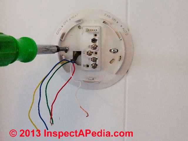
- The string in a typical recently manufactured multiple element thermostat wire is there to help an installer more easily strip off the main outer jacket without harming or nicking the individual inner wire jackets.
Once an installer has used a knife or wire stripper to expose enough of this string to be able to grab onto it with his fingers, he can then pull the string at right angles to the thermostat wire, then slicing easily a little further through the main outer jacket without having to risk any further harm to the new just freshly exposed jackets of the smaller inner wires.
An installer can then simply prune away any of the smaller wires which he may have had to nick before he was able to grab onto the string and to use it to safely strip off the outer jacket. - It's always best to wrap a spare or unused wire around the main thermostat wire outer jacket where the outer wire jacket just starts, so that such wires, if needed, could still be used at a later time or date. C
utting such wires back instead of merely wrapping them back out of the way, may be regretted later on in the job in hindsight. We don't leave bare wire ends because we don't want to risk accidentally shorting out something inside the thermostat or other control device. - Heat-anticipators are typically chiefly found in mechanical (non-digital) thermostats, though some new digital / programmable room thermostats like the 3M-22, discussed
at THERMOSTAT SWITCHES, INTERNAL, provide a nearly identical function referred to as an adjustable thermostat swing-rate (cycle rate or thermostat sensitivity).
Whenever installing or servicing a thermostat with a heat-anticipator, the amperage setting on the heat-anticipator should always be verified as matching the amperage draw on the gas valve or relay that it controls.
See HEAT ANTICIPATOR Adjustment
and HEAT ANTICIPATOR SET & TEST by AMMETER
Not all heating systems and buildings benefit from a heat exchanger but in some cases you want a thermostat with this feature.
See DO I NEED A THERMOSTAT WITH A HEAT ANTICIPATOR? for details.
In any event, if a heat anticipator is included in a thermostat it should be set properly. Otherwise the relay or thermostat may not function properly, resulting in too-short burner on-time (higher heating costs) or room temperature overshoot (wasted heating dollars).
- Color codes for 24V thermostat wires are divided into two groups: - we give a summary tables of both traditional and current thermostat wire color code keys above
- The 5 universal base colors for thermostat wires which are, in order of frequency of use, red, white, green, yellow, and black. These colors are used as follows:
- i. R = Red for the common hot side of the heating transformer may connect to R, RH, RC
- ii. W = White for the switched heating control circuit. Connect to W or W2 (Aux Heat)
- iii. G = Green for the switched main blower control circuit. Connect to G
- iv. Y = Yellow for the switched compressor compressor control circuit. Connect to Y
- v. Black for the other common side of a transformer so that a digital thermostat would not be entirely battery dependent. Connect to C (Transformer)
Whenever installing or servicing a digital thermostat, If possible, it's always best to try and make sure that this wire is properly attached.
- The 5 additional colors for thermostat wires which are generally used for two stage heating and cooling, heat pumps, emergency heat, and other things are usually only found and used in some of the more complex systems. These colors are
- Orange: Heat pump, connect to O.
- Blue: Dark Blue, heat pump, Connect to B (may use orange to O instead)
- pink,
- purple.
- brown - often connects to C or common or to W2 (2nd stage backup heat)
Watch out: while there are some things that these color wires are more commonly used for than others, not all manufacturers agree on which of these additional colors should always be used for what.
- The 5 universal base colors for thermostat wires which are, in order of frequency of use, red, white, green, yellow, and black. These colors are used as follows:
- Other Wire Colors: Gray wire: may be Aux emergency heat, mayu connect to E.
- The temperature actuated on off switch in a thermostat is actually a single pole double throw switch which will have either the heating or the cooling side closed at all times.
- Whenever using a digital thermostat, always use one that has the ability to accept batteries, and also, if possible, try to provide non-battery powering to the thermostat via the thermostat's 'C terminal' connection.
Any digital thermostat (including name-brand thermostats) that does not have the ability to accept batteries, or which does not have it's 'C terminal' properly connected through to a transformer, can cause problems such as requiring frequent battery changes, or possibly may not even work at all in certain types of applications! - Any thermostat wire splices that may be required should always be made in fully visible and accessible locations.
Hiding such splices in a wall or other difficult spot is only inviting trouble later on, for either yourself or for another service person. Instead, just use a longer fresh wire in order to avoid having to leave such a splice in a difficult or hidden place. - A properly wired typical hot water boiler (that does not have a domestic hot water heater exchanger attached) should always be wired such that it will automatically completely shut down all circulators and burners during the warmer periods of the year.
In the past, many of these boilers have been wired to run continuously, even throughout the summer. Such wiring configurations are an extremely costly and inefficient waste of natural gas and/or other natural-energy-resource.
Note: While disabling the LO/DIFF on an aquastat that controls a heating boiler that does not include a tankless coil, we do not necessarily agree that a boiler should always be wired to shut down in summer; details of this approach and the tradeoffs are found
at OPTIMAL LO/DIFF SETTINGS SAVE FUEL - Ed.
- Thanks to reader " Helpful Pointers" Regarding 24V T, 10/7/2012
Old Timer Tips on Shorting Out Thermostat Wires on Purpose to Identify Which Wire is Which
Tips for figuring out which thermostat wires do what: how to identify (R) (W) (B) wires. These tips are from the 1949 Honey Heating Control Handbook [copy on file] for figuring out the function of thermostat wires whose color cannot be determined (for LOW VOLTAGE series 10 type circuits).
Watch out: DANGER OF DEATH BY ELECTROCUTION: don't try this experiment if your thermostat uses line voltage (120V). The procedure Honeywell described was ONLY for low voltage (nominally 25V) equipment.
Watch out also about shorting thermostat wires together on newer HVAC equipment using circuit boards. That advice is only for old, simple series 10 type control circuits. As we report in the article above, on some modern heating and air conditioning equipment shorting wires can blow a circuit board component or fuse. If you've already made this mistake, check for a blown fuse on a circuit board in your furnace or boiler controls.
- With the three thermostat wires properly connected at the heating equipment end (we hope you didn't disconnect them there as well) where they operate a relay or valve, hold the three bare wires together. The heater should run.
- Now remove one of the wires. If the burner stops, this is the (W) or white wire. Attach this wire to the W terminal of the thermostat.
- If the burner does not stop, hold all 3 wires together again and try another wire until the white wire is found.
- After the white wire (W) has been identified and labeled and secured to the (W) terminal, one of the remaining two wires will start the burner when shorted to the white (W). The one that causes the burner to start is the blue (B) wire. Connect it to the (B) terminal.
- The remaining wire is the red wire and should be connected to the (R) terminal.
Shorting Out Thermostat Wires by Accident - Leads to Loss of Heat
Watch Out: do not short any wires together. Turn off power & confirm it is off. Don't forget to turn off all electrical power involved with your heating system before working on thermostat wiring, and confirm that power is off where you are working by using an appropriate test instrument such as a VOM.
Shorting thermostat wires to ground or together is likely to damage components in the thermostat itself or in other heating system components, as this reader's report below illustrates:
I had a no heat situation since replacing my programmable thermostat. I did some checks that the thermostat company said and the thermostat is good. But now my furnace won't come on at all. I can hear the transformer humming. It is a Miller model #M3RL-080-ABW in a four year old manufactured home.
Apparently I touched two live wires together when doing the thermostat installation. I know, I should have turned off the breaker, (power), before working. That is the lesson of the week for sure!
I blew a small purple, two prong, auto style fuse in the electrical board on my furnace. What I did not know is the fuse was marked with a "E" instead of a number, but it is a 4 amp fuse, found at your local automotive store. I was without heat all weekend, even though it could have been on Friday evening.
I'm glad I pulled the fuse and looked to see the metal inside was broken. Otherwise I might have been without heat until I could get a HVAC guy to come out to my house. -- S.R.
Note: your fuse marked with an "E" was probably being read upside down and was a 3-amp fuse. Using a fuse one amp greater incapacity is probably not too dangerous, but it's best not to overfuse as doing so risks equipment damage. Certainly a larger fuse is asking for wiring or device burn-up should a future short circuit occur. - Ed. & reader comments
Since shorting thermostat wires can damage a circuit but can also blow the low voltage transformer, also
see LOW VOLTAGE TRANSFORMER TEST
Reader Question: possible shorted thermostat wires
Our furnace thermostat failed after an adjacent water heater installation. I noticed that wires were pinched between the water heater and the gas pipe. After I loosened the safety straps and freed the wire, the thermostat works. (I reset the furnace). Were squished wires the cause of a temporary short and will the wires keep working if they are undisturbed? - Larry 8/2/11
Reply: check for shorted wires and for thermostat transformer damage as well as for blown fuse
Yes it's surely possible that your thermostat wires were shorted.
Now a short in those wires sometimes lets you off the hook with no trouble, since the wires and thermostat are basically an "on-off" switch that calls for heat (or no heat).
But a thermostat wire short at the transformer could burn out the low voltage transformer that powers the thermostat and heating controls or maybe even damage the thermostat itself.
Find and check the low voltage transformer (often it's mounted near your furnace, on an electrical junction box, or it may be integral in your heater control unit).
See LOW VOLTAGE TRANSFORMER TEST
Question: reader comments on shorting out thermostat wires & fusing requirements
Greetings, not sure if anyone saw this or not, but whoever S.R. is above in the description about shorting out wires seems to maybe have missed the fact that the "E" they refer to is actually a "3" amp fuse and not a 4 amp fuse.
My HVAC installer of 30 years who recently installed 2 furnaces for us and is installing my heat pump agrees that it is a 3 amp fuse. We purchased an extra one just in case. Putting a 4 amp in there may not be good for the board as it may allow too much current for a relay or something and you may fry a piece on the board which is most likely not cheap. I hope this helps - D.M. - 3/12/12
Reply:
Thanks D.M., We posted your important fuse size comment right in the article
at SHORTING OUT THERMOSTAT WIRES - Leads to Loss of Heat.
...
Reader Comments, Questions & Answers About The Article Above
Below you will find questions and answers previously posted on this page at its page bottom reader comment box.
Reader Q&A - also see RECOMMENDED ARTICLES & FAQs
On 2021-03-24 by (mod) - Where does the black wire go?
@Veronica, in the article above please take a look at the very first thermostat wire color code table titled
Basic Thermostat Terminal Wiring Color Codes
On 2021-03-23 by Veronica
Where does the black wire go?
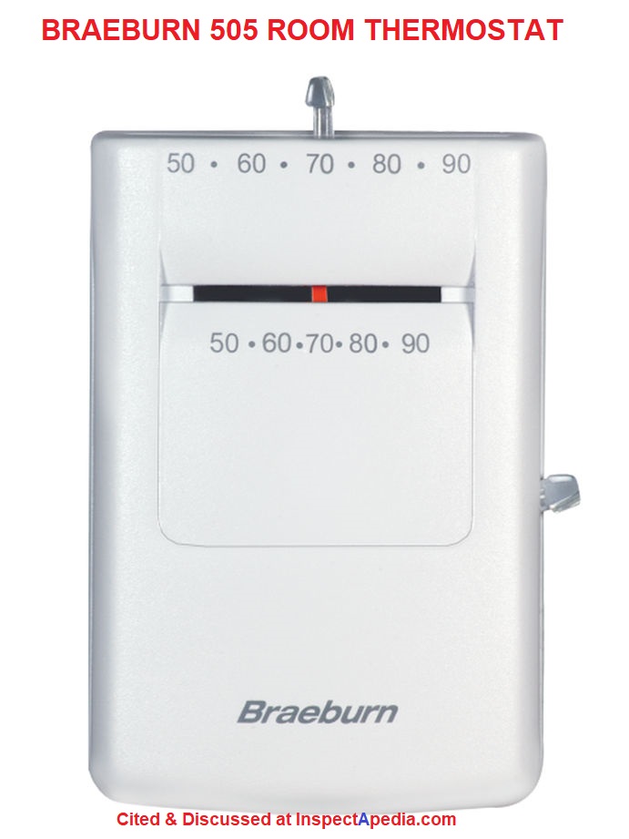
On 2021-01-03 by (mod) - Braeburn 505 "Heat only" thermostat
 Victoria
A Braeburn 505 "Heat only" thermostat will work fine for you and is very inexpensive.
On 2021-01-03 11:48:38.064047 by Victoria
I see red/white/blue&white.
I need to find a thermostat to operate steam heat only. No AC or Fan while using these wires.
Wiring from 60s, radiator is cast iron, new boiler.
The Braeburn Megaswitch was installed to replace old round Honeywell. Now no longer sets, ( coil retracts back to center and heat is coming from all radiators)
I purchased new non programmable heat only round Honeywell w/o anticipator but has on/off switch in back
Did not work
The wires - what type of brand thermostat can I use.
Reader Question: Where does the white wire go?
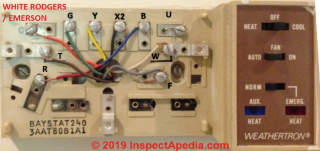
On a York roof mount heat and air system thermostat wire white go to the com terminal or the white terminal - Gary
Reply:
Not sure for your system which wire goes to which terminal - take a look at the wiring instructions on the appliance or in the installation manual to be sure. If you give me the product name and model number we can help find the installation and wiring instructions for a certain answer.
I didn't find a customer service telephone number for York but the company's website includes consumer help and is found at http://www.york.com.
Another reader offered: on a York roof mount heat and air system thermostat wire white goes to the com terminal or the white terminal
...
Continue reading at THERMOSTAT INSTALLATION STEPS or select a topic from the closely-related articles below, or see the complete ARTICLE INDEX.
Or see THERMOSTAT WIRING TIPS & COLOR CODES FAQs - questions & answers about TT wiring posted originally at the end of this page.
Or see these
Recommended Articles
- THERMOSTAT INSTALLATION STEPS
- THERMOSTAT WIRE CONNECTIONS
- COMMON WIRE at THERMOSTATS
- CONVERT LINE to LOW VOLTAGE THERMOSTAT
- LINE VOLTAGE THERMOSTATS
- THERMOSTAT WIRE CONNECTIONS - 2-WIRE like the T87F
- THERMOSTAT WIRE CONNECTIONS - 3-WIRE Red, White, Blue Wires
- THERMOSTAT WIRE CONNECTIONS - 4-WIRE Red, Yellow, Green, White
- THERMOSTAT WIRE CONNECTIONS - 5-WIRE Blue/Black, Red, White, Yellow, Green
- THERMOSTAT WIRE CONNECTIONS - 6-WIRE Red, White, Blue, Yellow, Green, Orange Wires
- THERMOSTAT WIRE CONNECTIONS - 8-WIRE Black, Red, White, Yellow, Green, Orange, Brown, Blue
- THERMOSTAT WIRE SORTING to ID R W
- THERMOSTAT WIRING AZEL i-LINK
- THERMOSTAT WIRING 3M-22 FILTRETE
- THERMOSTAT WIRING AMERICAN STANDARD
- THERMOSTAT WIRING ARGO
- THERMOSTAT WIRING CHROMOLOX
- THERMOSTAT WIRING ELECTRIC HEAT
- THERMOSTAT WIRING EMERSON
- THERMOSTAT WIRING FLAIR INSTRUCTIONS
- THERMOSTAT WIRING GENERIC Control Points
- THERMOSTAT WIRING GOODMAN
- THERMOSTAT WIRING HONEYWELL
- THERMOSTAT WIRING LINE VOLTAGE 120-208-240VAC
- THERMOSTAT WIRING NEST
- THERMOSTAT WIRING TRANE HVAC
- THERMOSTAT WIRING WHITE RODGERS
- THERMOSTAT WIRE TERMINAL ID CODES / FUNCTIONS
- THERMOSTAT WIRING OPENING SEAL
- THERMOSTAT WIRING COLOR CODES
Suggested citation for this web page
THERMOSTAT WIRING COLOR CODES at InspectApedia.com - online encyclopedia of building & environmental inspection, testing, diagnosis, repair, & problem prevention advice.
Or see this
INDEX to RELATED ARTICLES: ARTICLE INDEX to HVAC THERMOSTATS
Or use the SEARCH BOX found below to Ask a Question or Search InspectApedia
Ask a Question or Search InspectApedia
Try the search box just below, or if you prefer, post a question or comment in the Comments box below and we will respond promptly.
Search the InspectApedia website
Note: appearance of your Comment below may be delayed: if your comment contains an image, photograph, web link, or text that looks to the software as if it might be a web link, your posting will appear after it has been approved by a moderator. Apologies for the delay.
Only one image can be added per comment but you can post as many comments, and therefore images, as you like.
You will not receive a notification when a response to your question has been posted.
Please bookmark this page to make it easy for you to check back for our response.
IF above you see "Comment Form is loading comments..." then COMMENT BOX - countable.ca / bawkbox.com IS NOT WORKING.
In any case you are welcome to send an email directly to us at InspectApedia.com at editor@inspectApedia.com
We'll reply to you directly. Please help us help you by noting, in your email, the URL of the InspectApedia page where you wanted to comment.
Citations & References
In addition to any citations in the article above, a full list is available on request.
- [1] ...
- [2] Thanks to reader S.R. for discussing loss of heat due to a thermostat wiring mistake, October 2010
- [3] Thank to Mr. Scott Meenen , G&S Mechanical Services , for providing some common thermostat wiring codes also found at Mr. Meenen's web page Malware Deleted 12/9/2014 . Mr. Meenan provides heating, heat pump, and air conditioning repair services in Maryland, Washington D.C., and northern Virginia. He can be contacted at 301-591-1646 or by Email to Malware Deleted 12/9/2014 - 10/2010. Quoting:
We service American Standard, Amana, Arco, Arco-Air, Bryant, Carrier, Coleman Evcon, Comfortmaker, Day/Night/Payne, Dunham-Bush, Fedders, Fredrich, Goodman, General Electric, Heil, Intertherm, ICP, Janitrol, Lennox (Armstrong, Johnson Air-Ease), Miller, Modine, Nordyne, Rheem/Ruud/Weatherking, Sears, Stewart Warner, Trane, Weather King, Williams, White-Westinghouse, Whirlpool, Weil Mclain, York, (Frasier Johnson/Borg Warner) and others. - [4] Azel Technologies Inc., P.O. Box 53138 10 Royal Orchard Blvd. Thornhill, Ontario, Canada L3T 7R9 Ph: 905-223-5567 Fax: 905-223-3778 Email: info@azeltec.com, Website: www.azeltec.com.
- [5] Honeywell Controls, the company wants you to use their contact form at this web page: http://www51.honeywell.com/honeywell/contact-support/contact-us.html
Honeywell Consumer Products, 39 Old Ridgebury Road Danbury, CT 06810-5110 - (203) 830-7800
World Headquarters, Honeywell International Inc., 101 Columbia Road, Morristown, NJ 07962, Phone: (973) 455-2000, Fax: (973) 455-4807 1-800-328-5111- Honeywell product model numbers & instruction Manuals: see http://yourhome.honeywell.com/home/Applications/FindYourModelNumber.aspx
- [6] White Rodgers Thermostats and HVAC controls,
Homeowner information: http://www.emersonclimate.com/en-US/brands/white_rodgers/Pages/wr-homeowner-info.aspx
Contractor information: http://www.emersonclimate.com/en-US/brands/white_rodgers/wr_contractor_info/Pages/white-rodgers-contractor-info.aspx
White Rodgers Product Catalog (don't misspell the company's name as White Rogers Thermostats) -
http://www.emersonclimate.com/Documents/thermostats.pdf - Thermostat Catalog - [7] White Rodgers 1F90 Low Voltage Digital Comfort-Set thermostat Installation Instructions, PN 37-3654, White-Rodgers Division, Emerson Electric Co., 9797 Reavis Rd., St. Louis MO 63123
- [8] "Automatic Oil Burner Controls - Thermostats", Domestic and Commercial Oil Burners, 3rd Ed., Charles H. Burkhardt, McGraw Hill, 1969 (and later editions), ASIN B0000EG4Y8
- [9] Thermostat wiring color codes & conventions, Thanks to reader " Helpful Pointers" Regarding 24V T, 10/7/2012
- [10] Domestic Central Heating Wiring Systems and Controls, 2d Ed., Raymond Ward, Newnes, ISBN-10: 0750664363, ISBN-13: 978-0750664363, Quoting from Amazon.com:
This unique A-Z guide to central heating wiring systems provides a comprehensive reference manual for hundreds of items of heating and control equipment, making it an indispensable handbook for electricians and installers across the country. The book provides comprehensive coverage of wiring and technical specifications, and now includes increased coverage of combination boilers, recently developed control features and SEDBUK (Seasonal Efficiency of Domestic Boilers in the UK) boilers ratings, where known.
In addition to providing concise details of nearly 500 different boilers fuelled by electric, gas, oil and solid fuel, and over 400 programmers and time switches, this invaluable resource also features numerous easy-to-understand wiring diagrams with notes on all definitive systems. Brief component descriptions are provided, along with updated contact and website details for most major manufacturers. - [11] Proliphix Corporate Headquarters [Website: proliphix.com] , 3 LAN Drive Suite #100, Westford, MA 01886 Phone: +1.978.692.3375 Toll Free (U.S.): 866-IP-LIVING (866.475.4846) Fax: +1.978.692.3378 - Sales: sales@proliphix.com Marketing: marketing@proliphix.com Customer support: support@proliphix.com http://www.proliphix.com/ - quoting from the company's website:
All Proliphix Network Thermostats come with our free Uniphy Remote Management Service. This unique offering lets you monitor and control your HVAC systems by simply pointing your Browser to our secure Proliphix Web Site. Enjoy the convenience of programming a thermostat from any location, using a simple graphical interface. No computer equipment or software is required. And since Proliphix takes care of the network configuration for you, you’ll be up and running in no time. We’ll even proactively monitor your thermostats and send you an immediate email or SMS message when an HVAC problem is detected. - [12] "Heating Control Handbook for the Installer and Service Man,Oil Burner, Gas Burner and Stoker Controls", Honeywell Corporation, March 1949 [copy on file as HoneywellControlsHandbookSA1399-2-1949.pdf] . Some of the controls discussed in detail here include the
- Honeywell T1 and T11A = Series 10
- Honeywell T21A (T2) = Series 20
- Honeywell T847A = Series 80
- Honeywell RA117A (RA1) = Series 10
- Honeywell LA101A = Series 10,
- Honeywell LA419A (LA4) = Series 40
- V155A = Series 10, V435A = Series 40, V575A = Series 50, V835A = Series 80
- [13] Trane TCONT800 Series Touch Screen Programmable Comfort Control Ownes Guide, American Standard, Inc., Troup Highway, Tyler TX 75711, January 2005, Telephone: Customer Service: 1-877-3381, website: www.trane.com
- In addition to citations & references found in this article, see the research citations given at the end of the related articles found at our suggested
CONTINUE READING or RECOMMENDED ARTICLES. - Our recommended books about building & mechanical systems design, inspection, problem diagnosis, and repair, and about indoor environment and IAQ testing, diagnosis, and cleanup are at the InspectAPedia Bookstore. Also see our Book Reviews - InspectAPedia.
CONTINUE READING or RECOMMENDED ARTICLES.
- Carson, Dunlop & Associates Ltd., 120 Carlton Street Suite 407, Toronto ON M5A 4K2. Tel: (416) 964-9415 1-800-268-7070 Email: info@carsondunlop.com. Alan Carson is a past president of ASHI, the American Society of Home Inspectors.
Thanks to Alan Carson and Bob Dunlop, for permission for InspectAPedia to use text excerpts from The HOME REFERENCE BOOK - the Encyclopedia of Homes and to use illustrations from The ILLUSTRATED HOME .
Carson Dunlop Associates provides extensive home inspection education and report writing material. In gratitude we provide links to tsome Carson Dunlop Associates products and services.
 | HOME | ABOUT | ASK a QUESTION | CONTACT | CONTENT USE POLICY | DESCRIPTION | POLICIES | PRIVACY | |
| © 2025 - 1985 Publisher InspectApedia.com - Daniel Friedman | |||||||||