 Chimney Reserve Draft
Definition & measurement of excess or "draft reserve" at chimneys & flues
- POST a QUESTION or COMMENT about chimney draft & the barometric damper or draft regulator
How to measure chimney reserve draft at heating equipment or at chimneys.
This article series explains the methods of measurement and proper adjustment settings for draft regulators or barometric dampers on oil fired heating equipment. This article series answers most questions about central heating system troubleshooting, inspection, diagnosis, and repairs.
InspectAPedia tolerates no conflicts of interest. We have no relationship with advertisers, products, or services discussed at this website.
- Daniel Friedman, Publisher/Editor/Author - See WHO ARE WE?
Definition & Measurement of Chimney Reserve Draft Dr
On 2020-11-11 by Thomas Maucione - I want a chart for measuring reserve draft
Chart for measuring reserve draft ?
[Click to enlarge any image]
Moderator reply:
Thomas
Thank you for an interesting question about reserve draft at heating appliance chimneys.
I don't think a chimney reserve draft chart quite fits the topic but I can describe a simple method for getting at the question of how much reserve draft capacity a chimney has.
Various sources cite the importance of having some reserve draft - that is more draft capacity than the minimum required by the appliances vented into a chimney - but finding a chart or procedure that specifies the amount of required reserve draft or even a procedure for calculating it (I'm doubtful that it's measurable) are as scarce as hen's teeth.
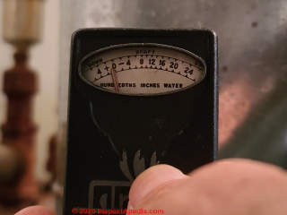
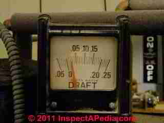
Photo: using the Bachrach Draft-Rite, a small portable draft measurement device, to measure chimney draft and chimney reserve draft, as described below.
Definition of chimney reserve draft
Reserve chimney draft is the amount of additional updraft or exhaust draft capacity of a chimney beyond the amount of draft that is needed and has been set to properly vent the devices that are connected into it.
Example: if we set an oil fired heating boiler draft in the breech (shown above) to -0.05" of water (updraft), the manufacturer's recommended draft level, then using the procedure given below we can measure the additional draft of which the chimney is capable, beyond 0.5". If by closing the barometric damper on the boiler the draft increases to -0.08" of water (updraft) then the chimney reserve draft or Dr = (0.8 - 0.5) = -0.03" of water. .
Besides a recommended draft setting chart provided by Beckett and given and cited below, I'm looking for some reserve-draft guidelines to add here, but meanwhile I have to emphasize that no simple or single "reserve draft" answer can possibly be correct.
How to Measure Chimney Reserve Draft
 For oil fired heating equipment it's trivially easy to make a crude measurement of reserve draft as we will describe here.
Normally at oil and at some gas fired heating equipment we measure draft at two locations: over the fire or in the combustion chamber where typically for oil fired heating equipment we may see -0.02 to -0.03 inches of water column pressure, and in the breech or at the stack pipe (properly, the flue vent connector) measured just a few inches above the boiler or furnace top, and preferably 6" or more before the barometric damper itself we will find around -0.05 inches of water column.
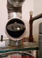
Above: a draft regulator or barometric damper installed on the Peerless oil-fired heating boiler used in this reserve draft measurement example. [For its photo-op we tipped this damper door open more-widely than its normal position when the boiler is running.]
- Inspect the chimney draft controls:
First confirm that the oil fired heating appliance has a barometric damper or draft regulator installed.
If it doesn't it's not a proper installation. Second confirm that the oil fired heating appliance is either the only heater vented into the chimney or that other appliances venting into the chimney have their own draft regulator that can be temporarily stopped as we will describe. - Run the heating equipment up to full temperature:
Next, with the barometric damper properly adjusted and the oil fired heating equipment's draft properly set, let the heating equipment run until it's up to full operating temperature - about 5 minutes or longer.
Tip: to keep the boiler running during the two draft measurements described below you may need to set the room thermostats up as high as they'll go - or the service tech might need to jump the TT terminals on the boiler's control board, and you'll want to start this process when the boiler has been off for a time to be sure that it won't reach its HI LIMIT and shut itself off before you've finished measuring reserve draft.
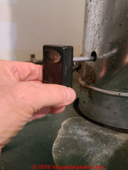
- Prepare the draft measurement device: as shown above, depending on the device used, you may need to "zero" your draft measurement tool.
Above: I'm in the process of zeroing the draft measuring tool.
We are using the Bachrach Draft-Rite handy, portable, and not highly-precise draft gauge that must be held horizontal and zeroed (by holding a finger over an opening on the back of the device and rotating the device until the pointer is at zero) before obtaining the actual chimney / breech draft measurement.
In my photo above the needle isn't exactly on zero because, frankly, it was darn hard to hold the Draft-Rite and my camera perfectly correctly at the same time. Other draft measuring devices are more precise and are not position sensitive.
Details about how to use this particular draft gauge are at
BACHRACH DRAFT-RITE DRAFT GAUGE PROCEDURE
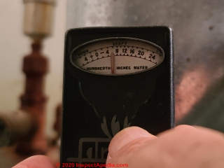
Below: after zeroing the draft gauge, and with the boiler up to operating temperature and running continuously, we're measuring -0.05" of water draft - the proper setting for this heater.
- Measure operating draft Do as previously adjusted:
Now measure the draft in the breech - above the heater and before the draft regulator.
Once you've got the Draft-rite tool properly positioned and zeroed, lift the blocking finger and, without moving the tool, read the draft on the gauge.
At this measurement notice the position of the the hinged door on the barometric damper. It should be at least partly open - thus allowing air to enter the chimney and thus preventing excessive draft at the heating appliance.
This boiler had been cleaned and adjusted by the heating oil service company (Bottini Fuel, Poughkeepsie, NY) just a few days before we took these photos of draft measurement.
So we're seeing the draft just where we'd expect it to be and where the service tech put it, at 0.05" H2O.
Watch out: if under normal operation your oil fired heating appliance barometric damper door is fully closed then we already know that the draft at that chimney is limited and that the reserve draft is probably zero.
Provided that the barometric damper door or flapper is partly open, admitting additional air into the flue above the appliance, we know that there is at least some reserve draft in the chimney.
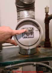
Below: holding the barometric damper door shut to make a crude measurement of chimney reserve draft.
- Temporarily close the barometric damper completely.
As shown above I've pushed the damper door fully shut.
- Measure the increase in draft with barometric damper fully closed:
Now, with the heating appliance still running, manually hold the barometric damper door fully closed, and measure the draft again.
You should see an increase in the draft measured on your draft gauge.
Really? Well not exactly. You might not see much change in draft measurement when closing the damper door.
Why? Possibly because the amount of reserve draft at this heater is very small and also because just holding the barometric damper flapper shut does not completely close off air intake into the chimney at the damper. In order for the barometric damper's door to move freely it does not fit air-tight in its opening. Some air leakage will continue around the damper door.
You could try a more precise measurement of the chimney draft reserve by temporarily sealing the whole barometric damper opening (some use aluminum foil) but in our OPINION that added draft will be so small that it's probably within the error of this whole procedure, because of seasonal and other causes of variation in any draft measurement. Below we list examples of causes of variation in chimney draft measurements.
- Calculate Dr chimney reserve draft: Subtract from the larger draft measured at step 4 the initial (presumably smaller) draft measured at step 3. The result is the chimney reserve draft at the time your measurements were taken.
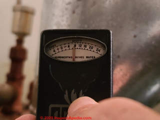
On our Bachrach draft gauge we see the draft increased from -0.05" water to just under 0.08" of water - which is encouraging, meaning that our chimney venting system is not operating at maximum capacity and that it might handle variations in weather and other conditions.
That Dr = 0.03" increase in draft is a crude estimate of the reserve draft at that chimney and heating appliance.
Watch out: For gas fired heating appliances measuring reserve draft is both difficult and unsafe, because doing so, using the primitive reserve draft measurement procedure described above, would require blocking off the fixed, open makeup air openings at the gas fired appliance draft hood, and because fooling around with draft on gas fired appliance could risks production of dangerous, even fatal carbon monoxide gas.
Examples of Variables in Chimney Draft & Reserve Draft
There are many chimney draft variables including at least these:
- Chimney materials, type, height, where the higher the chimney the greater the draft once draft has been established, but also the greater resistance to starting draft when the chimney is cold
- Chimney-vented appliance fuels: oil vs. gas, where gas fired appliances generally run cooler so produce less draft and are at greater risk of carbon monoxide hazards.
The weight of the gases or combustion products vented into the chimney varies, but can be expressed in weight per unit volume - Chimney temperatures: temperature rage over which appliances operate
The higher the heating appliance operating temperature the hotter its exhaust and so the hotter the gases produced and the greater the draft produced in the chimney - Chimney environment, temperature, wind, barometric pressure and how those can possibly vary over the course of year - variations in heating season
The colder it is outside the building and around the chimney the colder is the outside air; the colder the outside air the heavier it is, making it more-difficult to initiate draft in a cold chimney, but providing stronger draft once the chimney and its vented gases are sufficiently warmed. - Chimney use: number and type of devices vented into the flue and how they are producing heat and draft
Chimney use simultaneity: conditions under which multiple appliances vented into a single flue may be on or off simultaneously - Chimney draft interferences in draft such as lack of combustion air or damage to a chimney or even something as simple as an open chimney cleanout door
See details at CHIMNEY CLEANOUT DOOR - Combustion air availability: adequate combustion air must be provided or not only will combustion be improper and potentially unsafe, but draft will also be reduced
- Chimney draft interferences such as a chimney that is not above the ridge or is too close to the rooftop, a chimney top without a proper cap, air leaks anywhere in the flue, blockages anywhere in the chimney flue, and of course blockages in the heating equipment itself such as a soot-clogged heat exchanger.
Watch out: the bottom line is that when a chimney draft is inadequate the heating system can become very unsafe, leading to a puffback explosion where oil fired equipment is involved to fatal carbon monoxide poisoning where gas fueled appliances are involved.
As the simplest example, excerpting from this MIT source:
The reduced average temperature of the gases, together with milder weather, results in reduced theoretical draft and may lead to spillage problems, especially if the chimney is designed with little reserve draft capacity. (Steel 1981)
In part that's why heating appliances use a draft hood (gas appliances) or a barometric damper or draft regulator (wood and oil fired appliances) so that the installer can always build a chimney with excess or reserve draft capacity while regulating draft at the appliance to be sure that it is not excessive.
Most documents discussing chimney reserve draft are written for gas fueled heating equipment, perhaps because of the CO hazard. Other resources are listed below.
Watch out: setting excessive draft at any heating appliance means you are sending excess heat up the chimney rather than into the building, thus increasing building heating or energy costs.
See details at CHIMNEY DRAFT & PERFORMANCE
Recommended Oil Fueled Appliance Chimney Draft Settings
This table is adapted from Beckett's data cited just below. These are NOT reserve draft measurements, they are basic draft measurements, in the breech, for oil fired heating equipment.
Oil Burner Draft Setting 1 |
|||
| Season / Condition | Outdoor Temp °F | Chimney Temp °F 2 | Draft, H2O3 |
| Winter start-up | 20 | 110 | 0.050 |
| Winter Operation | 20 | 400 | 0.136 |
| Fall start-up | 20 | 80 | 0.011 |
| Fall Operation | 20 | 400 | 0.112 |
Notes to the table above & Research on Chimney Draft Reserve
- Beckett, COMBUSTION AIR REQUIREMENTS for OIL BURNERS [PDF] - R.W. Beckett Corporation, retrieved 2020/11/15 original source: https://www.beckettcorp.com/support/tech-bulletins/combustion-air-requirements-for-oil-burners/ source of data in the table above
Excerpt: Measure the CO2 or O2 in the flue gas at the trace of smoke level. Then open the air adjustment to add reserve air until the CO2 is lowered by at least 1.5% (or the O2 is raised by at least 2%).
Oil burner adjustment instructions address "reserve air" settings that in turn may affect draft, such as this from Beckett in the discussion of an outside air intake system (for combustion air) - Chimney temperature is being measured at the same location as draft measurement. Beckett is giving 400 degF as the normal and desired operating temperature for an oil burner once it has reached stable operating conditions; typically we need to run the oil burner for 5 minutes or longer to reach this point.
- Draft measurements expressed in inches of water column, measured in the breech, above the boiler or furnace but below or before the draft regulator or barometric damper.
Watch out: when setting draft by measuring draft in the breech it is important to also measure draft over the fire. Over fire draft should be less than in-the-breech draft, around 0.1 - 0.2" H2O, otherwise you may be causing backpressure in the combustion chamber, a condition that can damage the heater and / or the oil burner. Below Beckett elaborates on this point.
See details
at DRAFT MEASUREMENT, CHIMNEYS & FLUES - how to measure draft
Also see DRAFT REGULATOR, DAMPER, BOOSTER for help in how to adjust the chimney draft - BACHRACH DRAFT RITE INSTRUCTIONS [PDF] [From our archives], Bachrach Corporation has offices world wide.
Bachrach Canada: Bacharach, Inc. 10 West Pearce Street, Unit 4 Richmond Hill, Ontario. L4B 1B6, Canada Toll Free: +1 (800) 328 5217 Email: support@bachcan.ca
Bachrach Europe: Bacharach, Inc. Unit D12 & D13 Santry Business Park, Swords Road Santry, Dublin, Ireland Telephone: +353 (1) 284 6388 Email: eutechnical@mybacharach.com eusales@mybacharach.com
Bachrach USA: Bacharach, Inc. 621 Hunt Valley Circle New Kensington, PA 15068, United States Toll Free: +1 (800) 736 4666 Email: help@mybacharach.com
[Request for technical review sent 2020/11/17] - Beckett, UNDERSTANDING DRAFT [PDF] R.W. Beckett Corporation, retrieved 2020/11/15 original source: https://www.beckettcorp.com/support/tech-bulletins/understanding-draft/
Excerpt:
Because there is little draft during a cold start-up, you cannot depend on the additional combustion air caused by draft.
Watch out: Be sure the burner does not depend on this air by setting the burner for smoke-free combustion with a low over-fire draft (.01 to .02 inches of water). A burner must produce good smoke-free combustion under low draft conditions.
Watch out: Using a high draft setting to obtain enough combustion air for clean burning can cause trouble. A burner which produces clean combustion only with high draft may cause smoke and soot any time the chimney is not producing high draft. - Tjerlund, TJERLUND DRAFT REGULATORS [PDF]
- Prapas, Jason, TOWARD THE UNDERSTANDING AND OPTIMIZATION OF CHIMNEYS FORBUOYANTLY DRIVEN BIOMASS STOVES [PDF] (2013) Dissertation, Colorado State University, Dept. of Mechanical Engineering, retrieved 2020/11/15 original source: https://mountainscholar.org/bitstream/handle /10217/80968/ Prapas_colostate_0053A_12021.pdf;sequence=1
- Buckley, Jim, CHIMNEY DRAFT [PDF] Buckley Rumford Co.
1035 Monroe Street
Port Townsend, WA 98368
360 385 9974, cell 360 531 1081
email: buckley@rumford.com retrieved 2020/11/15 original source: https://www.rumford.com/draft.html
Excerpt:
The important thing for us is to note that draft is directly proportional to the height of the chimney, the temperature of the flue gasses and the atmospheric pressure.
A twenty foot tall chimney creates a pressure differential twice as great as a ten foot chimney.
A chimney at sea level where a = 14.7 pounds per sq.ft. has almost one and a half times the pressure differential as an equal chimney at 10,000 feet in elevation where a - 10 pounds per sq.ft. - Kershaw, John B.C., F.I.C., "The Theory and Practice of Steam Generation", Part III - the Steam-Raising Plant, in Technics, Volume 3 ( January to June 1905), pp. 503-512, George Newnes Ltd., London.
Excerpt: As regards the draft required within the furnace of a boiler, in order to obtainproper combustion of the fuel, Hiller, in his handbook on the Working of Steam Boilers, states that high efficiency can be obtained with 0.30 inch behind the bridge, and 0.45 inch in the main flue at the back of the boiler; but it is better to have some reserve of draft power, and to be able to produce, when desired, 0.50 inch in the furnaces and 0.65 or 0.70 inch in the main flue. - Op. Cit. p. 505 - PERFORMANCE STANDARDS AND OTHER ENGINEERING CRITERIA FOR FOSSIL FUEL BURNING BOILERS & WATER HEATERS [PDF] New York, Department of Environmental Protection, retrieved 2020/11/15 original source: https://www1.nyc.gov/assets/dep/downloads/pdf/air/engineering-criteria-fossil-fuel-burning-boilers-water-heaters.pdf
Full title: Department of Environmental Protection Promulgation of Revised Chapter 2 of Title 15 Of the Rules of the City of New York Concerning Performance Standards and Other Engineering Criteria For Fossil Fuel Burning Boilers & Water Heaters - Steel, F, "CBD-217. DOMESTIC CHIMNEYS AND GAS VENTS [PDF] 1981), National Research Council Canada / Conseil national de recherches Canada retrieved 2020/11/15 original source: web.mit.edu/parmstr/Public/NRCan/CanBldgDigests/cbd217_e.html
...
Continue reading at DRAFT MEASUREMENT, CHIMNEYS & FLUES - topic home, or select a topic from the closely-related articles below, or see the complete ARTICLE INDEX.
Or see these
Recommended Articles
- CHIMNEY DRAFT & PERFORMANCE
- CHIMNEY HEIGHT & CLEARANCE CODE required height of a chimney above the building roof.
- CHIMNEY HEIGHT EXTENSIONS
- CHIMNEY INSPECTION DIAGNOSIS REPAIR - home
- CHIMNEY RESERVE DRAFT MEASUREMENT
- DIRECT VENTS / SIDE WALL VENTS
- DAMPERS & DRAFT REGULATOR TYPES
- DRAFT REGULATORS / HOODS GAS HEATERS
- DRAFT INDUCER FANS
- DRAFT MEASUREMENT, CHIMNEYS & FLUES
- DRAFT REGULATOR, DAMPER, BOOSTER
- DRAFT REGULATOR SOOT INSPECTION
- GAS PRESSURES LP vs NATURAL GAS
- GAS PRESSURE vs BUILDING HEIGHT
- WATER PRESSURE MEASUREMENT and in that article DEFINE WATER PRESSURE per FOOT of HEIGHT
Suggested citation for this web page
CHIMNEY RESERVE DRAFT MEASUREMENT at InspectApedia.com - online encyclopedia of building & environmental inspection, testing, diagnosis, repair, & problem prevention advice.
Or see this
INDEX to RELATED ARTICLES: ARTICLE INDEX to HEATING SYSTEMS
Or use the SEARCH BOX found below to Ask a Question or Search InspectApedia
Or see
INDEX to RELATED ARTICLES: ARTICLE INDEX to CHIMNEYS & FLUES
Or use the SEARCH BOX found below to Ask a Question or Search InspectApedia
Ask a Question or Search InspectApedia
Try the search box just below, or if you prefer, post a question or comment in the Comments box below and we will respond promptly.
Search the InspectApedia website
Note: appearance of your Comment below may be delayed: if your comment contains an image, photograph, web link, or text that looks to the software as if it might be a web link, your posting will appear after it has been approved by a moderator. Apologies for the delay.
Only one image can be added per comment but you can post as many comments, and therefore images, as you like.
You will not receive a notification when a response to your question has been posted.
Please bookmark this page to make it easy for you to check back for our response.
IF above you see "Comment Form is loading comments..." then COMMENT BOX - countable.ca / bawkbox.com IS NOT WORKING.
In any case you are welcome to send an email directly to us at InspectApedia.com at editor@inspectApedia.com
We'll reply to you directly. Please help us help you by noting, in your email, the URL of the InspectApedia page where you wanted to comment.
Citations & References
In addition to any citations in the article above, a full list is available on request.
- [1] "Instructions for Installing FIELD Type AF Barometric Draft Controls," Form No. 31 DC 30666, Field Corporation, Mendota, IL 61342, web search 04/02/2011, original source: http://www.fieldcontrols.com/pdfs/04592700.pdf, Field Controls, Kingston, North Carolina 28501, Tel: 919-522-3031
- [2] Tjernlund Draft Controls, A Series (single action for oil, solid fuel, and fan-assisted gas burners) and B Series (double action for gas heating appliances), web search 04/02/1011, original source: http://www.tjernlund.com/Tjernlund_8500490.pdf , Tjernlund Products, Inc., 1601 Ninth Street, White Bear Lake MN 55110-6794, Tel: 651-426-2993 or 800-255-4208 website: www.tjernlund.com Email: fanmail@tjfans.com
- Our recommended books about building & mechanical systems design, inspection, problem diagnosis, and repair, and about indoor environment and IAQ testing, diagnosis, and cleanup are at the InspectAPedia Bookstore. Also see our Book Reviews - InspectAPedia.
- In addition to citations & references found in this article, see the research citations given at the end of the related articles found at our suggested
CONTINUE READING or RECOMMENDED ARTICLES.
- Carson, Dunlop & Associates Ltd., 120 Carlton Street Suite 407, Toronto ON M5A 4K2. Tel: (416) 964-9415 1-800-268-7070 Email: info@carsondunlop.com. Alan Carson is a past president of ASHI, the American Society of Home Inspectors.
Thanks to Alan Carson and Bob Dunlop, for permission for InspectAPedia to use text excerpts from The HOME REFERENCE BOOK - the Encyclopedia of Homes and to use illustrations from The ILLUSTRATED HOME .
Carson Dunlop Associates provides extensive home inspection education and report writing material. In gratitude we provide links to tsome Carson Dunlop Associates products and services.


