 Well Pump Tailpipes & Low Water Cutoffs
- POST a QUESTION or COMMENT about the function of well tailpieces or tailpipes to protect from low well flow rates
Well tailpieces for well pump protection:
Well Tailpipes or Tailpieces serve as Low Water Protection Devices.
This article describes the use of a tailpipe or tail piece, or other low water cutoff controls to protect a well pump from damage in a low-recovery rate well, thus extending the life expectancy of water pumps and pump controls.
InspectAPedia tolerates no conflicts of interest. We have no relationship with advertisers, products, or services discussed at this website.
- Daniel Friedman, Publisher/Editor/Author - See WHO ARE WE?
What are the Best Low Water Cutoff Devices for Well Pump Protection?
 How do we protect the well pump from damage if the well is subject to seasonal or permanent low flow rates or has a poor recovery rate?
Here we explain the function & role of a tailpiece installed at the bottom of well piping in order to protect the pump and other water supply equipment controls from damage.
[Click to enlarge any image]
Discussed here are several devices or methods used to protect a water pump from damage due to loss of well water or running the pump "dry":
- WELL PIPING TAILPIECE LOW WATER PROTECTION
- LOW WATER CUTOFF for WELL
- WATER PRESSURE REGULATION for LOW FLOW WELLS - Smart Tank™
- WATER PUMP CAVITATION EXPLAINED
- WATER PUMP PROTECTION SWITCH - separate article
Low Well Water well pipe tailpieces or well tailpipes to protect the well pump
When the well pump's capacity is known to exceed the flow rate of the well, a tail pipe, tail piece, or low water cutoff control is installed to protect the pump from damage such as that caused by well pump cavitation or motor overheating.
Details: some wells that are known to have intermittent low water problems may be equipped with a special tailpiece on the water pick-up end of the well pipe precisely to prevent the well pump from becoming damaged when water level in the well drops too low.
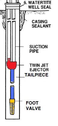
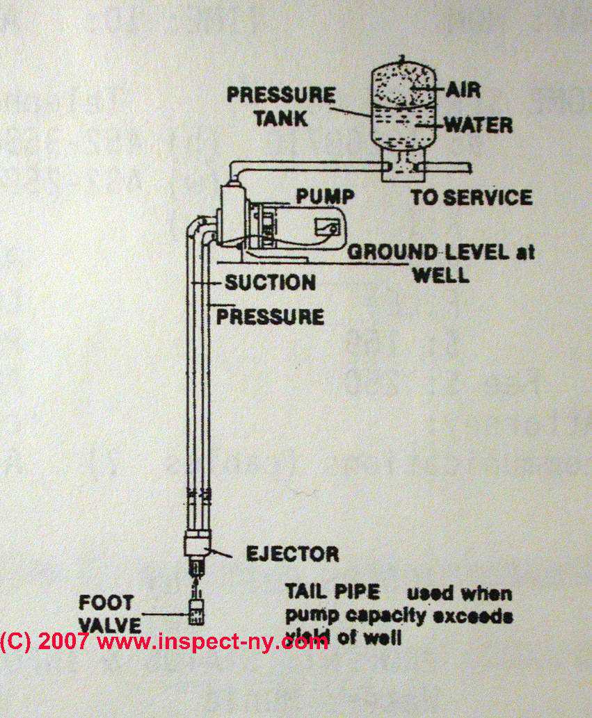
The red component in our sketch (left) is the ejector used by a two-line jet pump to bring water from the bottom of the well. This red component shows where a well flow protection tailpiece may be added - as an extension below.
A longer taipiece (blue in our sketch) extending into well water (30 inches recommended by the Alberta Canadia DOA) may help avoid air intrusion, but in addition, a special fitting at the in-water end of the tailpiece can cause water to recirculate through a well pump if well water level becomes too low.
If the well pump is a submersible model (recommended for well depths over 80 feet), a similar low well water protection device may be installed in the well. In our sketch at left the foot valve is shown in yellow.
The well piping tailpiece (also shown in this SKETCH) permits the in-well water pump to continue to run by recirculating well water within the pump but by halting delivery of water or slowing delivery of water to the building.
2 Line Jet Pump Piping Tailpiece Recommendations
Well pump manufacturers generally recommend
- 2 Line Jet Pump Pipe Sizes:
1 1/4" suction pipe or larger
1" drive water pipe.
[Click to enlarge any illustration]
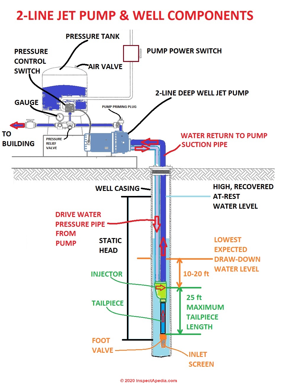
Our drawing, showing the main parts of a 2-line jet pump and well installation is adapted from the
Lancaster JET PUMP INSTALLATION MANUAL [PDF] cited in detail atReferences or Citations
Watch out: When the pump is located a long distance from points of
water use, it may be necessary to increase the discharge
pipe size in order to reduce pressure loss. (Franklin VersaJet Pump Manual 2022)
- Maximum Tailpiece Length below the Injector of a 2 line Jet Pump
Minimum length = none. In some wells the foot valve may be immediately below the injector.
Maximum length = 25 ft. below the bottom of the ejector to which the tailpiece is attached. |
This places the tailpiece depth at 35 ft. to 45 ft. below the lowest anticipated drawdown level of water in the well.
Note that this is a "typical" 2-line jet pump tailpiece maximum length.
Some installation instructions like those from Franklin Water's VersaJet permit the tailpiece to extend 34 ft. below the injector assembly.
- Injector depth:
10 to 20 feet below the lowest anticipated draw-down water level in the well.
Really? Some manufacturers or well installers may permit installing the ejector itself above the lowest anticipated draw down water level. But keep in mind that the ejector cannot lift water more than about 25 ft. - Check valves:
1 or more check valves, including a foot valve at the bottom of well piping, are usually needed to avoid loss of prime and to keep your pump working.
The number and location of check valves recommended by the manufacturer will depend on well depth and pump capacity.
See details at WELL PIPING CHECK VALVES
2-Line Jet Pump Tailpiece References
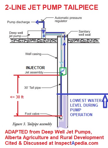
- Canada, Alberta, DEEP WELL JET PUMPS [PDF] Alberta Agriculture and Rural Development, Alberta Ag-Info Centre
Call toll-free: 310-FARM (3276)
Website:www.agriculture.ablerta.ca - retrieved 2022/09/05 original source: https://www1.agric.gov.ab.ca/
Excerpt: Jet pumps will lose their prime if the water level in the well drops below the foot valve.
This result can be prevented in a slow yielding well by using an automatic pressure regulator and a weak well tailpipe below the injector (Figure 3). [Shown above, with annotations by InspectApedia.com ]
This tailpipe system will automatically adjust the pumping rate to the well capacity.
Watch out: The mechanical seal on the pump shaft is water lubricated and water cooled, so the pump should never be run without the pump casing being filled with water.
Electrical Low Water Cutoff Devices to Protect the Well Pump
Many sources, including the Penn State School of Forest Resources recommend installing a low water cutoff device to protect a well pump that has to operate in an inadequate or low-yield well. That resource describes an electrical low-water cutoff switch:
Normally, a low-water cut-off switch
controlled by water-level sensors in the well should
be connected to a relay at the pump switch box.
A low-water signal relayed to the main switch should override other pump controls and stop the pump if the water level drops to a critically low point where air or sediment would be pulled into the system.
A low water sensing device to protect a well pump may be installed in an intermediate water storage tank, for example.
A different approach to water pump protection where the well yield is poor is a tailpiece that is installed in the well itself.
When the water level inside a well drops too low, the tailpiece re circulates water through the well pump (keeping the pump cool and protecting it from damage) until the well has recovered and the water level has risen.
Watch out: the low water cutoff devices that we discuss here are intended for building water supply piping to prevent well pump damage. These low water cutoff devices or switches are distinct from and have nothing to do with the heating or steam boiler low water cutoff safety devices discussed
Water Pressure Regulation to Protect the Well Pump: Flexcon SmartTank™
A still different approach that may provide some water pump protection by reducing the well pump cycling rate is the installation of a Smart Tank™ that regulates water flow in the building. According to the manufacturer, Flexcon Industries,
Every Smart Tank system includes a relief valve and a manifold that provides ports for the system’s pressure switch, pressure gauge, drain valve and relief valve.The Smart Tank pressure system works just like a standard pressure tank system but with one major difference - consistent water pressure delivery!
1.On demand, water is drawn from the Online pressure tank until the cut-in pressure of the switch turns the pump on.
2.System water now flows through the regulating body of the Smart Tee valve. The valve will maintain constant water pressure at each given flow rate, and consistent water pressure over a broad range of flows.
3.When system demand ends, the Smart Tee’s calibrated bypass port keeps the pump running just long enough to fill the tank and satisfy the cut-out setting of the pressure switch. The pump shuts off, and the system is now ready for the next demand.
The Smart Tank pressure system will reduce pump cycles by as much as 75%, and give the homeowner the benefit of constant water pressure. Fewer pump starts and longer run times means longer pump and tank life.
Well Pump Cavitation Damage
Well pump cavitation describes the entry of air or gases into the mechanical parts that are trying to move water through a water pump. The presence of air or other gases in the actual pump chambers or around the water pump impellers leads to overheating of these parts and mechanical damage to the pump moving parts.
Cavitation can also cause the pump to have to work longer to satisfy the water demand and thus its electric motor to overheat, also reducing motor life.
Cavitation inside of a water pump can be caused by several problems including:
- Inadequate well yield: if the yield of a well drops for any reason, trying to pump water beyond the safe yield of a well pump can introduce air into the well pump and water piping.
See WELL YIELD DEFINITION where we define safe well yield and discuss the importance of a proper match of the well pump capacity and its output rate to the well's safe yield. In that article you will
find how to WELL YIELD, SAFE LIMITS
Also see AIR DISCHARGE at FAUCETS, FIXTURES - Oversized pumps that mis-match the well flow rate to the pump's output rate can also cause the pump to form a strong vacuum inside the pumping chamber around the pump impeller.
The vacuum, in turn, causes dissolved gases in the water itself to leave solution and return to bubble form.
...
Reader Comments, Questions & Answers About The Article Above
Below you will find questions and answers previously posted on this page at its page bottom reader comment box.
Reader Q&A - also see RECOMMENDED ARTICLES & FAQs
 Question: can I move the injector close to the pump?
2020/05/14 Dennis
Can the ejector go closer to pump?
Moderator reply: how does the 2 pipe well system injector get water up to the building?
Dennis:
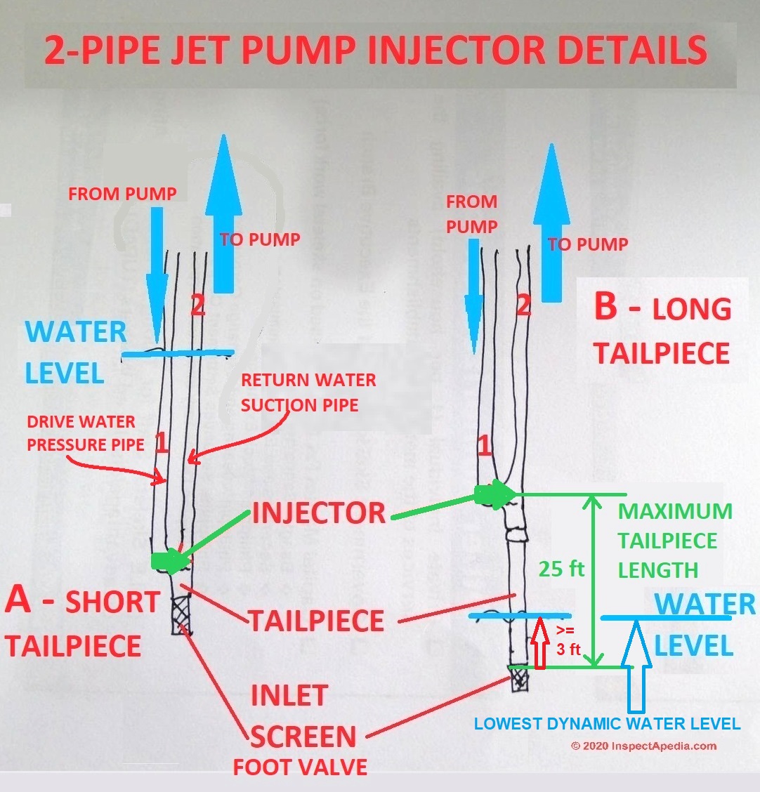
The ejector in a 2 line jet pump needs to quite close to or even below the surface of the water (varying by manufacturer specs, in the well, though you'll see in our ejector tailpiece illustration here, in some installations the ejector and tail piece do not have to be at the very bottom of the well piping.
So the amount by which you can move the 2-line jet pump injector up towards the pump itself is limited by
- the lowest dynamic water level in the well (place the foot valve at least 3 ft. below the lowest dynamic water level)
- the specific pump manufacturer's specifications for maximum tailpiece length (25' to 34' depending on pump specifications)
To be clear about how your 2 line jet pump is working to deliver water to the building:
In the building or somewhere above ground a 2 line jet pump includes an impeller that pushes water down the smaller-diameter well pipe and near the bottom of that pipe, in the well, water is pushed through a jet or venturi - an opening shaped like a funnel.
The venturi, by reducing the opening size in a funnel shape, increases the speed of water passing through the venturi - also called the "injector".
That increase in water creates a suction that draws additional water up through the tailpiece, into the injector, and the combined volume of water sent down the pipe plus additional water sent up the larger pipe back to the pump is what actually delivers water into the building.
The maximum recommended length of the 2 line jet pump well piping tailpiece is usually 25 feet.
Why 25 ft. for the maximum tailpiece length?
It's no coincidence. The lift force generated by a venturi is capable of drawing water up in any application is about 25 ft.
So the deep well 2 line jetpump tailpiece length limitation of 25 ft. derives from the same limitation that tells us that a shallow well 1 line jet pump can not lift water from a depth of more than 25 ft.
The difference is that a 1 line jet pump's venturi is above ground, while the 2 line jet pump's venturi or injector is down in the well.
The additional "lift" capacity of the 2 line jet pump comes from the added force or "push" generated by that smaller-diameter pipe that is pushing water down the well piping as well as pushing it back up the well piping to the surface.
Otherwise it can't generate the required lift.
 On 2018-04-09 by (mod) - pump won't build pressure
Aaron,
I suspect that priming is incomplete OR there's a lack of water in the well OR there's an air leak in the piping connections.
Seee WATER PUMP WONT STOP RUNNING for detailed diagnostic and repair steps.
On 2018-04-09 by Aaron
I have a 50 foot well. Replaced 1 pipe jet pump, foot valve and pipes, which now is a whole new system. Primed but will not build up pressure. What could be the problem?
On 2017-08-22 by (mod) - I think I have a clogged venturi jet
That's an interesting idea, and one I'd try myself, but talking to someone about a system I know nothing about I'm a little more cautious: new pump? Did you keep the instructions? If so there'll be a tech support telephone to call at the manufacturer. Give them a call.
I'm doubtful that backwashing will actually fix a clogged jet anyway. You're blowing whatever it is back right into the area where it got picked-up in the first place.
(There are approaches using chemicals to try to clear a clogged point screen in a driven point well but those do not work and should not be tried on a well bore - you could contaminate the well. )
You may need to pull the well piping. That's nowhere near the pump as I surmise you're using a 2 line jet pump in a deep well.
On 2017-08-17 by Todd Whipps
I think I have a clogged venturi jet, is it safe to reverse the pump in order to try and back flush the jet? I just replaced the pump with a new one and I'm nervous I may damage it.
On 2017-04-29 by (mod) - I am am wanting to pull the water line to install a new foot valve.
Sounds like a 2 line jet pump; there is probably a connector under the cap that connects to the well piping (or a compression fitting around piping; you'll need a tripod and winch if there's any weight.
On 2017-04-29 0 by Ashok
Hello Sir,
After digging about 2 feet, I have located a 2" well head in my back yard. There are 2, 1" pipes going to the pump. There is a triangle shaped bracket below the head held by 3 bolts. I took the bolts off. The bracket dropped to the ground.
Not sure if the head is screwed down or it just sits on the casing. I think since the bracket dropped then the head just sits on the casing.. I am am wanting to pull the water line to install a new foot valve. This well is about since the 1950s. please advice.
Thanks,
Ashok
On 2017-04-18 by Dan - 2" jet packer 46.5' deep well with static water level at 38'
I have 2" jet packer 46.5' deep well with static water level at 38'. I pulled out the 1-1/4" drop pipe to find there was no strainer after the check valve at the bottom of the drop pipe. Does that mean the strainer/ screen is on the bottom of the 2" casing pipe".
If so could I add a section of 1-14" pipe above the check valve and a 1-14" sand point after the check valve and drive it through the strainer/ screen on the end of the 2" casing and into the soil while leaving the leathers/ jet packer at the same depth as they were originally?
Of course using all new pipe, packer, check valve, couplers .etc. I had a problem losing prime if the well was not used for a few days and when it was used it seemed to run low on water after a few toilet flushes (the leather packing was not sealing in the casing). I thought pounding a point down further in the casing would help me get deeper into water. Any ideas or comments appreciated.
On 2016-11-13 by (mod) -
I figure in any application a fluttering foot valve is likely to speed to failure. But before replacing it I'd want to have a diagnosis, lest I simply run through a box of foot valves to no avail.
On 2016-11-13 by JOE
In my septic pump chamber..I just extended my piping 7 feet, added 2 elbows, a union quick release and a new foot valve (spring loaded check valve with screen). I now hear the foot valve 'chattering' or fluttering (cycling open and closed) when the effluent pump is on.
The tank empties without any issues is just 15 miknutes, keeps pressure, pump is still primed. Question, Should I be worried about the fluttering foot valve ???
On 2016-03-21 by (mod) - don't confuse a water supply pump with septic system pumps
Joe
This sounds as if there is either a leak in well piping or the foot valve is not working.
But this article is about water supply well piping.
You want to review
and
On 2016-03-21 by stormyjoe@att.net
I have a deep well jet pump , my piping is is 100 feet into the well , i pulled all the pipe and replaced the foot valve and replaced the pump also ,
upon attempting to reprime the pump i have tried filling the pipe in the well back to the pump to no avail, what should have only been about 40 gallon of water to fill i have poured over 70 gallon into and still haven't came back upto the pump yet ,
is it possible for the tail piece that i did not bother to change is just letting all the water that I'm putting in just flow back into the well preventing me from priming the well
On 2015-10-01 by Anonymous
What is the safest way to use dry ice to open up perforations clogged from hard water.
Question: 7 GPM is the minimum needed to keep a pump cool and that when it runs out of water it will turn itself off. Is this true?
(May 23, 2011) Sage Hill said:
Our local pump installer is recommending a 7 GPM pump for our 5-6 GPM well (which will likely be less in the summer).
He says that 7 GPM is the minimum needed to keep a pump cool and that when it runs out of water it will turn itself off. Is this true? I thought it was best not to let the well run dry.
Reply:
You are quite correct that a water pump pump should not be allowed to run dry, it's likely to damage its bearings and lead to a need for pump replacement.
There may be a switch that actually turns off the well pump under low well water conditions but more common is a tailpiece that cycles water through the pump to keep it from overheating and simultaneously reduces or stops sending water up into the building.
Unless such a pump protector is installed, no the pump is not protected. That protection can be electrical or by a tailpiece.
See WATER PUMP PROTECTION SWITCH
Question: suspect well piping ejector may be causing the pump to not reach its shutoff pressure
(Oct 22, 2012) Ted Platt said:
40 year old ejector on this deep (100 ft.), system, with a foot valve. Rebuilt pump, changed sediment filter but suspect that the jet in the ejector may be the problem. Pump unable to reach the 45 lb shut off pressure even when running for an hour or more.
I reduced the shut off pressure to 35 lbs. now to temporally resove this problem. The pump holds the prime, the slight taste of sand in the water is also a concern. perhaps a now submerged parts in sediment?
Reply:
I would look for dirt or debris in the pump impeller assembly first. If the well screen were partly clogged you'd slow the input into the piping and pump system but you'd not limit the pressure achievable by the pump.
Question: How does the tailpipe prevent the ejector from drawing down the water level in the well casing far enough to admit air into the foot valve?
(June 13, 2014) Anonymous said:
A jet pump tailpipe question. How does the tailpipe prevent the ejector from drawing down the water level in the well casing far enough to admit air into the foot valve?
Is the suction efficiency of the ejector venturi low enough that it can pull up from below itself only a small height of water column into the tailpipe so that the foot valve is always submerged?
If so how would one evaluate the suction capability of a given ejector assembly to determine the minimum length of the tailpipe needed to balance the suction?
I have a fairly shallow (40 ft) well with a low recharge rate (1 ½ - 2 gpm) that I can easily overpump with the smallest available jet pump
. I don’t want to sacrifice too much of the depth and capacity of the casing so that I can avoid short cycling - a minimum length of tailpipe would be desired.
Reply:
Anon,
The tailpiece is designed to recirculate water through the submersible pump rather than letting all of the water volume pushed by the pump flow up the pipe and into the building it serves. By recirculating water through the pump we prevent damage from pump cavitation (circulating air or air and water).
Yes a foot valve is normally always submerged, well below the top of water in a properly-functioning well.
The tailpiece is installed above the foot valve - see our sketches above.
Should water level fall abnormally low for any reason air or a mix of air and water can enter the well piping through the foot valve. But the introduction of that air should cause the tailpiece to recycle water rather than sending air up the well piping system.
In the case you describe, you might want to check out the wide range of well pump short cycling protection devices now on the market. These devices, typically electrical controls, take a different approach to well pump protection, monitoring current draw to detect when air is entering the well pump.
Those devices are discussed separately
at WATER PUMP PROTECTION SWITCH
...
Continue reading at WATER PUMP PROTECTION SWITCH or select a topic from the closely-related articles below, or see the complete ARTICLE INDEX.
Or see these
Recommended Articles
- AIR DISCHARGE at FAUCETS, FIXTURES
- SHORT CYCLING WATER PUMP
- WATER PRESSURE PROBLEM DIAGNOSIS TABLE
- WATER PUMP DIAGNOSTIC TABLE
- WATER PUMP PROTECTION SWITCH
- WATER PUMP WONT STOP RUNNING
- WELL PIPING CHECK VALVES
- WELL PUMP PRIMING PROCEDURE if you need to re-prime your jet pump.
- WELL CAPS & COVERS - requirements for sealed well caps & covers, requirements for vents & exclusion of vent requirements for some jet pump installations.
- WELL PIPING TAIL PIECE
Suggested citation for this web page
WELL PIPING TAIL PIECE at InspectApedia.com - online encyclopedia of building & environmental inspection, testing, diagnosis, repair, & problem prevention advice.
Or see this
INDEX to RELATED ARTICLES: ARTICLE INDEX to WATER SUPPLY, PUMPS TANKS WELLS
Or use the SEARCH BOX found below to Ask a Question or Search InspectApedia
Ask a Question or Search InspectApedia
Share this article:Try the search box just below, or if you prefer, post a question or comment in the Comments box below and we will respond promptly.
Search the InspectApedia website
Note: appearance of your Comment below may be delayed: if your comment contains an image, photograph, web link, or text that looks to the software as if it might be a web link, your posting will appear after it has been approved by a moderator. Apologies for the delay.
Only one image can be added per comment but you can post as many comments, and therefore images, as you like.
You will not receive a notification when a response to your question has been posted.
Please bookmark this page to make it easy for you to check back for our response.
IF above you see "Comment Form is loading comments..." then COMMENT BOX - countable.ca / bawkbox.com IS NOT WORKING.
In any case you are welcome to send an email directly to us at InspectApedia.com at editor@inspectApedia.com
We'll reply to you directly. Please help us help you by noting, in your email, the URL of the InspectApedia page where you wanted to comment.
Citations & References
In addition to any citations in the article above, a full list is available on request.
- Franklin Electric FRANKLIN CONVERTIBLE VERSAJET PUMP INSTRUCTIONS [PDF]
- Mark Cramer Inspection Services Mark Cramer, Tampa Florida, Mr. Cramer is a past president of ASHI, the American Society of Home Inspectors and is a Florida home inspector and home inspection educator. Mr. Cramer serves on the ASHI Home Inspection Standards. Contact Mark Cramer at: 727-595-4211 mark@BestTampaInspector.com
- John Cranor [Website: /www.house-whisperer.com ] is an ASHI member and a home inspector (The House Whisperer) is located in Glen Allen, VA 23060. He is also a contributor to InspectApedia.com in several technical areas such as plumbing and appliances (dryer vents). Contact Mr. Cranor at 804-873-8534 or by Email: johncranor@verizon.net
- In addition to citations & references found in this article, see the research citations given at the end of the related articles found at our suggested
CONTINUE READING or RECOMMENDED ARTICLES.
- Carson, Dunlop & Associates Ltd., 120 Carlton Street Suite 407, Toronto ON M5A 4K2. Tel: (416) 964-9415 1-800-268-7070 Email: info@carsondunlop.com. Alan Carson is a past president of ASHI, the American Society of Home Inspectors.
Thanks to Alan Carson and Bob Dunlop, for permission for InspectAPedia to use text excerpts from The HOME REFERENCE BOOK - the Encyclopedia of Homes and to use illustrations from The ILLUSTRATED HOME .
Carson Dunlop Associates provides extensive home inspection education and report writing material. In gratitude we provide links to tsome Carson Dunlop Associates products and services.
 |
HOME | ABOUT | ASK a QUESTION | CONTACT | CONTENT USE POLICY | DESCRIPTION | POLICIES | PRIVACY | |
| © 2026 - 1985 Publisher InspectApedia.com - Daniel Friedman | |||||||||