
InspectAPedia® FREE Encyclopedia of Building & Environmental Construction, Diagnosis, Maintenance & Repair |
Question? Just ask us! InspectAPedia
|
 Above Ground Oil Storage Tank Installation or Replacement
Steps to remove the old & install a new oil tank
- POST a QUESTION or COMMENT about installing oil storage tanks
How to replace an old above ground oil storage tank (AST) by installing a new one to meet most stringent environmental protection guidelines.
In 20 detailed steps, this article illustrates how a licensed and trained team remove an old oil tank and install a new tank that includes an oil leak containment system.
This article series explains how to install, use, & maintain heating oil storage tanks.
InspectAPedia tolerates no conflicts of interest. We have no relationship with advertisers, products, or services discussed at this website.
- Daniel Friedman, Publisher/Editor/Author - See WHO ARE WE?
Oil Tank Replacement: Installing a New Oil Tank
 Proper oil storage tank installation for a long-life and trouble-free oil storage tank use and thus for reliable oil heat service at a building requires that the tank be installed following good industry practices (described in this article) supplemented by proper homeowner and oil heat service technician inspection and maintenance.
Watch out: Although we illustrate the process with some detail here, specialized knowledge and experience are needed.
Oil tank replacement is not a task that a homeowner can nor should attempt. Doing so may result in loss of heat, unsafe heating system, a very costly oil spill, and violation of environmental laws.
Beyond "following the rules" of good oil tank installation, here we illustrate, step by step, the procedure including:
- preparing the oil storage tank for easy access and removal
- installing the new oil tank in an oil leak containment tub
- installing the necessary oil tank fill and vent piping
- oil supply and return piping to the oil burner
- getting the oil burner working properly after a new oil tank has been installed
- final site cleanup after the oil tank installation job is complete
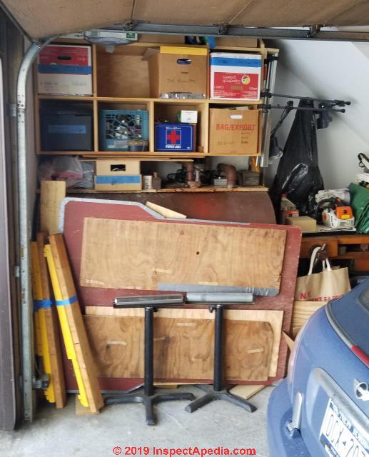
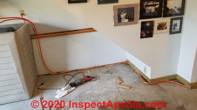
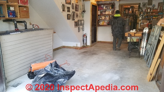
Photo:
clutter around the existing oil tank to be removed should be removed before the oil tank crew show up at the property.
Step 1: Make the Oil Tank Replacement Job Easier for the Installers
That means removing stored items, clutter and debris around and near the oil tank.
As the new oil tank to be stored in the garage at this property was to be placed in a containment tank, we removed surrounding tables and items stored in the area.
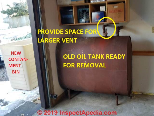
Above: we cut away a portion of the overhead shelving support to be sure that there would be working space to install the new, larger oil tank 2" diameter vent pipe.
Outside you can see the Tankmate™ poly oil storage tank containment "tank tub" or "tank containment bin", a product of Oil Storage Solutions cited below.
Step 2: Prepare the Building to have No Heat
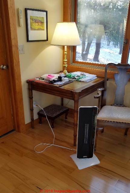
Above: an electric heater used indoors.
Typically it takes 6 hours or more to remove an old above ground oil storage tank and install a new one. During that time your building's oil fired heating equipment will remain shut down.
In very cold weather, both for comfort and to reduce the risk of frozen water pipes, you may want to run the heating system up to a higher than normal indoor temperature for several hours before starting the oil tank replacement job.
You may also want to borrow and turn on a few electric heaters to keep the building occupants more comfortable.
As this oil tank replacement was completed in a garage open to freezing outdoor temperatures, the oil tank installers also used a kerosene-fueled torpedo construction heater both to warm the work area and critically, to heat up their oil transfer pump that otherwise is recalcitrant when it's cold.
Before work proceeds, the oil heating equipment is now turned off.
Step 3: Remove Oil from Old Oil Tank
The existing oil storage tank was nearly full of No. 2 heating oil at the start of this job. Except for seepage at the tank gauge during fill the old oil tank was not leaking when it was replaced.
But the combination of site requirements for oil tank containment systems (due to the home's location), the accumulation of sludge in the tank, and the fact that the oil line supplying the oil fired heating boiler was fed from the bottom of the oil tank (where the sludge and water reside) were reasons to replace the oil tank.
Later in this article you'll see the remarkable amount of debris and sludge we found in this oil tank.
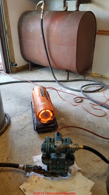
Above: a kerosene-fired torpedo construction heater used to warm the transfer pump. In the background you can see the snorkel and oil line hooked up to remove oil from the oil tank.
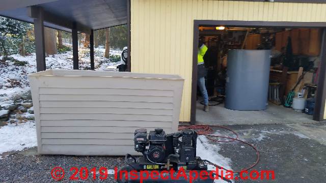
The air compressor used to operate the transfer pump was kept outside the garage as it's a gasoline-operated model - photo above. In our photo showing the compressor in the foreground, behind it you can see the 110% capacity oil tank tub, a containment vessel required for this oil tank installation.
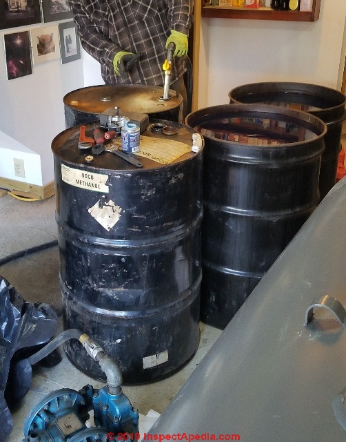
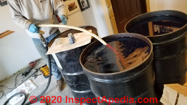
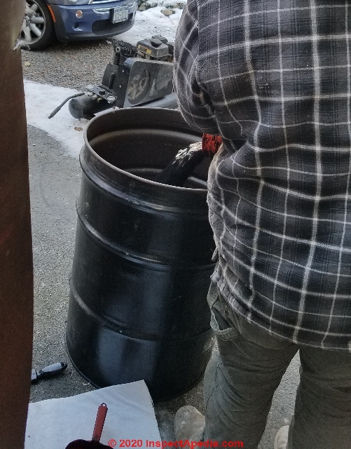
Rather than pay to dispose of nearly an entire tank of recently delivered heating oil, the installers used a compressed-air operated transfer pump to remove most but not all of the oil,
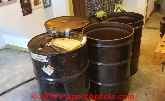
pumping it into temporary storage using 55-gallon steel drums - shown below.
Watch out: The pump's pick-up tube or snorkel (shown below), inserted into the existing oil storage tank, is kept high enough from the tank bottom to avoid picking up water and sludge that were likely to be present in this oil storage tank that we estimated was more than 30 years old.
Step 4: Prepare the New Oil Tank for Installation
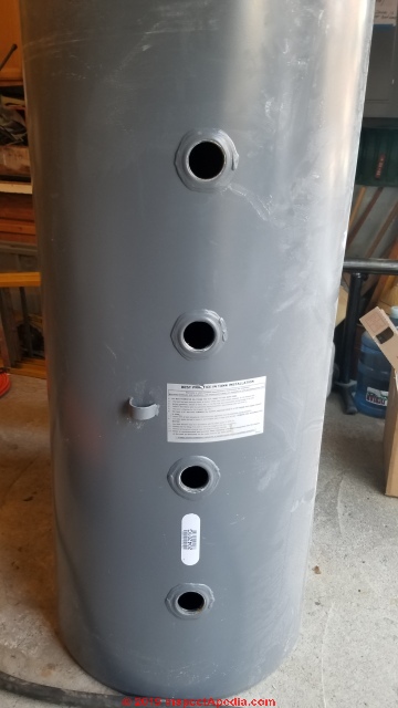
While the existing oil tank is being emptied, the new oil storage tank,
in this case a 275 Gallon steel oil tank produced by Granby, is brought inside and prepared for installation. New oil tank prep includes at least the following:
- Knockouts that are installed in each tapped tank opening are removed
- As the oil lines are to be piped from the top of the new tank, a plug must be installed in the tank's bottom outlet.
- The tank feet are assembled and installed and the tank is first leveled, and then it should be set to slope 1/4" per foot down or away from the bottom outlet, even if that outlet is not to be used.
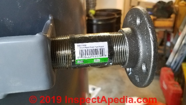
This oil tank is being installed with 4-inch long 2" NPT pipe and bottom flanges to form the tank support feet. The bottom flanges are particularly important to avoid risk that the tank feet cut into or damage the oil tank tub into which this tank will be placed.
- If the oil tank has been stored outside where it might be contaminated with water or ice those would have to be removed.
- The top fittings for the oil tank will be installed after the tank is upright and in position.
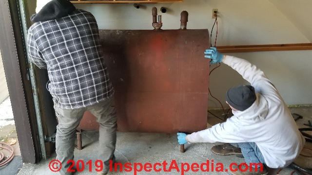
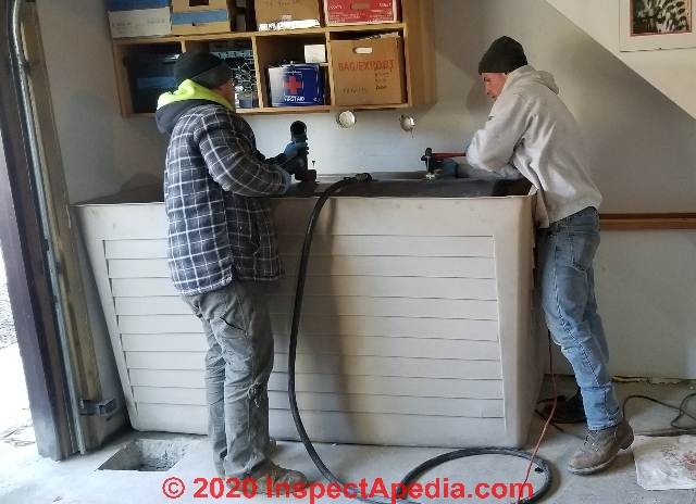
Step 5: Prepare to Remove the Old Oil Tank
While the transfer pump is finishing removing the usable oil from the existing oil storage tank, the technicians prepare the old tank for removal.
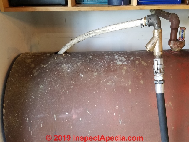
Cut the existing fill and vent pipes to the old oil tank - notice that the operator is running a sawzall with a metal cutting blade kept some distance back from the tank fill and vent ports so that any metal debris from sawing will not fall into and contaminate heating oil that may still be in process of transfer out of the tank.
Close the tank bottom drain valve, tap on it to be sure it's shut, and with considerable caution, loosen and then at the oil tank, remove the existing bottom-feed oil tank line to the oil burner.
Typically the installers will remove the old copper oil line between tank and burner as the old one is likely to be sludge-clogged or damaged; however at this installation, the existing oil line to the burner was just a few years old so we decided to retain it as part of the new two-line oil piping to the burner that we'll install later in this process.
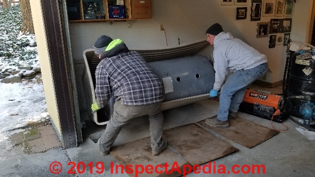
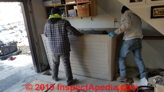
Step 6: Complete Heating Oil Transfer & Remove Old Oil Tank
The tank installer checks the status of the heating oil being transferred, again, taking care not to pump water or sludge into the temporary oil storage drums as that oil is going to be moved into the new oil tank when it's ready.
With the oil transfer pump stopped and the snorkel removed from the oil tank, the technicians pull the oil tank away from the wall and tip it up to carry it out of the building.
With the existing tank nearly empty except for its reservoir of sludge, the tank can be tipped on end and carried outside.
Step 7: Prepare to Install Oil Tank Protective Bollards
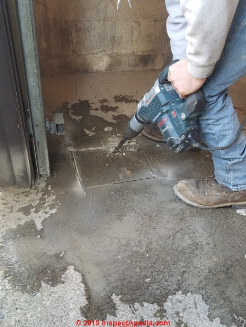
Though in our OPINION this requirement is inconsistently applied and not always fully rational, in general, if an oil storage tank (or heating equipment itself) is located in a garage where it might be struck by a vehicle, local or state code officials may require that the oil tank or equipment be protected by one or more bollards - concrete-filled steel posts set into concrete.
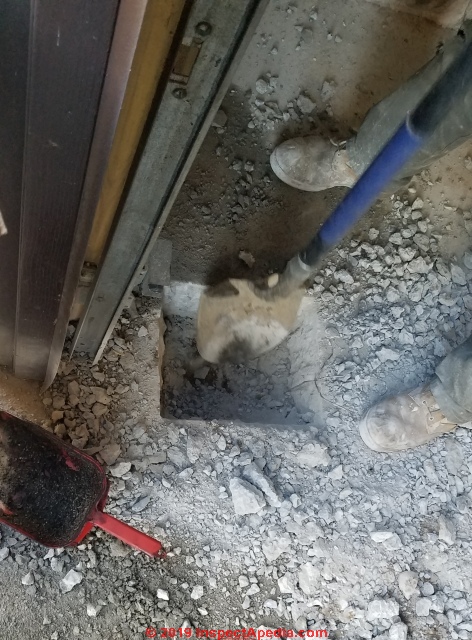
Here the local code official, whose opinion and advice are the final legal authority, wanted a baluster to protect the new oil tank from being struck by a vehicle that might impact the garage wall from outside. In our opinion this was an event so unlikely as to be near impossible, but we follow the local code official's guidance.
The installers cut an appropriate hole through the concrete floor slab in the garage to permit a later installation of the bollard, as once the oil tank and containment tub are in place it would be difficult to make that opening.
Really? Ironically just a few days after this oil tank installation, we learned of a nearby catastrophe at another home nearby: a neighbor, working on their car, left it with emergency brake off and in neutral; the car rolled down a long sloping driveway, crossed a residential street, continued to make a modest turn, rolled now at speed down the driveway of a nearby home, and smashed into the home's garage and door, knocking down and breaking through a concrete block foundation wall!
Humbled, we have officially dropped griping about the bollard requirement to protect oil storage tanks.
Details are at PROTECTION BOLLARDS for MECHANICAL EQUIPMENT
Step 8: Place the New Oil Storage Tank in Position
The installers slide the footed and bottom-plugged and leveled oil tank into the oil tank containment tub, using heavy cardboard upon which to lay the tank so as not to gouge the heck out of it when sliding it across the concrete floor into the tub.
Then the tub-with-oil-tank is tipped upright and moved into position.
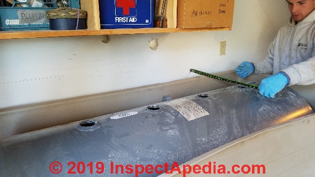
The installers measure distances from the building walls to square-up the tank in position, and slide the tank left or right to align appropriate tank top tappings with the existing oil tank fill and vent openings.
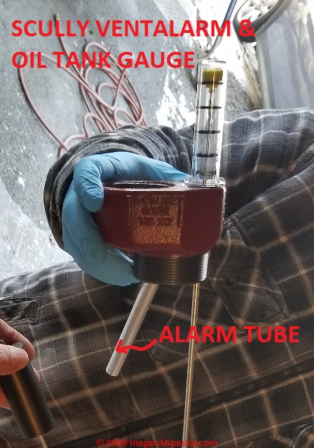
Step 9: Install the New Oil Tank Gauge, Alarm, Fill & Vent Pipes
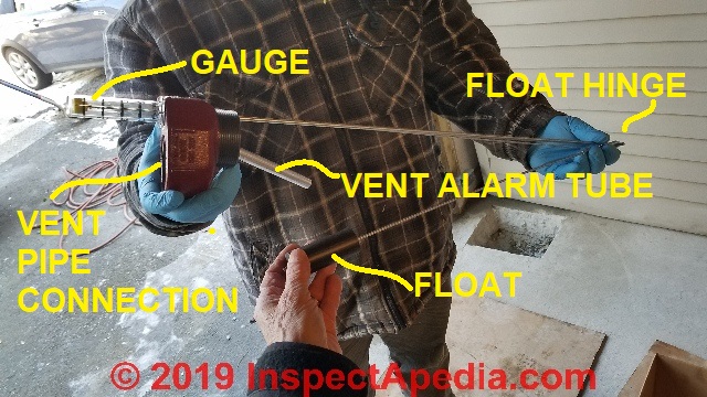
Above: the Scully Ventalarm™ and Oil Tank Gauge (Scully Signal Co.) ready for installation. The old guy's hand (mine) in the lower portion of the photo is holding the gauge float. Notice that the float and gauge rods are hinged.
That silver tube hanging down from the red cast-iron Scully gauge assembly is the actual oil tank whistle or alarm that will go quiet when, as oil reaches the bottom of the tube, air stops exiting the tank through the whistle body.
With the oil tank upright and in position, and if necessary, with larger hole(s) drilled through the building wall to pass the full 2" diameter fill and vent pipes to the building exterior, the installers are ready to fit the Scully™ combination oil tank gauge and Vent Alarm into the oil tank top vent tapping.
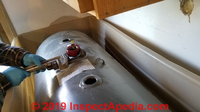
Oil Tank Gauge & Vent Alarm Installation Tip
As you prepare to insert the oil tank gauge assembly into the oil tank top tapping, pull up the oil tank gauge indicator to the "full" position and hold it or use a small ViseGrip™ pliers to hold the gauge in that position. That will cause the gauge rod arms to bend to the most closed position - similar to the photo of the gauge we showed just above.
With the oil tank gauge rods folded to the "closed" position, you avoid bending, damaging, or fouling the gauge as it is inserted into and screwed down onto the oil tank top tapping.
The risk of a fouled oil tank gauge arm is even greater after the oil tank top oil piping assembly has been installed down into the tank, but it can happen any time.
My photo below shows how to pull the oil tank gauge indicator to the up-most or "full" position, though for convenience of photography I'm closing this barn door after the horse has escaped, as the gauge is now already installed into the oil tank tapping.
You would use this same trick if you needed to remove or replace the gauge in the future.
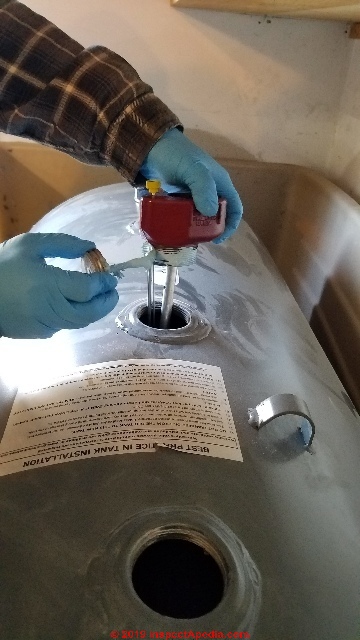
For pipe thread sealant, the installers are using a product specifically rated for use on fuel oil piping connections.
Watch out: Using the wrong type of pipe dope can result in leaks that will be a nasty pain in the neck to fix later.
With the gauge hand-threaded (NOT cross-threaded) into the oil tank vent line tapping the Scully gauge and alarm assembly is tightened into place.
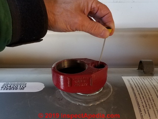
Below: a view into the Scully VentAlarm® and oil gauge assembly shows the actual whistling device in the vent system - that screened disc with a hole in the middle.
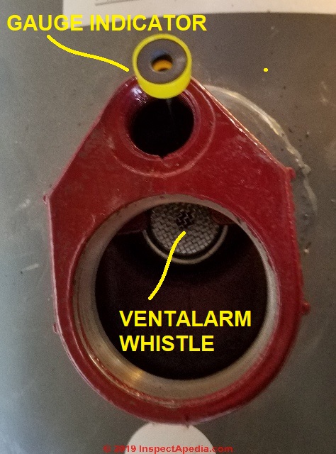
The screen over the Ventalarm® or "tank whistle" serves to keep bugs and crud from falling down the oil tank vent and into the alarm where they might cause it to malfunction.
See more details
at OIL TANK GAUGE & VENT ALARM INSTALL / REPLACE
Step 10: Install the oil piping between oil tank and oil burner
Below: the 42" long supply dip tube and 6" long oil return line tube that will insert into the oil tank at the oil line tapping opening are being prepared for later installation in step 13.
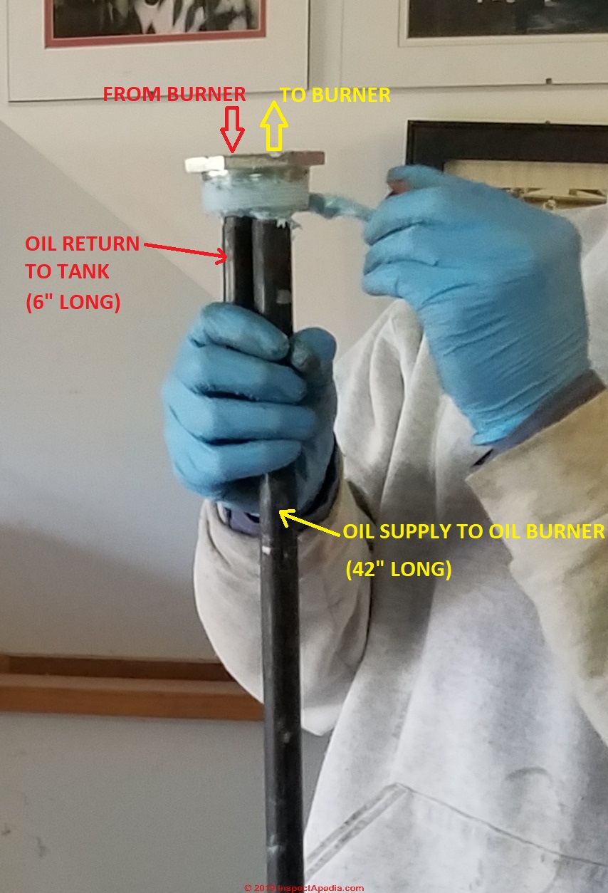
The dip tube places the oil pick-up about 2" off of the bottom of the oil tank, avoiding drawing sludge or water into the oil feed to the oil burner.
Watch out: if there is water or sludge in your oil tank, even with a dip tube that is clear of the bottom, an oil delivery stirs up sludge and crud sufficient to send it to the oil burner.
A delay in running the oil burner of an hour or more would be smart but nobody does that - so you will be relying on that annual oil burner service to include changing the oil filter cartridge and the filter screen inside the fuel unit.
Step 11: Re-Fill the New Oil Tank with Heating Oil
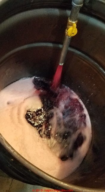
With the new (replacement) oil tank set in place and the fuel gauge mounted, the installers reverse the pumping of heating oil from the temporary 55-gallon drums back into the new tank.
Plumbing the remaining oil tank connections continues while the oil tank is being refilled with heating oil.
You may notice that this heating oil is dyed red, a feature of home heating oil intended to prevent abuse of fuel tax laws.
While your diesel Dodge may run on both diesel purchased at a Getty station and on No. 2 home heating oil (which is taxed at a lower rate) using home heating oil in your vehicle is illegal.
The dye allows officials to spot fuel tax cheaters by staining engine components red.
Step 12: Complete Oil Tank Pipe Connections
Above the workers are installing the tank vent - 2" diameter as currently required - at left, to pass through the higher opening in the building wall, while at right the tank tapping is being fitted with the oil pick-up and return line connection.
A sophistication that makes for quality workmanship here is the use of a pipe cutting and threading tool, mounted in the company's service truck.
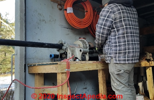
The pipe tool permits the installers to fit the exact fill and vent pipe lengths needed for the job, including routing the new fill and vent pipes out through the building wall at the same locations used for the prior pipe installation.
The oil tank's vent line opening has been drilled out to accommodate the 2-inch diameter vent pipe that replaced an older 1 1/2" line.
Step 13: Route the oil tank supply and return lines from oil tank to oil burner
Below: the 3/8" oil supply and return lines have been connected to fittings at the oil tank.
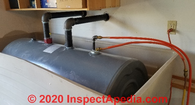
The original oil storage tank at this location was a one-pipe system. It delivered fuel to the oil burner through a tapping at the bottom of the oil tank.
But a bottom-fed oil line is not feasible when local regulations require that the oil tank be installed in a spill-containment tub as shown here. Cutting a hole in the tub bottom to run oil piping would of course render the containment system useless. So a 2-line oil piping system is required when a containment tub is used.
The lower of the two oil lines is the supply line and the oil return line is connected to the higher 1/2" ID iron pipe nipple and elbow that screw into the top of the 4-tap duplex cast iron fitting.
The other two taps are on the fitting's under-side and carry the dip tube and return tube that are now out of view (see step 10 above), having now been inserted into the oil tank.
The oil lines are run in a protected route along the floor abutting the building's walls.
Later we will provide more complete protection for these oil lines using floor trim installed with care not to drive a nail or screw through the oil tubing.
Step 14: Connect oil supply & return piping to the oil burner
Here the installers have completed piping the oil supply and return lines to the fuel unit on the oil burner - as labeled in our photo.
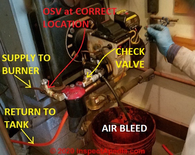
Above: that black tube is connected to the oil burners air bleeder valve. The technician has installed temporary jumper wires at the oil burner control so that he can cause the burner motor to run in order to bleed air from the system.
Watch out: air left in an oil burner piping system or air leaks into the piping will cause improper oil burner shut-down, leaving incompletely burned oil in the combustion chamber - a mistake that can lead to a dangerous oil burner puffback.
Details are at OIL BURNER PUFFBACK EXPLOSION
The installers take considerable care to assure that the oil burner is working properly before leaving the job, including checking oil burner operation, noise, smoke, smoothness, cleanliness, and making multiple checks of the oil piping and all fittings to be sure they're not leaking.
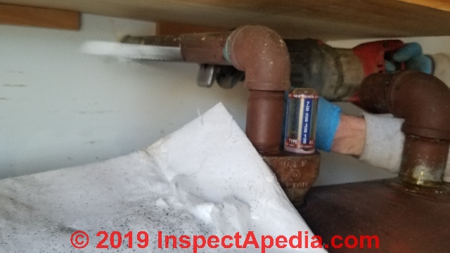
At this installation the original oil burner piping had been incorrect: the oil safety valve (OSV) had been installed on the outlet rather than the inlet side of the oil filter.
The installer also added a check valve between the oil filter and the fuel unit on the oil burner.
Watch out: Note that there are no valves of any kind installed on the oil return line. Any device that could stop the oil return line of a 2-pipe oil burner set-up risks blown oil pump seals that could lead to a serious building fire.
Below is a photo of the same oil burner piping before the oil tank replacement, showing the OSV at the wrong location.
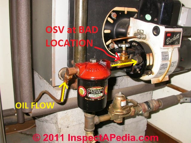
Watch out: in our photo of a fusible link oil line shutoff valve shown just above, the valve is not installed correctly.
Because the original oil burner piping had been bottom-fed from the oil tank there was added risk that the disturbance of the system (or even a recent fuel delivery) may have stirred sludge that then entered and fouled the oil burner.
As part of restoring the burner to service the technician replaced the oil burner filter cartridge and the fuel unit screen in the oil burner pump itself. These are NOT normal oil tank replacement tasks but were performed in part because on restoration of service the burner was operating more poorly than before.
The owner provided the necessary fuel filter cartridge, fuel unit screen and gasket. The technicians made sure the burner was running smoothly.
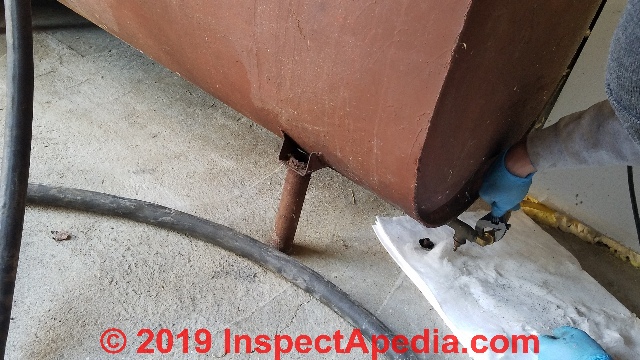
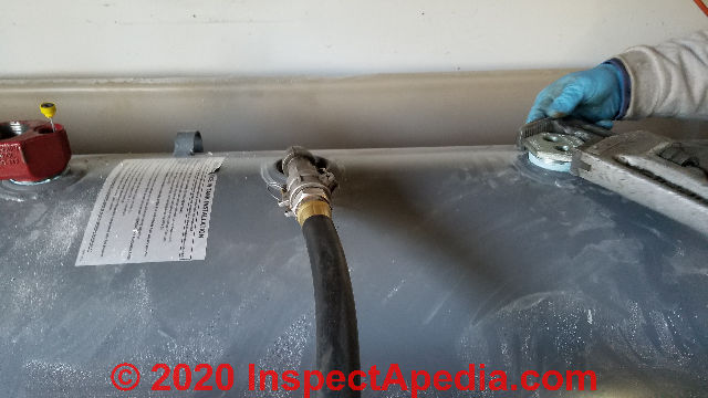
Step 15: Complete outside oil fill & vent piping
Outside the installers complete the oil tank piping by installing the riser and cap on the oil vent line (at right), and by installing that white oil spill containment unit at the oil filler pipe.
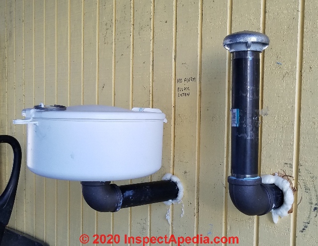
The containment unit is a Morrison Brothers Co. product and is intended to catch drips and slurps from the oil fill nozzle during oil tank filling. This device is not found on most residential oil fill pipes but was required at this location because of the total volume of oil stored at the site.
That little note written on the wall stating "NO ALARM, PLEASE LISTEN" was a clue to the oil delivery driver to reduce the frequency of over-filling the oil tank - a mistake that can lead to seepage leaks around the oil tank gauge or at the fill and vent piping.
The note needed to be changed. The replacement oil tank piping included a Scully VentAlarm that will notify the oil delivery driver (whistling stops) when to stop pumping oil into the tank.
We amended the note to read "HAS ALARM, PLEASE LISTEN".
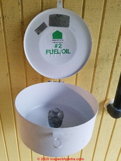
On a label inside the fill pipe containment unit, among other instructions manufacturer warns:
It is the responsibility of the operator to continuously monitor the tank filling process, remain in constant attendance at the discharge control valve, and take all necessary precautions to prevent any spill.
The operator shall ensure the delivery hose is not removed from the tank fill pipe until the hose has been completely drained. - Morrison Bros. Co. - 570 E. 7th St., Dubuque IA 52001
The VentAlarm is a whistling device that is integral with the tank gauge assembly and oil vent attachment fitting at the oil tank.
As the oil tank is filled, air pushed out of the tank by incoming oil sounds a whistle that stops when the alarm's tube opening (shown below) is covered by heating oil rising in the oil tank.
You can see the entire assembly of the Ventalarm® or "whistle-stop" signal and oil tank gauge and float assembly back at Step 9 above.
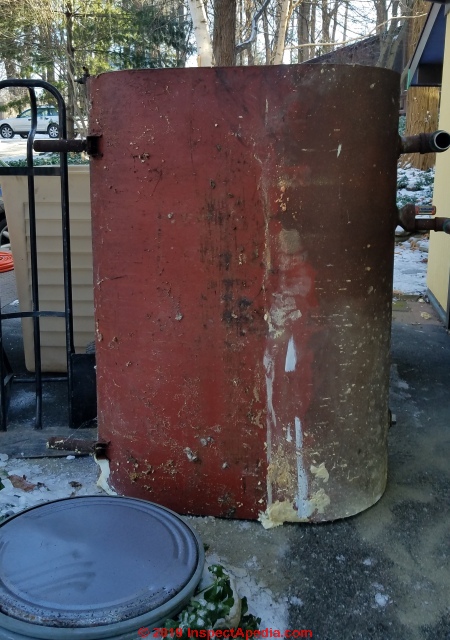
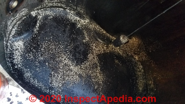
Step 16: Inspecting for Leak Clues on Old Oil Storage Tank
The tank has already been replaced. This is closing the barn after the horse is out frolicking in the hills. But for academic reasons we wanted to inspect the condition of the tank up-close.
The old oil storage tank, now outside, was available for close inspection on all sides.
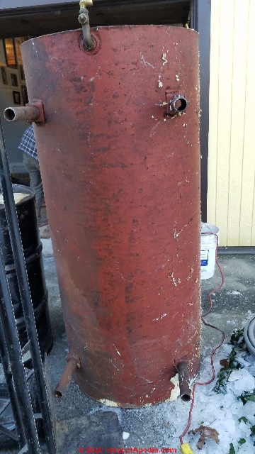
Leaks in oil storage tanks develop mostly in the bottom portion of the tank where the conglomerate of water (on the bottom) and oil and bacteria (living at the oil-water interface) conspire to corrode at that oil-water interface.
The installers pointed out that another common oil storage tank leak point is around the weld where the tank bottom tapping has been installed.
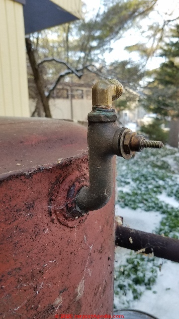
We confirmed that this particular oil storage tank was not leaking and had never leaked with th exception of some seepage at the oil tank fill gauge when over-filled.
Nevertheless the volume of sludge in the tank bottom and the risk of recurrent oil burner failures combined with the age of the tank argue for replacement.
More information is at OIL TANK SLUDGE
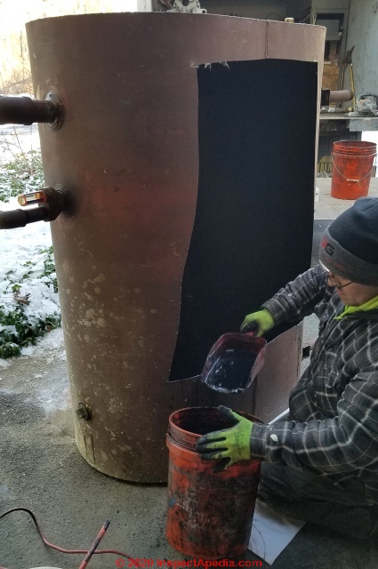
Step 17: Open the old oil tank, remove sludge, clean the tank for disposal
Normally the old oil tank is removed from the job-site intact, taken to the environmental facility where the tank must be cut open, oil sludge removed (for proper disposal), and the tank interior cleaned before the tank can then be disposed of, perhaps as scrap metal.
The installers generously agreed to cut this oil tank open at the jobsite so that we could see the volume and nature of forty+ years of sludge in the container.
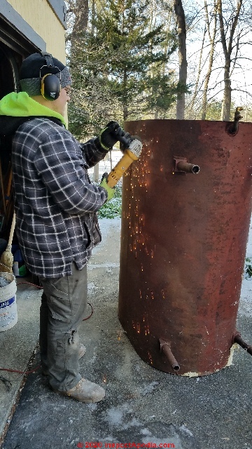
With the oil tank standing on one end, the technician first uses a metal-cutting blade (and appropriate personal protective gear) to cut corner-openings to form a large rectangular cutout on the tank side.
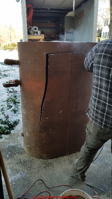
With those pilot-cuts complete, a Sawzall® with a coarse metal-cutting blade is used to saw a large working opening in the tank side.
Note that the technician keeps his cut well above the tank end that's on the ground so as to prevent any oil spillage.
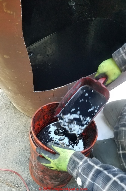
The large rectangular cut is necessary to give safe working room to reach into the oil tank to scoop out the mucky sludge found there. In addition to thick sludge we found bits of debris and remains of a previously fallen oil tank float gauge.
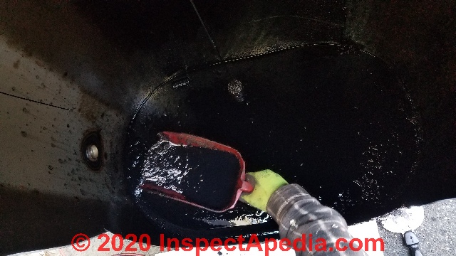
When most of the sludge has been removed from the tank the worker pours in bentonite clay (OK it's basically kitty litter) to absorb the remaining fuel oil remains.
Those are then scooped out of the tank and into a sealable drum for proper disposal as waste oil. In North America, oil sludge and waste disposal are regulated by federal and/or state or provincial laws that vary by jurisdiction.
For its last cleanup step, the abandoned oil tank - i.e. the "removed" old oil tank - is wiped clean with disposable wipes.
Step 18: Complete Protection of Oil Lines: Tank to Burner
In some installations additional steps may be needed to protect the oil lines between oil tank and oil burner. Kicking, stepping-on, or placing stored items atop copper oil lines is a bad idea.
Jiggling these lines around risks loosening a connector, causing a leak and oil burner failure, and stomping on or nicking the lines risks a more extensive oil spill in the building.
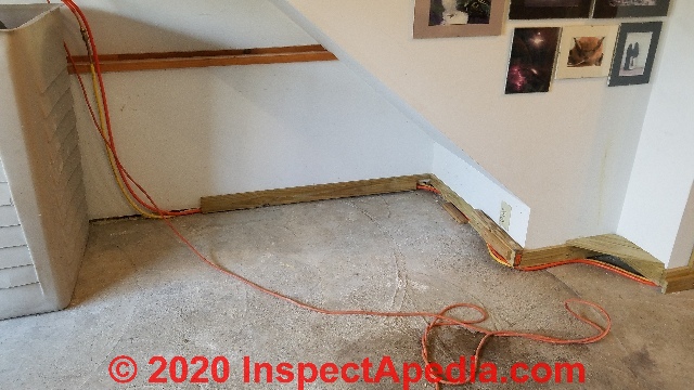
Above: we added wooden kick-boards to assure that no one can push furniture or stored items up against or atop the oil lines.
These tasks are not usually the responsibility of the company replacing the oil tank.
Above: we added wood trim and buffers to assure that as stored items were returned to the garage where this oil tank was installed the storage cannot bang, mash, or otherwise harass the oil piping.
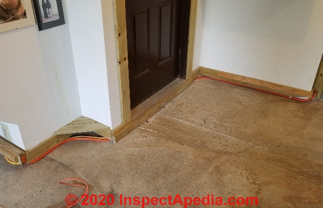
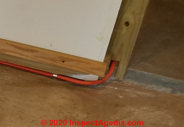
Above and in detail below: particularly important is the protection of oil piping where it runs below a door or across a walking passage. We installed a wooden kick board to keep the copper lines out of the way and protected from damage below that door.
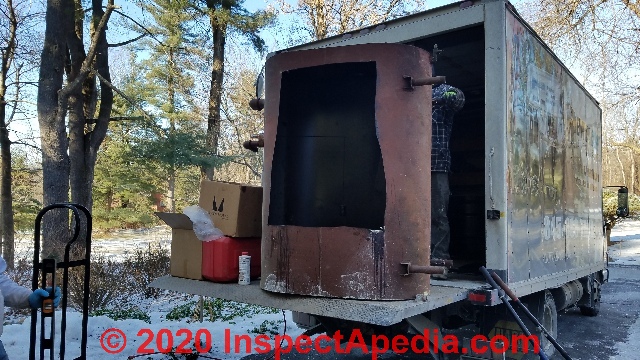
Step 19: Jobsite Cleanup
The workers clean the work area and prepare to haul away the old oil storage tank.
With the building's heat restored, the additional time taken to thoroughly clean the work-site also gives added time to observe the oil fired equipment and to be certain that it is left working properly.
Step 20: Optional Features: Cover the Oil Tank Containment Bin
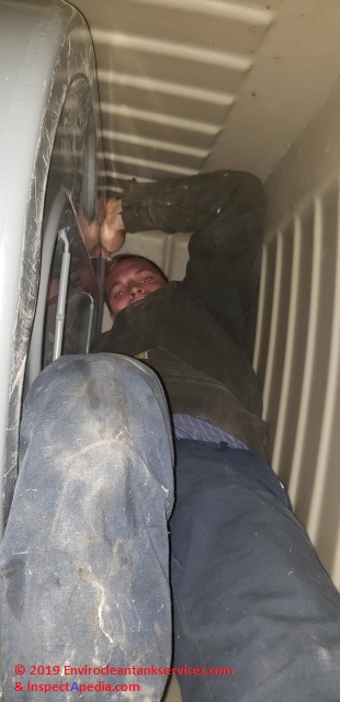
Watch out: With the new oil tank cozy in it's enormous poly "containment bin" it will become quickly apparent that if you drop anything down into the bin it's going to be nearly impossible to retrieve it.
When this containment bin is provided at an outdoor aboveground oil storage tank installation, the company provides a hinged weather-tight peaked "roof" that both sheds rainwater (otherwise your tank bin becomes a tank swimming pool of stagnant water) and that prevents or at least makes it more difficult to drop stuff into the bin.
But an indoor oil storage tank containment system like the one shown here just invites trouble. Besides the intended role of catching any oil tank leaks over the new oil tank's extended life, these containment bins have a magic attraction to "stuff" that will be drawn into them.
The photo, courtesy of our replacement oil tank installers, illustrates the difficulties involved in retrieving stuff dropped into one of these Tankmate bins.
For that reason you may want to finish the job with a cover over the whole installation.
Really? To be perfectly honest, in less than two hours after the new oil tank installers had left the jobsite, in the course of photo-documenting the project and then helping the owners restore items to the garage I dropped things into the tank bin four times.
- My flashlight includes a magnet; it was retrieved by reaching into the tank tub with a steel hand-saw.
- Some paper towels were fished out with a stick.
- Two wood scraps were fished out with a pair of sticks.
Below: is the "Tankmate" oil tank leak containment tub produced by Oil Storage Solutions.
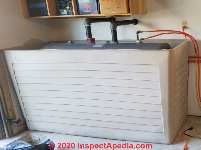
Our next photo below shows lightweight plywood in place over the tank top and tank bin.
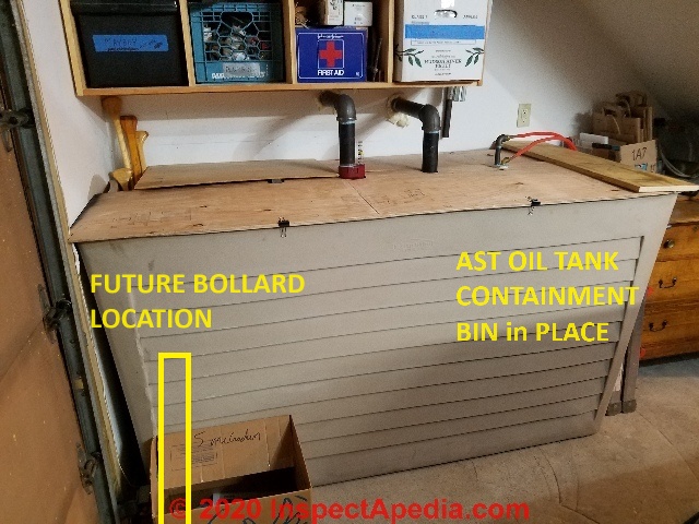
The top of a standard 275-gallon oil tank will stick up slightly above the top edges of the Tankmate. It's easiest to cut four pieces of plywood to simply lay atop the bin edges and to rest atop the oil tank upper surface.
To have our removable tank cover fit nicely, we simply cut a few holes and notches in the 1/4" thick plywood to form covers that can be placed over the tank tub.
You could use anything at hand, even heavy cardboard. Be sure that your oil tank bin covers can be easily removed for inspection of the tank. These sections simply lift away.
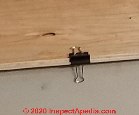
The notches or holes to clear the four tank top tappings or pipe connection points will basically hold the plywood in place. You don't have to do much else. We added a couple of spring clips to hold the plywood neatly to the edges of the oil tank spill containment tub.
While this step is not part of an oil tank replacement job, we include here one final measure: the installation of a remote read-out oil tank level gauge that permits monitoring of the oil level at this building.
Later, with the tank bin safely protected against stealing more tools, cameras, and parts, we used the fourth tank top tapping to install a Smart Oil Gauge™ that uses a Wi-Fi connection to transmit oil tank fuel levels to a smartphone.
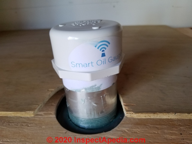
Frankly, one reason that the Smart Gauge installation went quickly and easily was that it was impossible to drop tools (or one's cellphone) into the oil tank containment bin.
Thanks to Larry Roosa and Enviro Clean Oil Tank Services, who performed the oil tank replacement shown above.
The company's steps in installing a protective bollard at the same oil tank can be seen at
at PROTECTION BOLLARDS for MECHANICAL EQUIPMENT
- Enviro Clean Oil Tank Services, Box 454 Wurtsoboro NY 12790, USA, Tel: 845-888-8265 Email: info@envirocleants.com Website: https://www.envirocleantankservices.com/
Details about installing this gauge are
at OIL TANK GAUGE SMART WIFI INSTALLATION.
Best Practice in Oil Tank Installation
Granby Industries, in a sticker on the company's new 275 gallon oil storage tank illustrated here lists a dozen best practices and on the same tag (doubtless written by the company's lawyers) advises: "Warranty is valid provided manufacturer's instructions are respected."
Comment: Granby's warranty pertinent to the ULC-S602 oil storage tank (cited below) is headed by a comment noting that the tank warranty is for tanks sold and installed in Canada after January 1, 2018.
- DO NOT transfer oil from the old tank to this new tank.
Comment: Granby notes that "Most premature failures of steel oil tanks are caused by water and sludge that accumulate at the bottom of the tank." (Granby 2018)
Really: Well maybe not always. Presumably the procedure followed by the oil tank installers shown here avoids the concern of transferring contaminants, water, sludge, by pumping the existing oil storage tank's No. 2 heating oil into temporary storage drums (55 gal) and later pumping that oil into the new tank. - Don't pressure test:
This tank has been pressure tested at factory. Unless local codes dictate otherwise, do not pressure test. - Remove water or ice:
Before installation, remove all water and/or ice that may have accumulated during storage of the tank. - Comply with applicable codes:
Install in accordance with the authorities having jurisdiction, local building codes and NFPA 31 - Don't use for transport:
This tank is intended for stationary use only. - Tilt tank 1/4" per foot
toward the bottom open even if a top draw fuel supply system is used.
Comment: perhaps this is to permit removal of water at the tank bottom tapping? - Inspect tank at least annually
per instructions and regulations from the authorities having jurisdiction.
Really: this tank was installed in a polyethylene barrier container in accordance with New York regulations pertaining to sites where larger quantity of oil are present on-site. The container will prohibit visual access to most of the oil tank. In nearly 50 years of construction, mechanicals work, oil heat service, and building inspection, I have not once found a residential property owner who made an annual oil tank inspection for leaks or damage. - Check for water:
Use water paste dip test to check for accumulated water at least once per year - remove any accumulated water.
Really: this is great advice but as with oil tank inspections, I have never found a single residential property owner using oil heat who follows this advice. However it's trivially easy to check the tank and piping system for water in the canister at the oil burner during annual service. You should ask your heating service technician to make that check.
See details at OIL TANK WATER CONTAMINATION - Vent pipe diameter
must be in accordance with latest version of NFPA 31.
See details at OIL TANK FILL & VENT PIPING INSPECTION CHECKLIST - Witness the first filling
of the tank to verify the integrity of the tank connections. - Remove all temporary shipping caps and plug any unused openings.
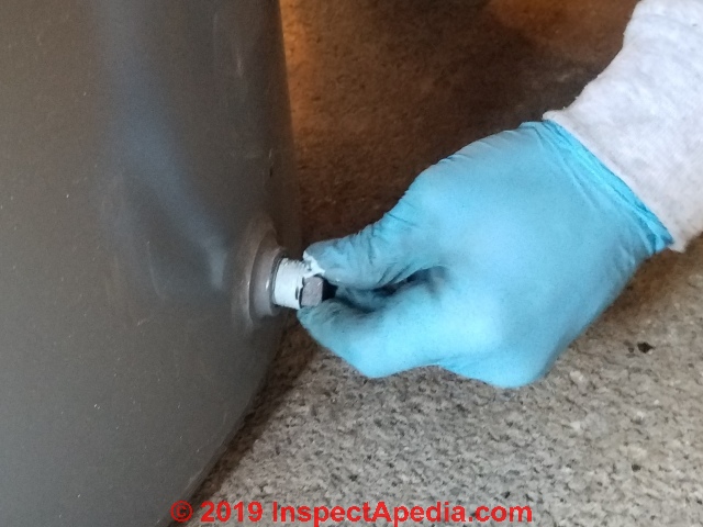
This is done by the installers during tank hook-up. - Refer to recommended best practice
when installing a threaded component into the bottom of the tank as described on the label next to the tank outlet.
Really: as you see in our photo below, there was no label next to the tank bottom outlet tapping.
Guidelines & Standards for AST Oil Tank Replacement
- Canada, Northwest Territories HOMEOWNER'S GUIDE to OIL TANKS [PDF] Northwest Territories, Environment and Natural Resources
PO Box 1320
Yellowknife, NT X1A 2L9 Canada, Tel: 1-867-767-9055 - retrieved 2022/08/19, original source: https://www.enr.gov.nt.ca/sites/enr/files/brochures/homeowners_guide_oil_tanks.pdf
Excerpts:
Large, unexpected bills can be a home and business owner’s nightmare.
An improperly installed and/ or poorly maintained oil tank can leak or spill unexpectedly, often costing in the tens to hundreds of thousands of dollars and be harmful to people, your property and the environment.
It is the legal and financial responsibility of the homeowner, commercial building owners and/or property managers to clean up all heating oil tank leaks and spills.
The Department of Environment and Natural Resources has developed this Homeowner’s Guide to Oil Tanks to help prevent this unwelcome surprise. This Guide is intended to:
act as a pollution prevention measure;
alert home, building and property owners about the potential environmental and financial liability of an oil spill; and •
provide some simple, practical steps that can minimize the chances of an oil spill. - Canada, Storage Tank Systems for Petroleum Products and Allied Petroleum Products Regulations Web: http://www.ec.gc.ca/st-rs/
- Canada, Government of the Northwest Territories, Department of Environment and Natural Resources. Check Your Heating Fuel Tank! http://www.enr.gov.nt.ca/_live/documents/ documentManagerUpload/check_your_heating_fuel_ tank.pdf
- Canada, Nova Scotia, INSTALLATION AND ENVIRONMENTAL MANAGEMENT GUIDE FOR
ABOVEGROUND DOMESTIC OIL TANKS
IN NOVA SCOTIA [PDF] (2007) Government of Nova Scotia, Tel: 1-800-670-4357, Web: https://beta.novascotia.ca/contact-us - retrieved 2022/08/19, original source: https://novascotia.ca/nse/petroleum/docs/OilTankInstall.pdf
Excerpts:
This guide applies to the installation and environmental managem ent of domestic aboveground fuel oil storage tanks constructed to CAN/ULC-S602, “Standard for Aboveground Steel Tanks for Fuel Oil and Lubricating Oil” as revised, amended or substituted; or ULC/ORD C80.1, “Aboveground NonMetallic Tanks for Fuel Oil” as revised, amended or substituted.
The guide does not apply to aboveground fuel oil tank systems having a nominal capacity of 2500 Litres (550 imp gallons) or greater. Tank systems having a nominal capacity in excess of 2500 Litres (550 imp gallons) but less than 4000 Litres (880 Imp Gallons) are regulated through the Fuel Safety Regulations, and are to be installed in accordance with the Canadian Standards Association’s CSA B-139, latest recognized edition, “Installation Code for Oil Burning Equipment” and the “National Fire Code of Canada”, latest edition.
Tank systems having a nominal capacity in excess of 4000 L are regulated through the Nova Scotia Petroleum Management Regulations. - Canadian Council of Ministers of the Environment. Environmental Code of Practice for Aboveground and Underground Storage Tank Systems Containing Petroleum and Allied Petroleum Products. 2003. http://www.ec.gc.ca/st-rs/default asp?lang=En&n=06EF27CF-1
- Granby, INSTALLATION AND MAINTENANCE GUIDELINES FOR ABOVEGROUND STEEL TANKS FOR FUEL OIL AND LUBRICATING OIL [PDF] (2018) Granby Industries LLP., 98, rue des Industries, Cowansville, Quebec J2K 0A1, Canada Tel: 450-378-2334 Website: www.granbyindustries.com Email: sales@granbyindustries.wp.vortexdev.com retrieved 2019/12/30 original source: https://www.granbyindustries.com/wp-content/uploads/2018/02/SI0007_Na-ULC-S602-INSTALLATION-AND-MAINTENANCE-GUIDELINES.pdf
- Granby Oil Tank Warranty for ULC-S602 [PDF] Op. Cit. retrieved 2019/12/30 original source: https://www.granbyindustries.com/wp-content/uploads/2017/12/WARR.021.CE_.0118_Granby-ULC-S602-Warranty.pdf
- "Homeowners Guide to Fuel Storage," Agway Energy Products, Verbank, NY, November 1990
- NFPA 31 Standard for the Installation of Oil-Burning Equipment (2016) available from NFPA, Website excerpt:
NFPA 31 is the benchmark for the correct installation of boilers, air heaters, and other liquid fuel-burning equipment, and their fuel supplies.
Designers, contractors, and installers rely on this Standard for guidance that protects property and building occupants by ensuring a fire-safe installation. Authorities Having Jurisdiction (AHJs) and insurance underwriters depend on NFPA 31 requirements to verify the safety of installations in industrial, commercial, and residential occupancies.
The Standard covers all liquid fuels that are approved for use in oil-burning appliances. In addition to addressing heating appliances that use No. 2 fuel oil and other petroleum-based oils, the Standard includes requirements for appliances that use other acceptable fuels -- including biodiesel blends, biofuels, and recycled lubrication oil.
Comprehensive chapters present requirements for the installation and operation of appliances, air for combustion and ventilation, venting of combustion gases, and storage tanks and piping systems for liquid fuels. - Oil Storage Solutions 35 Mill St, Amityville NY 11757 USA Tel/Fax: (631) 608-8888 Mobile: (917) 887-9568 e-Mail: tanktray@gmail.com provides secondary oil storage tank containment tubs meeting US SPCC codes for oil containment including 40 CFR 112. Tel: 1-877-4-TANKMATE Website: https://www.oilstoragesolutions.com/
- Gil-Fab, DWOT Fuel Oil Storage Tanks LICENSED INSTALLER INSTRUCTIONS [PDF] for Single Tank Installations, for aboveground nonmetallic tank for fuel oil & other combustible liquids, GIL-FAB Tanks International 1429 De la Gare Mascouche, QC, Canada J7K 3G6 Website: www.ats-tanks.com/UL2258 retrieved 2019/10/25 original source: https://images.homedepot-static.com/catalog/pdfImages/fd/fdd89385-9677-470a-9c17-ddc408ec6060.pdf
- Roth Fuel Level Gauges described in EcoDWT Plus 3 oil storage tank [Installation Instructions] [PDF] Roth Industries
268 Bellew Ave South
Watertown, NY 13601 USA Website: http://www.roth-usa.com retrieved 2019/10/25 original source: http://www.roth-usa.com/PDF_Download_Files/DWT_install_instructions.pdf
Excerpt:
Roth has an optional fuel level gauge that can be installed in the EcoDWT plus 3. These are sealed gauges and have 2” threaded connections with “O” ring seals and cord style floats.
- Scully, SCULLY TANK & UNIFILL® Catalog [PDF] (2017) World Headquarters
Scully Signal Company
70 Industrial Way
Wilmington, MA 01887
USA
Phone: 617-692-8601
or 1-800-272-8559 Fax: 617-692-8620
Sales@scully.com
Applications@scully.com - this catalog illustrates several types of oil tank fill / vent alarms and oil tank gauges.
Scully UK Meridian House Unit 33 37 Road One Winsford Industrial Estate Winsford, Cheshire CW7 3QG Phone: +44 (0)1606 553805 Fax: +44 (0)1606 553824 Sales@scullyuk.com
Scully Europe Maanstraat 25 2800 Mechelen Belgium Phone: +32(0)15560070 Fax: +32(0)15550070 Sales@scully.be
retrieved 2019/10/25 original source: http://www.scully.com/wp-content/uploads/2015/04/Scully-Oil-Delivery-Catalog_TankUNIFIL_2017.pdf?d2ec2a&d2ec2a - Scully, Ventalarm® Combination Whistle Alarm & OIL TANK LEVEL INDICATOR Data Sheet [PDF] (2015), op. cit.
Note that the Ventalarm is sold in 1 1/2" and 2" diameter fittings to correspond to those oil tank opening sizes, and the oil tank gauge mechanism is sold in different models corresponding to different oil tank depths. - Scully, SCULLY WHISTLER TANK ALARM INSTALLATION INSTRUCTIONS [PDF] Scully, Op. Cit.
- TankTub, TANK TUB INSTALLATION INSTRUCTIONS [PDF]
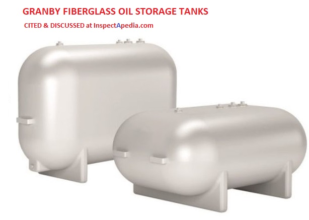
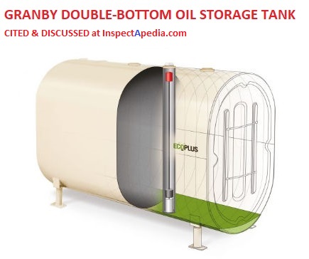
Replacement Oil Tanks: Plastic, Double-Walled, Containment Systems
Shown here are examples of some heating oil storage tank types provided by Granby Industries,
- Granby Industries L.P.
98, rue des Industries, Cowansville, Québec J2K 0A1, Canada
T 450-378-2334
F 450-378-5202 sales@granbyindustries.com
USA @ bcullity@granbyindustries.com sales@granbyindustries.com retrieved 2020/02/24 original source: https://www.granbyindustries.com/en-us/petroleum-tanks/categories/residential-oil-tanks-en-us/
Fiberglass heating oil storage tank
Double-walled heating oil storage tank with secondary containment. Not visible is the primary oil tank made of "blow-molded high-density polyethylene (HDPE).
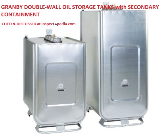
The secondary (exterior) containment tank is made of welded and edged galvanized steel.
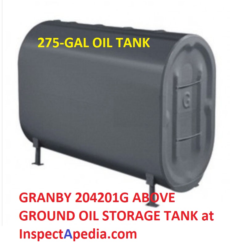
Granby also provides standard steel oil storage tanks (above) like the one we installed
at OIL TANK REPLACEMENT PROCEDURE as well as double-bottom oil storage tanks that include polyurethane and UV protection liner.
Other plastic, double wall and containment-system oil storage tank providers include
- Roth Double Wall Storage Tanks (DWTs), Roth Industries, Inc.
268 Bellew Ave South
Watertown, NY 13601
Toll Free US: 888-266-7684
info@roth-usa.com
For Canadian customers:
Toll Free Canada: 888-266-7684
service@roth-canada.com
Roth Global Plastics, Inc. P.O. Box 245 Syracuse, NY 13211 Toll Free: 866-943-7256 sales@roth-usa.com - USP United States Plastic Corp. 1390 Neubrecht Rd. Lima, OH 45801 800-809-4217 Corporate Office 419-228-2242 usp@usplastic.com Tech Support – Sales 8am - 5pm M-F 800-821-0349 techsupport@usplastic.com
...
Continue reading at INDOOR OIL TANK ABANDONMENT or select a topic from the closely-related articles below, or see the complete ARTICLE INDEX.
Or see these
Recommended Articles
- INDOOR OIL TANK ABANDONMENT - using up heating oil or removing it from an oil tank
- OIL TANK FILL & VENT PIPING INSPECTION CHECKLIST
- OIL TANK GAUGES - home
- OIL STORAGE TANKS - home
- OIL TANK LEAK & ABANDONMENT REGULATIONS
- OIL TANK AGE
- OIL TANK GAUGE & VENT ALARM INSTALL / REPLACE
- OIL TANK GAUGE SMART WIFI INSTALLATION
- OIL TANK PRESSURE
- OIL TANK LEAK & ABANDONMENT REGULATIONS
- OIL TANK REPLACE due to SLUDGE?
- OIL TANK REPLACEMENT PROCEDURE
- OIL TANK SAFETY
- OIL TANK SLUDGE
- OIL TANK STANDARDS - UL
- OIL TANK WATER REMOVAL
- OIL TANK ABANDONING PROCEDURE
- ABOVE GROUND OIL STORAGE TANKS (AST) GUIDE - home
- BURIED OIL STORAGE TANKS - home
- OIL TANK LEAK & ODOR ADVICE
- OIL TANK LIFE for ASTs and USTs
- OIL TANK PIPING & PIPING DEFECTS - home
- PROTECTION BOLLARDS for MECHANICAL EQUIPMENT
Suggested citation for this web page
OIL TANK REPLACEMENT PROCEDURE at InspectApedia.com - online encyclopedia of building & environmental inspection, testing, diagnosis, repair, & problem prevention advice.
Or see this
INDEX to RELATED ARTICLES: ARTICLE INDEX to HEATING OIL, OIL BURNERS, OIL FIRED HEATERS, OIL TANKS
Or use the SEARCH BOX found below to Ask a Question or Search InspectApedia
Ask a Question or Search InspectApedia
Try the search box just below, or if you prefer, post a question or comment in the Comments box below and we will respond promptly.
Search the InspectApedia website
Note: appearance of your Comment below may be delayed: if your comment contains an image, photograph, web link, or text that looks to the software as if it might be a web link, your posting will appear after it has been approved by a moderator. Apologies for the delay.
Only one image can be added per comment but you can post as many comments, and therefore images, as you like.
You will not receive a notification when a response to your question has been posted.
Please bookmark this page to make it easy for you to check back for our response.
IF above you see "Comment Form is loading comments..." then COMMENT BOX - countable.ca / bawkbox.com IS NOT WORKING.
In any case you are welcome to send an email directly to us at InspectApedia.com at editor@inspectApedia.com
We'll reply to you directly. Please help us help you by noting, in your email, the URL of the InspectApedia page where you wanted to comment.
Citations & References
In addition to any citations in the article above, a full list is available on request.
- In addition to citations & references found in this article, see the research citations given at the end of the related articles found at our suggested
CONTINUE READING or RECOMMENDED ARTICLES.
- Carson, Dunlop & Associates Ltd., 120 Carlton Street Suite 407, Toronto ON M5A 4K2. Tel: (416) 964-9415 1-800-268-7070 Email: info@carsondunlop.com. Alan Carson is a past president of ASHI, the American Society of Home Inspectors.
Thanks to Alan Carson and Bob Dunlop, for permission for InspectAPedia to use text excerpts from The HOME REFERENCE BOOK - the Encyclopedia of Homes and to use illustrations from The ILLUSTRATED HOME .
Carson Dunlop Associates provides extensive home inspection education and report writing material. In gratitude we provide links to tsome Carson Dunlop Associates products and services.
 | HOME | ABOUT | ASK a QUESTION | CONTACT | CONTENT USE POLICY | DESCRIPTION | POLICIES | PRIVACY | |
| © 2025 - 1985 Publisher InspectApedia.com - Daniel Friedman | |||||||||