 Ground Fault Circuit Interrupters, GFCI Test Procedure
How to Test a GFCI
- POST a QUESTION or COMMENT about ground fault circuit interrupters
Ground Fault Circuit Interrupters, GFCI testing:
Here we cite expert sources' description of the proper way to test a ground fault circuit interruptor GFCI for proper and safe operation.
We include additional notes on situations in which proper testing is impossible even though the device might actually work if a current leak to ground or neutral occurs on the circuit.
This article series GFCIs and AFCIs as well as safe GFCI & AFCI installation, wiring, testing, and inspection.
InspectAPedia tolerates no conflicts of interest. We have no relationship with advertisers, products, or services discussed at this website.
- Daniel Friedman, Publisher/Editor/Author - See WHO ARE WE?
GFCI Testing Instructions
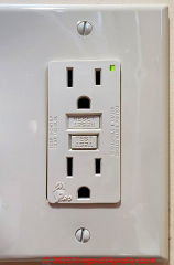 A GFCI or Ground-Fault Circuit Interrupter is a safety device intended to prevent electrical shock by detecting an improper flow of electrical current and shutting the electrical circuit off very quickly - in milliseconds.
The GFCI is designed to protect people from severe or fatal electric shocks by quickly detecting a small flow of electrical current between the electrical circuit (wires, switch, electrical receptacle or something plugged-in to the receptacle) and "ground" or the earth.
A GFCI also can protect against some electrical fires by detecting arcing and other faults to ground but a GFCI cannot detect hazardous across-the-line arcing faults that can cause fires.
[Click to enlarge any image]
The photo also shows an independent GFCI test tool plugged into the lower receptacle openings.
On the GFCI tester the round black button on the top of the devicve is an independent test button that attempts to simulate a short to ground or neutral. If the device tester trips the GFCI the RED RESET button will pop out as above.
GFCI Test Procedure for Receptacles: Using the Receptacle Built-In Test & Reset Buttons
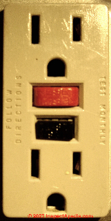
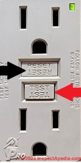
On many GFCI wall receptacles the TEST button is red and the RESET button is black (photo above), but as you can see in our earlier photo above and in a closer view below, on other models there is no color code.
You'll notice in our photo below that one button is emossed with the word TEST (our red arrow) and the other with the word RESET (our black arrow).
In these photos the GFCI TEST button on the wall receptacle itself checks the wiring connections at the GFCI receptacle.
The RESET button on the electrical GFCI receptacle will pop out if the device is tripped off. Pushing the RESET button all the way in should re-set the device and restore electrical power.
The following GFCI test details are adapted from advice from Eaton CH cited just below.
(a) Turn the power ON at the service panel.
Press the RESET
button fully. Plug a lamp or radio into the GFCI (and leave it
plugged-in) to verify that the power is ON. If there is no power, go
to Troubleshooting.
(b) Press the TEST button in order to trip the device.
This should
stop the flow of electricity, making the radio or lamp shut OFF
and the yellow Correct Wiring/Trip Indicator come on. To restore
power, press the RESET button.
(c) Test Downstream receptacles:
If you installed your GFCI using step 7B, [that stepincludes wiring to protect downstream or surrounding receptacles - Ed.] now plug a lamp or
radio into surrounding receptacles to see which one(s), in
addition to the GFCI, lost power when you press the TEST
button.
Do not plug life saving devices into any receptacles that lost power.
Place a “GFCI Protected” sticker on every receptacle
that lost power.
(d) Press the TEST button (then RESET button) every month to
assure proper operation.
(e) Note that this Eaton GFCI is shipped in the Tripped state and
cannot be Reset until it is wired correctly and powered from it’s
Line terminals.
(f) Note that the RESET button will pop-out. If the power goes OFF and the correct wiring/trip
indicator stays on, you have installed the GFCI receptacle correctly.
(g) LINE/LOAD reversal will be indicated by the reset button not staying in after being pressed.
Such LINE/LOAD reversal will also be indicated by failure of the Correct Wiring/Trip Indicator to be on while the GFCI is tripped.
- source: Eaton, INSTALLING & TESTING a GFCI RECEPTCLE [PDF], Eaton, Website: www.eaton.com or www.cooperwiringdevices.com retrieved 2018/07.27,original source: http://www.cooperindustries.com/content/dam/public/wiringdevices/products/documents/instruction_sheets/EIS-0018-E.pdf
Excerpt:
Watch out: If you miswire the GFCI, it may not prevent personal injury or death due to a ground fault
(electric shock).
Upon initial installation, if you mistakenly connect the LINE wires
to the LOAD terminals, this Eaton GFCI will not be able to be reset,
and will therefore not provide power to it’s receptacle face or load
terminals.
Watch out: the integral test buttons on a GFCI device installed on an electrical circuit that has no ground, such as on a knob and tube circuit will generally not work because the device expects the GFCI device to be connected to an electrical ground (used to simulate a current leak.
However the device might still work properly if there is an actual current leak between the GFCI device or receptacle, or something plugged into-it, and ground or neutral.
More about this test limitation including a discussion of testing GFCI devices installed on knob-and-tube electrical circuits or un-grounded circuits is found
at AFCI GFCI WIRING, TESTING & SAFETY .
GFCI Receptacle Test Procedure using a Plug-In Receptacle Tester
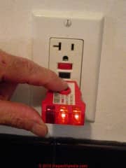 In our photo above, you can see the built-in red TEST and black RESET buttons on this GFCI wall receptacle, but we're going to use an independent test device, the plug-in GFCI receptacle tester that wev'e inserted into the lower openings of the receptacle.
While the wall receptacle's built-in test and reset buttons are useful, this test is less complete than the test made using an external, plug-in test device.
Our photo shows a GFCI tester: the red light is off and the two yellow lights are on, indicating that this receptacle is wired properly.
When we push the black "test" button on our test device the GFCI receptacle should trip OFF.
GFCI Receptacle Test Procedure Details using a plug-in tester
- Correct GFCI wiring:
Plug this receptacle tester into a ground fault circuit interrupter GFCI outlet (which you should have or want in lots of locations in your home such as baths, kitchen, garage, basement, outdoors).
Just by plugging it in the device without pushing its test button (under my finger in the photo) tests to see not only if the GFCI is wired properly. - Nuisance tripping:
Just plugging in the device will also detect if the GFCI is going to trip unnecessarily - nuisance tripping - because the tester includes a built-in but very tiny current leak to ground - less than 14 mA, a current level below that at which the GFCI should trip. - Ground fault detection: now push the test button
Then if you push the black test button the tester will put a 14 mA current leak on to the GFCI to see that the GFCI will trip if a ground fault occurs.
That is, the test checks to see if the GFCI is doing its job. (
Watch out: you can perform the first group of tests above but you cann NOT heck for the presence of a proper electrical ground nor test a GFCI with this device IF the GFCI outlet is connected to a two-wire circuit that lacks a ground path. The GFCI might still trip when it should to protect someone from an electric shock but you can't easily test for that condition.
See ELECTRICAL TOOLS BASIC for details of the meaning of the all combinations of indicator lights on plug-in type wall receptacle testers including GFCI testers in our dicsussion titled " Electrical receptacle tester and GFCI tester (outlet tester)".
How To Re-Set a Tripped Receptacle Type GFCI
Un-Plug any tools or devices that are connected to the receptacle circuit whose GFCI tripped off.
Press and hold the RESET button on the device.
That should re-set the GFCI.
This procedure will usually apply as well to portable GFCI devices such as those discussed
at GFCI DEVICE SELECTION & WIRING
Watch out: If the GFCI will NOT re-set when you press the RESET button it's likely that there is an unsafe condition on the circuit or circuit wiring itself.
In that case leave the circuit switched OFF at the electrical panel and ask for help from a licensed electrician. She will trace the circuit to find the problem such as a short to ground or a short to neutral in circuit wiring.
An example that we encountered was a short to neutral when the screw tightening a clamp that connected flexible metal cable conduit to a metal electrical box was screwed-in too tightly and where the normal plastic bushing inside the fitting had been omitted.
The sharp metal edge of the BX armored cable cut into and shorted the hot and neutral wires together.
More help is at CIRCUIT BREAKER RESET STEPS
GFCI Test Procedure for GFCI Circuit Breakers
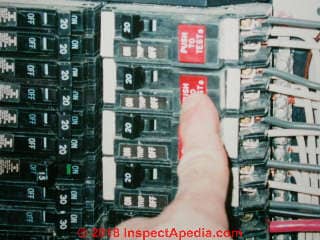
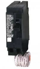
As our illustration shows, a GFCI circuit breaker also has a "TEST" button that is depressed to test the device.
How to Re-Set a Circuit-Breaker Type GFCI
Instead of a reset button such as is found on a GFCI receptacle, on the GFCI circuit breaker the test function will trip the breaker toggle.
You will need to re-set the circuit breaker by
- first moving the toggle first to OFF or on some models past OFF,
- then move it to the ON position.
More help is at CIRCUIT BREAKER RESET STEPS
GFCI Test Procedures, Standards, Documents
- Eaton, INSTALLING & TESTING a GFCI RECEPTCLE [PDF], Eaton, Website: www.eaton.com or www.cooperwiringdevices.com retrieved 2018/07.27,original source: http://www.cooperindustries.com/content/dam/public/wiringdevices/products/documents/instruction_sheets/EIS-0018-E.pdf
- Hubbell, INSTALLING & TESTING a GFCI RECEPTACLE [PDF] , Hubbel Corporation, 40 Waterview Dr., Shelton CT 06484 USA, Website: retrieved 2018/07/27, original source: http://www.arrl.org/files/file/Technology/GroundingAndBonding/Installing%20and%20Testing%20a%20GFCI%20Receptacle.pdf
- Craftsman GFCI RECEPTACLE TESTER INSTRUCTIONS [PDF] Craftsman, Sears brands Management, Hoffman Estates IL 60179 USA, Tel: 800-326-1006 Website: www.craftsman.com,
- Gardner Bender GFCI RECEPTACLE TESTER INSTRUCTIONS [PDF] Gardner Bender Milwaukee WI 53201, Web: www.gardnerbender.com (made in China)
- Ideal, GFCI RECEPTACLE TESTER INSTRUCTIONS [PDF] Ideal Industries
- Klein GFCI RECEPTACLE TESTER INSTRUCTIONS [PDF] Klein Tools, Inc., 450 Bond St., Lincolnshire IL 60089 USA Tel: 800-553-4676, web: www.kleintools.com Email: customerservice@kleintools.com
- Larson Electronics, Tel: 1-877-432-0861 / International: 1-903-498-3363 Email: sales@larsonelectronics.com, Website: larsonelectronics.com Larson provides GFCI protected linecords and other electrical equipment.
- Legrand, INSTALLING and TESTING a GFCI RECEPTACLE [PDF] Pass & Semour Legrand, PO Box 4822, Syracuse NY 13221 USA, Tel: 800-223-4185, Website: www.legrand.us, retrieved 2018/07/27, original source:
Excerpt:
This is a Self-Test GFCI Receptacle with SafeLock Protection™; it conducts an automatic test every three seconds, ensuring it’s always ready to protect. If the device fails the test, the indicator light flashes to signal that the GFCI should be replaced. It also has our proven SafeLock Protection feature: if critical components are damaged and protection is lost, power to this receptacle, and any downstream receptacles, will be disconnected. - Leviton, GFCI INSTALLATION & TEST PROCEDURES [PDF], retrieved 2018/07/27, original source: https://www.leviton.com/en/docs/guidelight.pdf
- Novatech GFCI RECEPTACLE TESTER INSTRUCTIONS [PDF] Novatech, Internatibal, Cole-Parmer & Davis Instruments, Tel: (866) 433-6682 Email: sales@novatech-usa.com Web: www.novatech-usa.com
- Siemens GFCI CIRCUIT BREAKER DATA SHEET & WIRING DIAGRAMS [PDF] retrieved 2018/09/07, original source: siemens.com/gfci
- Siemens CIRCUIT BREAKER & GROUND FAULT CIRCUIT INTERRUPTER Specifications Sheet [PDF] retrieved 2018/09/07, original source: https://gfiwarehouse.com/~gfiwareh/siemensdatasheet.pdf
- Southwire GFCI RECEPTACLE TESTER INSTRUCTIONS [PDF] (2016) Southwire Tools, One Southwire Dr., Carrolton GA 30119 USA (made in China)
- Sperry GFCI RECEPTACLE TESTER INSTRUCTIONS [PDF] Sperry Instruents,
- GFCI WORKPLACE TEST REQUIREMENTS OSHA U.S. OSHA, - retrieved 2018/07.27, original source: www.osha.gov/laws-regs/standardinterpretations/1992-02-10
- U.S. CPSC, What is a GFCI, [PDF] U.S. Consumer Product Safety Commission, retrieved 2018/07.27, original source: https://www.cpsc.gov/s3fs-public/099_0.pdf
- Also see AFCI GFCI WIRING, TESTING & SAFETY
Reader Comments &
On 2021-07-29 by inspectapedia.com.moderator (mod)
@Mack,
The typical plug-in GFCI receptacle tester works by making an internal short to ground - that should work on a conventional receptacle that has GFCI or ground-fault circuit interrupter) protection anywhere upstream from the test point.
That protection can be a GFCI receptacle or it can be a GFCI circuit breaker.
Really? It's interesting (perhaps significant) that the test of GFCI circuit breakers using these tools is NOT mentioned explicitly in any of the receptacle-type GFCI receptacle tester instructions that we provide above on this page - from 7 different sources.
Here are two examples:
GFCI TESTER INSTRUCTIONS, SOUTHWIRE [PDF] https://inspectapedia.com/electric/GFCI-Receptacle-Tester-Instructions-Southwiretools.pdf
GFCU TESTER INSTRUCTIONS, KLEIN TOOLS [PDF] https://inspectapedia.com/electric/GFCI-Receptacle-Tester-Instructions-Kleintools.com.pdf
On 2021-07-29 by Mack
Can a gfci breaker be tested by using a plug tester with the test button
On 2020-03-10 by (mod)
Alan
Thanks for the interesting points - ones that we'll be sure to keep with the article.
Indeed there is probably no GFCI tester on the market that is designed for in-field use that considers trip time.
The good news is that the most-essential, most-common GFCI faults - the ones most-likely to cause a failure and perhaps injury or worse - are not trip times but rather no-trips - a mis-wired GFCI that simply won't trip in response to a current leak to neutral or to ground.
It's also worth noting that the internal test exercised by pushing the test button on a GFCI depends on a proper local ground connection that may be absent entirely in some GFCI installations (such as on 2-wire circuits) - those GFCI's cannot be tested by normal means, even if the GFCI would trip in response to a short to neutral or to some other ground.
On 2020-03-10 by Alan
Before I worked at the mine I worked for an Electrical OEM where we did breaker and ground fault testing.
Anyone who had done breaker testing with current knows the expensive equipment that it takes to do this job. Does not really matter if it is primary or secondary injection.
I was working at a open pit mine in NW when this first reared its ugly head. We were instructed to put a gfci in every location there was water/liquid.
So a coffee pot on a cabinet without a sink qualified. We installed gcfi's by the 100's. Then the inspector came back and said he wanted a testing record for all of the gfci's.
At the time there was no REAL gfci testing equipment out there. I objected to the concept of self testing. We tested grounding in the process building records for all equipment. Required a meter and checking the continuity for all the equipment. ( Lots of work to do this)
I started asking to what standard did the IMSHA inspector wanted these to be tested. He said whatever the manufacturer published.
The self testing issue sprung to the top of the list. Our management and our inspectors did not know there are different levels for gfci's. They were thinking that they were all the same. Until I pointed out gfcis for equipment protection. Which if installed on a personnel circuit could be bad news. They were unaware of those.
I found this on and IEEE page.
"A GFCI de-energizes the circuit when the leakage current level reaches 5 ± 1 mA in 1/40 th of a second. This value of current is well below heart fibrillation levels."
Looking about on the web I found a 8 dollar box from a well know vendor for testing gfci's.
"Tester trips between 6-9 mA" No mention as to the time required to trip.
This box might do a great job for what it was designed to do, how ever I do not call it a tester, a tripper yes, tester no.
My point is most people using these cheap devices are doing themselves and clients a disservice.
I have not looked recently (last 3 years) since I got out of the business. Someone may have come up with a device that really does test, current and time. Bet my government check it is not inexpensive.
...
Continue reading at AFCI GFCI WIRING, TESTING & SAFETY or select a topic from the closely-related articles below, or see the complete ARTICLE INDEX.
Or see AFCI GFCI TESTING & SAFETY FAQs - questions & answers posted originally at this page
Or see this
Article Series
- AFCIs ARC FAULT CIRCUIT INTERRUPTERS
- ELECTRICAL TOOLS BASIC - including plug-in receptacle testers & other tools
- FREEZE-PROOF A BUILDING where we describe GFCI protection on heat tape circuits
- GFCI PROTECTION, GFCI CODES
- GROUND SYSTEM INSPECTION
- SAFETY for ELECTRICAL INSPECTORS - home
- TEST EQUIPMENT, ELECTRICAL GUIDE
Suggested citation for this web page
GFCI TEST PROCEDURES at InspectApedia.com - online encyclopedia of building & environmental inspection, testing, diagnosis, repair, & problem prevention advice.
Or see this
INDEX to RELATED ARTICLES: ARTICLE INDEX to ELECTRICAL INSPECTION & TESTING
Or use the SEARCH BOX found below to Ask a Question or Search InspectApedia
Ask a Question or Search InspectApedia
Try the search box just below, or if you prefer, post a question or comment in the Comments box below and we will respond promptly.
Search the InspectApedia website
Note: appearance of your Comment below may be delayed: if your comment contains an image, photograph, web link, or text that looks to the software as if it might be a web link, your posting will appear after it has been approved by a moderator. Apologies for the delay.
Only one image can be added per comment but you can post as many comments, and therefore images, as you like.
You will not receive a notification when a response to your question has been posted.
Please bookmark this page to make it easy for you to check back for our response.
IF above you see "Comment Form is loading comments..." then COMMENT BOX - countable.ca / bawkbox.com IS NOT WORKING.
In any case you are welcome to send an email directly to us at InspectApedia.com at editor@inspectApedia.com
We'll reply to you directly. Please help us help you by noting, in your email, the URL of the InspectApedia page where you wanted to comment.
Citations & References
In addition to any citations in the article above, a full list is available on request.
- UL 943, Ground-Fault Circuit Interrupters, retrieved 2016/08/08, original source: http://ulstandards.ul.com/standard/?id=943
Excerpt:
1.1 This Standard applies to Class A, single- and three-phase, ground-fault circuit-interrupters intended for protection of personnel, for use only in grounded neutral systems in accordance with the National Electrical Code (NEC), ANSI/NFPA 70, the Canadian Electrical Code, C22.1 (CEC), and Electrical Installations (Use), NOM-001-SEDE. These devices are intended for use on alternating current (AC) circuits of 120 V, 208Y/120 V, 120/240 V, 127 V, or 220Y/127 V, 60 Hz circuits. Note: In Canada, the text "intended for protection of personnel" is excluded. - NEMA, "Understanding GFCIs, Developed by the NEMA 5PP Personnel Protection Technical Committee" [Power Point Presentation], (2012)retrieved 2016/08/08, original source: https://www.nema.org/Products/Documents/NEMA-GFCI-2012-Field-Representative-Presentation.pdf
- Antman, Steve, Roger Nolter, and Danny Liggett. "New rules for ground fault circuit interrupters." In 2011 IEEE IAS Electrical Safety Workshop, pp. 1-4. IEEE, 2011.
- El-Sherif, Nehad, Rick Mendler, John Trotte, and Ajay Pathak. "Ground fault protection of personnel in industrial locations using the new UL 943C." In 2014 IEEE Petroleum and Chemical Industry Technical Conference (PCIC), pp. 409-414. IEEE, 2014, retrieved 2016/08/08, original source: http://www.csemag.com/single-article/ul-s-new-gfci-classes/89c8746cdc4a7fd8a3cb93f1d51ba57a.html
- LaRocca, Robert L. "Personnel Protection devices for use on appliances." IEEE transactions on industry applications 28, no. 1 (1992): 233-238.
- Neitzel, Dennis K., and Timothy L. Gauthier. "Ground fault protection-GFCI or GFPE-there is a difference." In Electrical Safety Workshop (ESW), 2013 IEEE IAS, pp. 207-210. IEEE, 2013.
- Smoot, Arnold W. "GFCI---Applications and Alternatives." IEEE Transactions on Industry Applications 1 (1975): 56-61.
- Wills, John H., Jan Ehrenwerth, and Dan Rogers. "Electrical injury to a nurse due to conductive fluid in an operating room designated as a dry location." Anesthesia & Analgesia 110, no. 6 (2010): 1647-1649.
- Electrical shock injury statistics: www.healthatoz.com - September 2008;
High-tension current generally causes the most serious injuries, although fatal electrocutions may occur with household current (e.g., 110 V in the United States and Canada and 220 V in Europe, Australia, and Asia). Contact with alternating current at 60 cycles per second (the frequency used in most US household and commercial sources of electricity) may cause tetanic skeletal muscle contractions, preventing self-release from the source of the electricity and thereby leading to prolonged exposure. The repetitive frequency of alternating current also increases the likelihood of current flow through the heart during the relative refractory period (the "vulnerable period") of the cardiac cycle. This exposure can precipitate ventricular fibrillation (VF), which is analogous to the R-on-T phenomenon.-- circ.ahajournals.org - September 2008
- Mark Cramer Inspection Services Mark Cramer, Tampa Florida, Mr. Cramer is a past president of ASHI, the American Society of Home Inspectors and is a Florida home inspector and home inspection educator. Mr. Cramer serves on the ASHI Home Inspection Standards. Contact Mark Cramer at: 727-595-4211 mark@BestTampaInspector.com
- "Frequency of Occurrence and Sources of Rust and Corrosion in Electrical Panels," Daniel Friedman, IEEE HOLM Conference, Philadelphia PA, 1992 - see ELECTRIC PANEL RUST for an online version of this article.
- Jim Simmons: Personal communication, J. Simmons to Daniel Friedman, 9/19/2008. Photographs contributed to this website by Jim P. Simmons, Licensed Electrician, 360-705-4225 Mr. Electric, Licensed Master Electrician, Olympia, Washington Contact Jim P. Simmons, Licensed Master Electrician, Mr. Electric, 1320 Dayton Street SE
Olympia, WA 98501, Ph 360-705-4225, Fx 360-705-0130 mrelectricwa@gmail.com - Kenneth Kruger: Original author of the sidebar on testing VOM DMM condition: Kenneth Kruger, R.A., P.E. AIA ASCE, is an ASHI Member and ASHI Director in Cambridge, MA. He provided basis for this article penned by DJ Friedman.
- "How to Use DMM's Safely," Leonard Ogden, CEE News, 888 Seventh Ave., New York, NY 10106, Dec 1990 p.10.
- Dr. Jess Aronstein, consulting engineer, Poughkeepsie NY, 1991 protune@aol.com
- Rex Cauldwell, master electrician and contributor to the Journal of Light ConstructionOn electrical topics
- In addition to citations & references found in this article, see the research citations given at the end of the related articles found at our suggested
CONTINUE READING or RECOMMENDED ARTICLES.
- Carson, Dunlop & Associates Ltd., 120 Carlton Street Suite 407, Toronto ON M5A 4K2. Tel: (416) 964-9415 1-800-268-7070 Email: info@carsondunlop.com. Alan Carson is a past president of ASHI, the American Society of Home Inspectors.
Thanks to Alan Carson and Bob Dunlop, for permission for InspectAPedia to use text excerpts from The HOME REFERENCE BOOK - the Encyclopedia of Homes and to use illustrations from The ILLUSTRATED HOME .
Carson Dunlop Associates provides extensive home inspection education and report writing material. In gratitude we provide links to tsome Carson Dunlop Associates products and services.


