 Aluminum Wire Connector failure mechanism details
- POST a QUESTION or COMMENT about the failure mechanism in and test standards for connectors used to repair aluminum electrical wiring
This is Aluminum Wiring Repair Procedure: why twist-on connectors fail when used for aluminum wiring repairs.
Here Color photos and descriptive captions from CPSC Meeting 9/28/95. In this document aluminum wire twist-on connector failures and repair procedures are described, including aluminum wire repair methods which work and methods which do not work and are unsafe.
InspectAPedia tolerates no conflicts of interest. We have no relationship with advertisers, products, or services discussed at this website.
- Daniel Friedman, Publisher/Editor/Author - See WHO ARE WE?
Details of Aluminum Wiring Connector Failures: the failure mechanism, resistance, current paths, connector deterioration, inadequate standard
Equivalent circuits, general case and newly made
Color photos of aluminum wire repair procedures, and photos of failed connectors are included. This document series describes hazards with existing aluminum wiring repair products, explains the aluminum wiring failure mechanism, and reviews recommended retrofit procedures including use of readily-available materials.
This information was presented to the US Consumer Product Safety Commission by Dr. J. Aronstein, 9/28/95. The minutes of that meeting were obtained under the Freedom of Information Act and posted by Daniel Friedman January 1996.
Click any image to see an enlarged version.
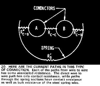
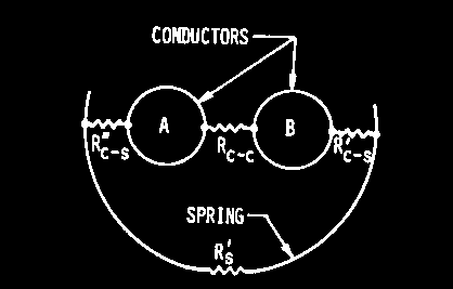
20. Here are the current paths in this type of connection. Each of the paths from wire to wire has some associated resistance. The direct wire to wire path has only contact resistance, while paths
through the spring sections have contact resistance as well as bulk resistance of the steel wire.
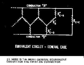
21. Here is the most general equivalent circuit for the twist-on connector
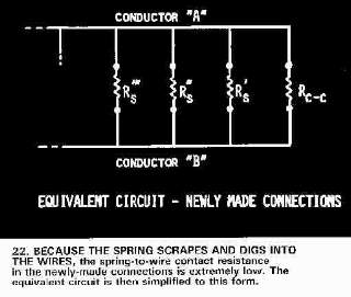
22. Because the spring scrapes and digs into the wires, the spring-to-wire contact resistance in the newly-made connections is extremely low. The equivalent circuit is then simplified to this form
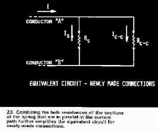
23. Combining the bulk resistance of the sections of the spring that are in parallel in the current path further simplifies the equivalent circuit for newly-made connections.
Current Flow in an Overheating Twist-On Connector
This article continues below with an explanation of common twist on connectors and copper pigtailing as an attempt at aluminum wiring repair.
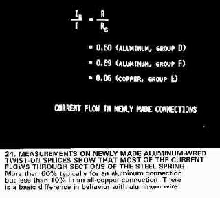
The key observation is that with this type of aluminum to copper wire splice, most of the current flows through the spring in the connector. In the design of twist-on wire connectors the purpose of the spring is to maintain tension on the spliced wires, not to conduct electricity itself.
24. Measurements on newly made aluminum-wired twist-on splices show that most of the current flows through sections of the steel spring.
More than 60% typically for an aluminum connection, but less than 10% for an all-copper connection. There is a basic difference in behavior with aluminum wire.
Connection Deterioration in a Twist On Connector Used for Aluminum Wiring Repair
This article continues with the explanation of why twist-on connectors overheat and lead to failures when used for copper to aluminum pigtailing as an attempt at aluminum wiring repair. The observation explained here is that with this type of aluminum to copper wire splice, resistance increases between the copper and aluminum wires, leading to overheating of the connection and the twist-on the connector.
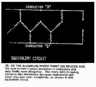
25. As the aluminum-wired twist-on splices age, the wire-to-wire contact increases in resistance and may finally open altogether. The many wire-to-spring contacts also deteriorate (increase
resistance) and some may also open completely, as shown in this equivalent circuit.
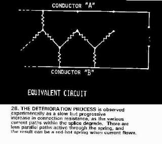
26. The deterioration process is observed experimentally as a slow but progressive increase in resistance, as the various current paths within the splice degrade. There are less parallel paths active
through the spring, and the result can be a red-hot spring when current flows.
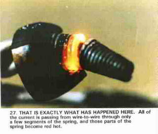
27. That is exactly what has happened here. All of the current is passing through only a few segments of the spring and those parts of the spring become red hot.
Text from attachment occurs here:
The CPSC Recommendation against the use of twist-on connectors for aluminum wire is soundly based. There is no reason to believe that the Ideal #65 connector, recently UL listed for
aluminum-to-copper combinations, overcomes the fundamental deficiencies of this type of connection for applications with aluminum wire.
Page Down to See Rest of Text
The Ideal #65 connector has a zinc-plated steel spring. A combination known to be bad in contact with aluminum. Containing a free-burning oxide inhibitor grease, and having a free-burning thermoplastic shell, the connector can ignite readily if failures of the types shown here occur.
The only justification given for marketing this connector as suitable for aluminum wiring is that it has passed the test requirements of UL486C.
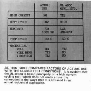
That the tests of UL486C are insufficient can be understood by considering the following table.[Table below.]
Table of UL-486C Electrical Connector Standards: comparing actual field-use with test conditions
Why the UL-486-C UL High-Current Cycle test is inadequate
28. This table compares factors of actual use with the UL486C test conditions. It is evident that the UL listing is based principally on a high current cycling test, which does not really stress the
connection in ways that it is stressed in an actual residential application.
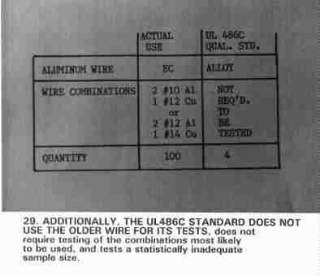
29. Additionally, the UL486C standard does not use the older wire for its tests, does not require testing of the combinations most likely to be used, and tests a statis
...
Continue reading at ALUMINUM WIRING SPECIAL CONNECTOR FAILURES or select a topic from the closely-related articles below, or see the complete ARTICLE INDEX.
Or see these
Recommended Articles
- ALUMINUM WIRING IDENTIFICATION
- ALUMINUM WIRING REPAIR METHODS
- ALUMINUM WIRING REPAIR ELECTRICIANS
- ALUMINUM WIRING REPAIR METHODS - CPSC Meeting 9/28/95
- COPPER PIGTAILING for ALUMINUM WIRE
- COPPER PIGTAILING FAILURES in ALUMINUM WIRING
- ALUMINUM WIRING FIELD FAILURES
- ALUMINUM WIRE to WIRE CONTACT
- ALUMINUM WIRING EQUIVALENT CIRCUITS
- ALUMINUM WIRING CONNECTOR CURRENT FLOW
- ALUMINUM WIRING CONNECTOR DETERIORATION
- ALUMINUM WIRING CONNECTOR UL TEST INADEQUATE
- ALUMINUM WIRING SPECIAL CONNECTOR FAILURES
- AMP TYCO COPALUM CONECTORS
- SCOTCHLOK 3M REPAIR CONNECTORS
- ALUMINUM WIRING REPAIR SPECIAL CONCERNS
- ALUMINUM WIRING REPAIRS NOT-RECOMMENDED
- REDUCE THE AL WIRE RISK: DETAILS
Suggested citation for this web page
ALUMINUM WIRING EQUIVALENT CIRCUITS at InspectApedia.com - online encyclopedia of building & environmental inspection, testing, diagnosis, repair, & problem prevention advice.
Or see this
INDEX to RELATED ARTICLES: ARTICLE INDEX to ELECTRICAL INSPECTION & TESTING
Or use the SEARCH BOX found below to Ask a Question or Search InspectApedia
Ask a Question or Search InspectApedia
Questions & answers or comments about the failure mechanism in and test standards for connectors used to repair aluminum electrical wiring.
Try the search box just below, or if you prefer, post a question or comment in the Comments box below and we will respond promptly.
Search the InspectApedia website
Note: appearance of your Comment below may be delayed: if your comment contains an image, photograph, web link, or text that looks to the software as if it might be a web link, your posting will appear after it has been approved by a moderator. Apologies for the delay.
Only one image can be added per comment but you can post as many comments, and therefore images, as you like.
You will not receive a notification when a response to your question has been posted.
Please bookmark this page to make it easy for you to check back for our response.
IF above you see "Comment Form is loading comments..." then COMMENT BOX - countable.ca / bawkbox.com IS NOT WORKING.
In any case you are welcome to send an email directly to us at InspectApedia.com at editor@inspectApedia.com
We'll reply to you directly. Please help us help you by noting, in your email, the URL of the InspectApedia page where you wanted to comment.
Citations & References
In addition to any citations in the article above, a full list is available on request.
- [1]AlumiConn [Website: AlCopStore.com ] ™ AlCopStore.com
223 Salt Lick Road, #279,
St. Peters, MO 63376
Tel: 866-826-2256, Fax: 636-754-0500, Email Sales: pking@AlCopStore.com, Email General Inquiry: info@AlCopStore.com - [2] "Repairing Aluminum Wiring," [As updated 2011] U.S. Consumer Product Safety Commission Publication available online
- [3] "Record of Commission Action, Commissioners Voting by Ballot", CPSC Publication No. 516, Repairing Aluminum Wiring (original version op.cit.), (Briefing package dated March 15, 2011), Quoting:
The Commission voted unanimously (5-0)·to approve republication of CPSC Publication No. 516, Repairing Aluminum Wiring, with the explicit recognition that the COPALUM and AlumiConn connectors currently are the only products that meet the agency's standards to prevent aluminum wire fire hazards
Copy on file as /aluminum/Pub516_Alumi_Conn.pdf - [4] Dr. Jess Aronstein, protune@aol.com is a research consultant and an electrical engineer in Schenectady, NY. Dr. Aronstein provides forensic engineering services and independent laboratory testing for various agencies. Dr. Aronstein has published widely on and has designed and conducted tests on aluminum wiring failures, Federal Pacific Stab-Lok electrical equipment, and numerous electrical products and hazards. See ALUMINUM WIRING BIBLIOGRAPHY and See FPE HAZARD ARTICLES, STUDIES for examples.
- [5] "The Influence of Corrosion Inhibitor and Surface Abrasion on the Failure of Aluminum-Wired Twist-on Connections", Aronstein, J.; Campbell, W., Components, Hybrids, and Manufacturing Technology, IEEE Transactions on Volume 7, Issue 1, Mar 1984 Page(s): 20 - 24
- [6] Thanks to reader Thomas Kremer for suggesting clarification to this topic 08/09
- [7] Personal communication, Email, P. King to D Friedman, 3/10/2012 [copy on file AlumiConn_PK120310.pdf].
- Our recommended books about building & mechanical systems design, inspection, problem diagnosis, and repair, and about indoor environment and IAQ testing, diagnosis, and cleanup are at the InspectAPedia Bookstore. Also see our Book Reviews - InspectAPedia.
- ALUMINUM WIRE REPAIR METHODS to reduce risk in buildings with Aluminum Electrical Wiring - Overview of Acceptable Repair Practices (in the document you are presently viewing)
- Reducing the Fire Hazards in Aluminum-Wired Homes, Jess Aronstein, Ph.D., This document answers most technical questions about the hazards and remedies of aluminum electrical wiring. Some of the sections of this very thorough document are listed below:
- Fire Hazards With Aluminum to Copper Twist-on Connectors & Acceptable Aluminum Wiring Repair Practices Color Photos, Current Issues. 9/28/95 CPSC Meeting Minutes
- REPAIRING ALUMINUM WIRING, US CPSC Pub. No. 516 U.S. Consumer Product Safety Commission Publication available online
- Directory of Home Inspectors accessible via Internet
- In addition to citations & references found in this article, see the research citations given at the end of the related articles found at our suggested
CONTINUE READING or RECOMMENDED ARTICLES.
- Carson, Dunlop & Associates Ltd., 120 Carlton Street Suite 407, Toronto ON M5A 4K2. Tel: (416) 964-9415 1-800-268-7070 Email: info@carsondunlop.com. Alan Carson is a past president of ASHI, the American Society of Home Inspectors.
Thanks to Alan Carson and Bob Dunlop, for permission for InspectAPedia to use text excerpts from The HOME REFERENCE BOOK - the Encyclopedia of Homes and to use illustrations from The ILLUSTRATED HOME .
Carson Dunlop Associates provides extensive home inspection education and report writing material. In gratitude we provide links to tsome Carson Dunlop Associates products and services.


