
InspectAPedia® FREE Encyclopedia of Building & Environmental Construction, Diagnosis, Maintenance & Repair |
Question? Just ask us! InspectAPedia
|
 Sand Bed Filter Septic System Design, Inspection, Maintenance

- POST a QUESTION or COMMENT about recirculating sand bed filter systems: design, installation, diagnosis, repair, maintenance
Sandbed septic system design & constructin guide:
Intermittent, Recirculating or Single Pass Sand Filter Septic Systems: this document discusses the design, inspection, repair, and installation of sand beds, septic filter beds, intermittent sand filters, or recirculating sand filters for wastewater or septic effluent treatment and disposal.
Here we discuss the design & Maintenance of Intermittent and Recirculating Sand Filters & Sand Beds for Wastewater or Septic Effluent Disposal Systems as Components of Alternative Septic Systems - for wet sites, steep sites, rocky sites, limited space, and other difficult site conditions. Sand bed septic system design guidelines from State Sanitary Code & the US EPA.
Illustration above: U.S. EPA recirculating sand filter system, cited & discussed in detail below.
InspectAPedia tolerates no conflicts of interest. We have no relationship with advertisers, products, or services discussed at this website.
- Daniel Friedman, Publisher/Editor/Author - See WHO ARE WE?
How a Sandbed Septic Wastewater Treatment System Works

As we explain at AEROBIC SEPTIC SYSTEMS, ATUs and excerpt here: Aerobic sandfilter treatment systems filter ATUs have the same treatment level as the type 1 aerobic systems above, but work by filtering effluent through a sand layer to provide natural aeration rather than using a compressor or air pump inside of the treatment tank.
[Click to enlarge any image]
Treatment of wastewater in the sand bed occurs through natural (no pump) aeration and biological oxidation through the action of aerobic bacteria and nitrifying organisms.
The effluent discharged from a properly working ATU is sufficiently sanitary that it should be able to be used for surface irrigation within the site.
Below we describe various types of sandbed or filterbed septic systems. We summarize each sandbed septic type and then give in-depth detail about how these units function and what are the design specifications for each.
Intermittent Sand Bed Filter Bed Septic Systems
In an intermittent sand filter septic system,, wastewater effluent from the septic tank is intermittently distributed over the surface of a specially prepared bed of sand placed atop the existing soil surface.
Septic effluent which has passed through the sand is collected by additional pipes at the bottom of the sand bed.
The septic bed sand is not visible as it's covered by topsoil.
You can read additional detail about intermittent sand filter bed septic designs from New York State Sanitary Code (below) and complete detail is in the article below, at Intermittent Sand FIlter Septics from the US EPA Wastewater Design Manual.
Recirculating Sand Bed Filter Septic Systems

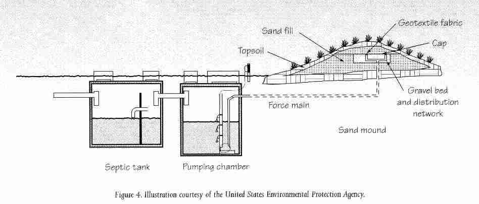
Alternatively, a recirculating sand filter system is shown in this sketch. Recirculating sand filters spray or discharge septic effluent over a bed of sand. The wastewater is filtered by the sand and treated by microbes that form there.
Effluent is collected at the bottom of the sand filter and pumped or recirculated (usually through a holding tank) back to the top of the sand filter for repeat processing several times before final discharge to a final treatment and effluent disposal system.
Some sand bed septic systems also make use of effluent disinfection as a final step before effluent is discharged to the environment.
You can read additional detail about recirculating sand filter bed septic designs below, from the US EPA Wastewater Design Manual
Intermittent Sand Filter Septic Systems Design Criteria
The following is from: New York Appendix 75-A.9 Alternative Septic System Designs section 9.d Intermittent Sand Filter Bed Septic Systems. Section 75-A.9 Alternative Septic Systems - (d)
Title: Appendix 75-A.9 - Alternative Septic Systems [Regulation and System Design Criteria for Raised Septic Systems,
Septic Mound Systems, Intermittent Sand Filter Bed Systems, Evaporation-Transpiration Septic Systems,
Evaporation-Transpiration Absorption Septic Systems, and Other Alternative Septic Systems]
Effective Date: 12/01/1990
Also see Lesikar, Bruce, SAND FILTER SEPTIC SYSTEMS, [PDF] (1999) Texas Agricultural Extension Service, Texas A&M University, retrieved 2018/09/01, original source: https://www.h-gac.com/community/water/ossf/OSSF-Treatment-Systems_Sand-Filter.pdf
(1) Sand Bed Septic Systems - General
In a sand filter septic system, the septic tank or aerobic unit effluent is intermittently spread across the surface of a bed of sand through a network of distribution lines. Collector pipes beneath the filter collect treated effluent after it has passed through the sand.
(2) Site Requirements for Sand Filter Bed Septic Systems
(i) All horizontal separation distances shown in Table 2 must be met and the minimum required vertical separation to groundwater must be met from the bottom of the collector pipes.
(ii) An environmental assessment determines that the development of the site with a sand filter is consistent with the overall development of the area and will cause no adverse environmental impacts.
(3) Design Criteria for Sand Filter Bed Septic Systems
The sketch above (US EPA Onsite Wastewater Treatment Systems Manual) is of an intermittent-dosing sand bed system. Recirculating sand filters spray or discharge septic effluent over a bed of sand where it is filtered, treated, and re-circulated through the filter several times before final discharge.
(i) Septic tanks installed before a sand filter shall have dual compartments
or two tanks in series. The use of a gas baffle on the outlet
is strongly recommended.
(Photo of this sand mound system is courtesy EPA).
(ii) The direct discharge of sand filter effluent to the ground surface or to a body of water shall not be approved
by the Department of Health or a local health department acting as its agent.
(iii) Distributor lines
shall be placed at three foot center lines as level as possible.
(iv) Collector pipes
shall be centered between distribution lines at a slope of 1/16 to 1/8 inch per foot.
(v) Effluent shall be distributed to the sand filter by means of pressure distribution or siphon dosing.
Pressure distribution lines shall be a minimum of 1.5 inches and a maximum of three inches in diameter. If siphon dosing is allowed, the distributor pipe(s) shall have a diameter of three to four inches.
(vi) The distribution system shall be designed to dose the filter at least three times daily
based upon the design flow rates with each dose.
(vii) The sand media shall have an effective grain size of 0.25 to 1.0 mm.
If nitrification is not required by the local health department, the effective grain size shall be in the range of 0.5 to 1.00 mm. All sand shall pass a 1/4 inch sieve.
(viii) The uniformity coefficient of the sand
shall not exceed 4.0.
(ix) The maximum allowed daily sand loading rate shall be 1.15 gal/day/sq. ft.
(x) Effluent from the collector pipes shall be discharged to an absorption bed
located below the original ground level or a mound that is built up above the original ground surface. The size of the bed/mound shall be based upon the estimated quantity of effluent reaching the collector pipe and an application rate of 1.2 gal/day/sq. ft. regardless of the underlying soil percolation.
The fill material for the bed/mound shall consist of medium sand with a percolation rate, tested at the borrow pit, not faster than five minutes per inch. All minimum vertical and horizontal separation distances shall be maintained as described in Section 75-A.4.
(4) Construction of Sand Bed Septic Systems
(i) After excavation, the collector pipe shall be placed in 3/4 inches to 1 1/2 inches size aggregate.
(ii) There shall be a minimum of four inches of this aggregate beneath the entire system above the collectors.
(iii) A three inch layer of crushed stone or clean gravel with a size of 1/8 inches to 1/4 inches is carefully placed on top of the aggregate.
(iv) A minimum of 24 inches of the approved sand is placed above the crushed stone or gravel.
(v) The distributor pipes are placed in a layer of aggregate that provides a minimum of four inches across the entire surface of the filter and at least two inches above and below the distributor pipes.
(vi) A permeable geotextile, two inches of hay or straw, or untreated building paper is placed over the entire bed area to prevent the infiltration of fines into the filter.
(vii) The entire surface of the filter shall be covered with six to 12 inches of topsoil, mounded to enhance the runoff of rainwater from the system and seeded to grass.
(viii) The bed/mound following the filter shall be covered with 12 inches of topsoil and seeded to grass.
Intermittent Sand/Media Filters - US EPA Design Notes
Onsite Wastewater Treatment Systems Technology Fact Sheet 10 - EPA 625/R-00/008
Description of Intermittent Sand/Media Filter Septic System Designs
The term intermittent sand filter (ISF) is used to describe a variety of packed-bed filters of sand or other granular materials available on the market. Sand filters provide advanced secondary treatment of settled wastewater or septic tank effluent.
They consist of a lined (e.g., impervious PVC liner on sand bedding) excavation or structure filled with uniform washed sand that is placed over an underdrain system (see figure 1). The wastewater is dosed onto the surface of the sand through a distribution network and allowed to percolate through the sand to the underdrain system.
The underdrain system collects the filter effluent for further processing or discharge.
Figure 1. Generic, open intermittent sand filter septic system
[Click to enlarge any image or to see original gif]
Sand filters are aerobic, fixed-film bioreactors. Other treatment mechanisms that occur in sand filters include physical processes, such as straining and sedimentation, that remove suspended solids within the pores of the media.
Also, chemical adsorption of pollutants onto media surfaces plays a finite role in the removal of some chemical constituents (e.g., phosphorus). Bioslimes from the growth of microorganisms develop as films on the sand particle surfaces.
The microorganisms in the slimes absorb soluble and colloidal waste materials in the wastewater as it percolates over the sand surfaces. The adsorbed materials are incorporated into a new cell mass or degraded under aerobic conditions to carbon dioxide and water.
Most biochemical treatment occurs within approximately 6 inches of the filter surface. As the wastewater percolates through this layer, suspended solids and carbonaceous biochemical oxygen demand (BOD) are removed. Most suspended solids are strained out at the filter surface.
The BOD is nearly completely removed if the wastewater retention time in the sand media is sufficiently long for the microorganisms to absorb wastewater constituents.
With depleting carbonaceous BOD in the percolating wastewater, nitrifying microorganisms are able to thrive deeper in the surface layer where nitrification will readily occur.
Chemical adsorption can occur throughout the media bed. Adsorption sites in the media are usually limited, however. The capacity of the media to retain ions depends on the target constituent, the pH, and the mineralogy of the media. Phosphorous is one element of concern in wastewater that can be removed in this manner, but the number of available adsorption sites is limited by the characteristics of the media.
The basic components of intermittent sand filters include a dosing tank, pump and controls (or siphon), distribution network, and the filter bed with an underdrain system (see figure 1).
The wastewater is intermittently dosed from the dosing tank onto the filter through the distribution network. From there, it percolates through the sand media to the underdrain and is discharged. On-demand dosing is usually used, but timed dosing is becoming common.
There are a large number of variations in ISF designs. For example, there are different means of distribution, underdrain designs, housing schemes and, most notably, media choices. Many types of media are used in single-pass filters. Washed, graded sand is the most common.
Other granular media used include gravel, crushed glass, and bottom ash from coal-fired power plants. Foam chips (polystyrene), peat, and coarse-fiber synthetic textile materials have also been used. These media are generally restricted to proprietary units. System manufacturers should be contacted for application and design using these materials.
There are also related single-pass designs, which are not covered in this fact sheet. These include lateral flow designs and upflow-wicking concepts, both of which use physical removal concepts closer to the concepts described in the fact sheet on anaerobic upflow filters and vegetated submerged beds.
These processes are not discussed herein but may exhibit some pollutant removal mechanisms that are described here. Simple gravity-fed, buried sand filters are not discussed because their performance history is unsatisfactory.
Applications for Intermittent Sand/Media Filter (ISF) Septic System Designs
Sand filters can be used for a broad range of applications, including single-family residences, large commercial establishments, and small communities. Sand filters are frequently used to pretreat septic tank effluent prior to subsurface infiltration onsite where the soil has insufficient unsaturated depth above ground water or bedrock to achieve adequate treatment.
They are also used to meet water quality requirements (with the possible exception of fecal coliform removal) before direct discharge to a surface water. Sand filters are used primarily to treat domestic wastewater, but they have been used successfully in treatment trains to treat wastewaters high in organic materials such as those from restaurants and supermarkets.
Single-pass ISF filters are most frequently used for smaller applications and sites where nitrogen removal is not required.
However, they can be combined with anaerobic processes to reduce nitrogen significantly. Many studies have shown that ISF-treated onsite wastewaters can reduce clogging of the infiltrative surface by many times when compared with septic-tank effluents.
However, be careful to evaluate the overall loading of pollutants and pathogens to the underlying aquifer and nearby surface waters before considering significant SWIS sizing reductions.
Design of Intermittent Sand/Media Filter Septic System Designs
Above: The US EPA's illustration of a recirculating sand filter system that can be constructed above ground or below ground level. - 2023/12/31, original source: US EPA, epa.gov/septic/types-septic-systems#sand from whom we quote:
Sand filter systems can be constructed above or below ground. Effluent flows from the septic tank to a pump chamber. It is then pumped to the sand filter. The sand filter is often PVC-lined or a concrete box filled with a sand material.
Effluent is pumped under low pressure through the pipes at the top of the filter. The effluent leaves the pipes and is treated as it filters through the sand. The treated wastewater is then discharged to the drainfield.
Sand filters provide a high level of treatment for nutrients and are good for sites with high water tables or that are close to water bodies, but they are more expensive than a conventional septic system.
ISF filter design starts with the selected media. The media characteristics determine the necessary filter area, dose volumes, and dosing frequency. Availability of media for a specific application should be determined before completing the detailed design. Typical specifications, mass loadings, and media depths are presented in table 1. The sand or gravel selected should be durable with rounded grains.
Only washed material should be used. Fine particles passing the U.S. No. 200 sieve (less than 0.074 mm) should be limited to less than 3 percent by weight. Other granular media that have been used are bottom ash, expanded clay, expanded shale, and crushed glass.
These media should remove BOD and TSS similar to sand and gravel for similar effective sizes, uniformity, and grain shape. Newer commercial media such as textile materials have had limited testing, but based on early testing should be expected to perform as well as the above types.
Table 1. Specifications, mass loadings, and depth for single-pass intermittent sand filters
| Design parameter | Typical design value |
| Material | Durable, washed sand/gravel with rounded grains |
| Specifications Effective size Sand Gravel Uniformity coefficient Percent fines (passing 200 sieve or <0.074 mm) |
0.25 - 1.00 mm N/A <4 [ 3 |
| Depth | 2 to 3 ft |
| Mass loadings Hydraulic loadinga Sand Gravel Organic loadingb Sand Gravel |
1 - 2 gpd/ft2 N/A 5 lb BOD5/1,000 ft2-d N/A |
| Underdrains Slope Size |
0 - 0.1% 3 - 4 in. dia. |
| Dosing Frequency |
12 - 24 times per day |
| Dosing tank Volume |
0.5 - 1.5 times design daily flow |
Notes to the table above:
a 1 gpd/ft2 = 4 cm/day = 0.04 m3/m2 per day
b 1 lb BOD/1000 ft2 per day = 0.00455 kg/m2 per day
Traditionally, sand filters have been designed based on hydraulic loadings. However, since these filters are primarily aerobic biological treatment units, it is more appropriate that they be designed based on organic loadings. Unfortunately, insufficient data exist to establish well-defined organic loading rates.
Experience presently suggests that BOD5 loadings on sand media should not exceed about 5 lb/1,000 ft3 per day (0.024 kg/m2 per day) where the effective size is near 1.0 mm and the dosing rate is at least 12 times per day.
Higher hydraulic and organic loadings have been described in several studies, but the long-term viability of the systems loaded at those higher organic loads has not yet been fully verified. The values in the table are thus considered conservative and may be subject to increases as more quality-assured data become available.
Dosing volume and frequency have been shown to be the critical design variables.
Small dose volumes are preferred because the flow through the porous media will occur under unsaturated conditions with higher moisture tensions. Better wastewater media contact and longer residence times occur under these conditions. Smaller dose volumes are achieved by increasing the number of doses per day.
It has been suggested that each dose should be <0.5 cm (based on media surface perpendicular to infiltration direction) to fully nitrify the effluent in an ISF. This would limit maximum daily hydraulic loading to 12 cm/d, or 3 gpd/ft2, if the maximum frequency of daily dosing is accepted as 24 (or hourly) as supported by the literature. Media characteristics can limit the number of doses possible.
Reaeration of the media must occur between doses. As the effective size of the media decreases, the time for drainage and reaeration of the media increases.
Distribution network characteristics will also limit the number of doses possible.
The primary characteristics are the volume, pressure, orifice sizes, and spacing. To achieve uniform distribution over the filter surface, minimum dose volumes are necessary and can vary with the distribution method selected. Therefore, if the dose volume dictated by the distribution network design is too high, the network should be redesigned.
Since the dose volume is a critical operating parameter, the method of distribution and design of the distribution system should be considered carefully. Distribution methods used include rigid pipe pressure networks with orifices or spray nozzles, drip distribution, and surface flooding, which is no longer recommended for small ISFs (see chapter 4). Rigid pipe pressure networks are the most commonly used method.
Both orifices and spray nozzles are used. The use of spray nozzles is usually limited to recirculating filters because nozzle fouling from suspended solids is less likely than with undiluted septic tank effluent.
Since the minimum dose volume required to achieve uniform distribution is five times the rigid pipe volume, the filter can be divided into multiple cells that are loaded individually so the distribution networks can be smaller to reduce the dose volume needed for uniform distribution.
Optimum designs minimize the dose each time the system is dosed. Drip distribution is being used increasingly because the minimum dose volumes are much less than the volumes of rigid pipe networks.
Figure 2. ISF constructed in a mound with direct subsurface infiltration
[Click to enlarge any image]
Source: Converse and Tyler, 1998. (US EPA Publication)
The underdrain system is placed on the floor of the tank or lined excavation. Ends of the underdrains should be brought to the surface of the filter and fitted with cleanouts that can be used to clean the biofilms underdrain, if necessary. The underdrain outlet is cut in the basin wall such that the drain invert is at the floor elevation and the filter can be completely drained.
The underdrain outlet invert elevation must be sufficiently above the recirculation tank inlet to accommodate a minimum of 0.1 percent slope on the return line and any elevation losses through the flow splitting device.
The underdrain (usually 1.25- to 2.0-inch PVC, class 200 [minimum]) is covered with washed, durable gravel to provide a porous medium through which the filtrate can flow to the underdrain system. The gravel should be sized to prevent the filter medium from mixing into the gravel, or a layer of 1/4- to 3/8-inch-diameter washed pea gravel should be placed over the washed underdrain gravel before the filter medium is added.
The filter basin can be a lined excavation or fabricated tank. For single-home systems, prefabricated concrete tanks are commonly used. Many single-home filters and most large filters are constructed within lined excavations. Typical liner materials are polyvinyl chloride and polypropylene.
A liner thickness of 30 mil can withstand reasonable construction activities yet be relatively easy to work with. A sand layer should be placed below the liner to protect it from being punctured if the floor and walls of the excavation are stony.
The walls of the excavation should be brought above the final grade to prevent entry of surface water.
Filters can be covered or buried. It is often necessary to provide a cover for the filter surface because the surface of a fine medium (e.g., sand) exposed to sunlight can be fouled with algae. Also, there may be concerns about odors, cold weather impacts, precipitation, leaf and debris accumulation, and snowmelt.
In addition, the cover must provide ample fresh air venting. Reaeration of the filter medium primarily occurs from the filter surface.
The lower 20 percent of the medium's depth maintains a high moisture content. At the bottom, the medium is near or at saturation, which is a barrier to air flow and venting from the underdrain system. The gravel surrounding the distribution piping must be vented to the surface to provide a fresh air flow.
ISF filters open to the surface are built with roofs or removable covers or are merely shaded. Roofs provide cold weather protection and shed precipitation, debris, and snowmelt that would otherwise enter the system.
Performance of Intermittent Sand/Media Filter Septic System Designs
Treatment field performance of single-pass intermittent sand filters is presented in table 2. Typical effluent concentrations for these single-family wastewater treatment systems are less than 5 mg/L and less than 10 mg/L for BOD and TSS, respectively.
Effluent is nearly completely nitrified but some variability can be expected in nitrogen removal capability. Controlled studies generally find typical nitrogen removals of 18 to 33 percent with an ISF. Fecal coliform removal ranges from 2 to 4 logs (99 to 99.99 percent).
ISF fecal coliform removal is a function of hydraulic loading, with reduced removals as the loading rate increases above 1 gpm/ft2 (Emerick et al., 1997). Effluent suspended solids from sand filters are typically low. The media retains the solids. Most organic solids are digested by the media over time.
Table 2. Single-pass intermittent sand filter septic system performance
| Reference | BOD (mg/L) | BOD (mg/L) | BOD (mg/L) | BOD (mg/L) | BOD (mg/L) | |||||
| Influ. | Efflu. | Influ. | Efflu. | Influ. | Efflu. | Influ. | Efflu. | Influ. | Efflu. | |
| (% Removal) | (% Removal) | (% Removal) | (% Removal) | (% Removal) | ||||||
| Cagle and Johnson, 1994a (California) | 160 | 2 | 73 | 16 | 61.8 | 5.9 | 61.8 | 37.4 | 1.14E+05 | 1.11E+02 |
(98.75%) |
(78.08%) | (90.45%) | (39.48%) | (99.90%) | ||||||
| Effert et al., 1985b (Ohio) | 127 | 4 | 53 | 17 | - | - | 41.5 | 37.5 | 2.19E+05 | 1.60E+03 |
| (96.85%) | (67.92%) | - | (9.64%) | (99.27%) | ||||||
| Ronayne et al., 1982c (Oregon) | 217 | 3 | 146 | 10 | 57.1 | 1.7 | 57.5 | 30.3 | 2.60E+05 | 4.07E+02 |
| (98.62%) | (93.15%) | (97.02%) | (47.30%) | (99.84%) | ||||||
| Sievers, 1998d (California) | 297 | 3 | 44 | 3 | 37 | 0.5 | 37.1 | 27.5 | 4.56E+05 | 7.30E+01 |
| (98.99%) | (93.18%) | (98.65%) | (25.88%) | (99.98%) | ||||||
Notes to the table above
a Sand media: es=0.25 - 0.65 mm; uc=3 - 4. Design hydraulic loadings = 1.2 gpd/ft2 based on 150 gpd/bedroom. Actual flows not measured.
b Sand media: es=0.4 mm; uc=2.5. Average loadings=0.4 gpd/ft2/0.42 lb BOD/1,000 ft2. Doses per day=3.3.
c Sand media: es=0.14 - 0.30 mm; uc=1.5 - 4.0. Average loadings=0.33 gpd/ft2/0.6 - 1.27 lb BOD/1000ft2 per day.
d Sand media: not reported; uc=3 - 4. Design hydraulic loadings=1 gpd/ft2. Daily flows not reported.
Management needs of Intermittent Sand/Media Filter Septic System Designs
Construction of ISF units usually involves excavation, forming/framing, liner placement with supporting sand layers, and plumbing. ISF units should never be placed in surface depressions without thoroughly sealing against prolonged inundation and drainage configurations that prevent stormwater entry.
In all cases, units must be watertight with sealed entries and exits for piping. Filter fabric should not be used at any location through which the filtrate would flow. Media delivered to the site should be tested against design-sizing specifications. Excess (3 percent or greater) fines are one of the greatest concerns of the construction inspector.
The operation and maintenance requirements of packed bed filters are few and simple. As with all treatment systems, flow monitoring should be conducted to identify excessive flows and check dose volumes and dosing rates.
If the flows are excessive, the source of the flows should be identified and corrective measures taken. Reduced dose volumes or dosing rates suggest that the distribution network is plugged or the pump is not performing properly. The distribution network should be flushed annually (or more often, as necessary) using the manual flushing device.
Also, the dosing pump should be recalibrated at least annually.
The filter surface should not pond if the filter is designed properly and the wastewater characteristics do not change significantly. If standby cells are not available for regular resting and the surface is not covered with pea gravel, the surface can be raked to break up any material clogging the filter surface.
Reducing the dose volume and increasing the dosing frequency may help to increase the reaeration potential and reduce clogging of the media.
If the ponding problem persists, however, removal of the top layer or complete replacement of the media may be necessary. Before replacing the media, monitor wastewater flows and concentrations to determine if they are the cause of the problem.
Problem sources should be identified and addressed before repairs are effected. Premature clogging is often traceable to excess TSS and BOD loading or to fines in the media. Where the problem develops naturally over time and standby cells are available, resting may be used to supplement the raking and/or surface skimming steps.
Free-access ISFs should be checked regularly (at least every 3 to 4 months), to prevent surface problems. Periodic raking and resting is recommended to maintain percolation and prevent ponding.
Scraping off the top layer (e.g., 1 inch) of sand helps to prevent clogging. Intervals between scraping vary from a minimum of 3 months up to greater than 1 year. Removed surface layers need not be replaced until the total filter depth falls below 18 inches. If new filter material is not readily available, it may be cost-effective to clean and reuse the old filter material. Resting is considered the best rehabilitation approach due to possible clogging contributions from raking/scraping.
ISFs have low energy requirements compared with other systems offering comparable effluent quality. Free-access ISFs using pumped dosing would require approximately 0.3 to 0.4 kWh/day.
Risk management issues for Intermittent Sand/Media Filter Septic System Designs
ISF filters are simple in design and relatively passive to operate because the fixed-film process is very stable and few mechanical components are used. High flow variations after equalization in a septic tank are not a problem because the residual peaks and valleys are absorbed in the pressurization tank or in the last compartment of the preceding septic tank.
Although ISFs have biological properties, the impact of toxic loading shocks are not well documented.
Free-access ISFs are often installed with removable covers to regulate temperatures in cold climates and to reduce odors. Space of 12 to 24 inches (30 to 61 cm) should be allotted between the sand surface and the installed cover (EPA, 1980). Odors from free-access filters treating septic tank effluent may warrant installation away from dwellings, especially if spray nozzles are used in distribution.
Power outages will impact ISF systems if these systems are uniformly dosed with pumps. During the power outage, all wastewater generated will accumulate in that dosing facility and septic tank, increasing the potential for odors.
Costs of Intermittent Sand/Media Filter Septic System Designs
Filter media is the most expensive component in ISF construction. Typically, filter media can be installed for $10 to $15 per square foot, depending primarily on the type of media and the contractor's experience with ISF construction.
Operation/maintenance costs include electricity for pumping/dosing, and 3 to 6 hours of semiskilled management visits per year cost about $150 to $200. The electricity is about $10 to $20 of that total.
Design Standards for Intermittent Sand/Media Filter Septic System Designs
- Anderson, D.L., R.L. Siegrist, and R.J. Otis. 1985. Technology Assessment of Intermittent Sand Filters. U.S. Environmental Protection Agency, Office of Research and Development and Office of Water, Washington, DC.
- Bauer, D.H., E.T. Conrad, and D.G. Sherman. 1979. Evaluations of Existing and Potential Technologies for Onsite Wastewater Treatment and Disposal. EPA/600/S2-81-178. U.S. Environmental Protection Agency, Office of Research and Development, Cincinnati, OH.
- Boller, M., A. Schwager, J. Eugster, and V. Mottier. 1993. Dynamic Behavior of Intermittent Buried Filters. In Small Wastewater Treatment Plants, ed., H. Odegaard, TAPIR, Trondheim, Norway.
- Cagle, W.A., and L.A. Johnson. 1994. On-site intermittent sand filter systems: a regulatory/scientific approach to their study in Placer County, California. In Proceedings of the Seventh Onsite Wastewater Treatment Symposium, American Society of Agricultural Engineers, St. Joseph, MI.
- Darby, J., G. Tchobanoglous, M. Asri Nor, and D. Maciolek. 1996. Small Flows Journal 2(31): 3-15.
- Effert, D., J. Morand, and M. Cashell. 1985. Field performance of three onsite effluent polishing units. In Proceedings of Fourth Onsite Wastewater Treatment Symposium, American Society of Agricultural Engineers, St. Joseph, MI.
- Emerick, R.W., R.M. Test, G. Tchobanoglkous, and J. Darby. 1997. Small Flows Journal 3(1):12-22.
- Florida, SEPTIC TANK & DRAINFIELD SIZE GUIDE [PDF], Florida DOH, retrieved 2022/08/05 original source: https://martin.floridahealth.gov/programs-and-services/environmental-health/onsite-sewage-disposal/_documents/Residencespage5.pdf
- Maryland SAND MOUND MANUAL 5th Ed. [PDF] State of Maryland
Department of the Environment
WaterManagementAdministration
Wastewater Permits Program
On-Site Systems Division, https://mde.maryland.gov/
Excerpt:
This manual provides information on site selection, design and construction of sand mound sewage disposal systems in Maryland.
The manual has been prepared for use in Department-sponsored training programs and applies to small residential systems with five bedrooms or less. Larger sand mound systems and systems receiving non-domestic sewage may require more detailed soil- hydrogeologic investigations, different sizing and design criteria and additional pretreatment.
Specific site evaluation, design, installation and maintenance criteria which may not be discussed in this manual are required if any Sand Mound system is to be considered a Class IV BAT. Refer to the most current version of the MDE document called “ BAT CLASS IV: SAND MOUNDS” for the specific requirements. - Minnesota PCA, RECIRCULATING AND FILTER, Advance Designs for Subsurface
Sewage Treatment Systems
Recommended Standards and
Guidance Document [PDF] (2013) Minnesota Pollution Control Agency, MPCA, Tel: 651-296-6300 or 800-657-3864, Email: info.pca@state.mn.us retrieved 2020/05/29 original source: pca.state.mn.us/sites/default/files/wq-wwists4-41.pdf
Note exerpt: This is a guidance document produced by the Minnesota Pollution Control Agency (MPCA) for the benefit of the general public and wastewater treatment professionals alike. It is in no way intended as a substitute for professional engineering consulting advice.
While the scenarios described in this document may appear to provide solutions for some situations, users of this guide are strongly recommended to seek the advice of their own consultants and wastewater treatment professionals who can assess the unique circumstances and address the specific concerns and needs of an individual project.
Application
Recirculating sand filters are fixed film wastewater treatment systems capable of producing a fairly high-quality, partially nitrified effluent. Recirculating sand filters are restricted to domestic strength wastewater applications.
Although recirculating sand filters do a good job at removing biochemical oxygen demand (BOD) and total suspended solids (TSS), they are not designed to reduce pathogens levels to below a specific limit (i.e. 10,000 cfu/100mL) unless disinfection is employed.
Recirculating sand filters are identified as one of the methods that qualify as a nitrogen reducing best management practice (BMP) as stipulated in 7080.2150 subpart 4 and 7081.0080 subpart 4 item D subitem (2). - Missouri DNR, RECIRCULATING MEDIA FILTER OPERATION & MAINTENANCE [PDF] (2018), Missouri Department of Natural Resources Water Protection Program - Public Drinking Water Branch P.O. Box 176 Jefferson City, MO 65102-0176 800-361-4827 or 573-751-5331 Web: dnr.mo.gov/env/wpp/, retrieved 2020/05/29 original source: dnr.mo.gov/pubs/pub2738.htm
- National Small Flows Clearinghouse. 1998. Intermittent Sand Filters. NSFC Fact Sheet for U.S. Environmenetal Protection Agency, Office of Water, Washington, DC.
- Orenco Systems, Inc. 1993. Cost Estimating for STEP Systems and Sand Filters. Orenco Systems, Inc., Roseburg, OR.
- PenState Extension, ELEVATED SAND MOUNDS FOR ON-LOT WASTEWATER TREATMENT [PDF] - retrieved 2022/08/05 original source: extension.psu.edu/elevated-sand-mounds-for-on-lot-wastewater-treatment
Excerpt:
To provide for on-lot treatment of wastewater in soils with between 20 and 60 inches of suitable soil available above the limiting zone, Pennsylvania has approved the use of elevated sand mounds.
The elevated sand mound, a constructed mound of sandy fill material placed on top of the 20 to 60 inches of natural or prevailing soil, has been shown to provide excellent treatment of effluent.
Elevated sand mounds are limited to sites having a maximum of 15 percent slopes. In addition, the Perc Rate must be between 3 and 180 minutes per inch. Proper siting, design, construction and maintenance of mound treatment systems are key to their proper functioning. - Rhode Island Department of Environmental Management (DEM). 2000. Sand Filter Guidance Document. Department of Environmental Management, Providence, RI.
- Ronayne, M.P., R.C. Paeth, and S.A. Wilson. 1982. Oregon On-site Experimental Systems Program. Final report to U.S. Environmental Protection Agency, Office of Research and Development, Cincinnati, OH.
- Sievers, D.M. 1998. Pressurized intermittent sand filter with shallow disposal field for a single residue in Boone County, MO. In Proceedings of the Eighth On-site Wastewater Treatment Symposium. American Society of Agricultural Engineers, St. Joseph, MI.
- Simons, A. P., and F. R. Magdoff. Disposal of Septic Tank Effluent in Mound and Sand Filter‐Trench Systems on a Clay Soil. Vol. 8, no. 4. American Society of Agronomy, Crop Science Society of America, and Soil Science Society of America, 1979.
Abstract:
Small‐scale mound systems and conventional sand filter‐trench systems for disposal of septic tank effluent were established on a clay soil. During a wet year (1976), major differences in soil moisture patterns were observed between the two systems.
Unsaturated flow of effluent occurred through the gravel/sand interface of the mound systems, although a slight pressure‐head buildup occurred at the bottom of the mound fill. Conventional sand filter‐trench systems were under water throughout most of the 1976 monitoring season.
However, when the dry conditions of 1977 allowed the water table to drop below 1.2 m, unsaturated conditions occurred below the gravel/sand interface of both the mound and sand filter systems.
Water tension patterns below the gravel/sand interface indicated development of the early stages of clogging (but not permanent ponding) in the mounds, while those within the sand filter‐trench system indicated the development of a restricting layer.
Rejuvenation of the mound infiltrative surface occurred during the warm and dry 1977 spring and early summer. Temperatures below the gravel/sand interface dropped to about −3°C during the winter in the mound systems, but stayed just above freezing in the sand filters. A lack of snow accumulation on top of the mounds probably allowed the subzero temperatures. - U.S. EPA, DECENTRALIZED SYSTEMS TECHNOLOGY FACT SHEET MOUND SYSTEMS [PDF] (1999) U.S. EPA,
Excerpts:
The mound system was originally developed in North Dakota in the late 1940s and called the NODAK disposal system.
Some soil types are unsuitable for conventional septic tank soil absorption systems.
As a result, alternative systems such as the mound system can be used to overcome certain soil and site conditions.
The mound design in predominate use today was modified from the NODAK design by the University of Wisconsin-Madison in the early 1970s.
Although there are now many different mound designs in use, this fact sheet will focus on the Wisconsin design.
The Wisconsin mound has been widely accepted and incorporated into many state regulations. The three principle components of a mound system are a pretreatment unit(s), dosing chamber and the elevated mound.
Recirculating Sand/Media Filters - US EPA Design Information
Onsite Wastewater Treatment Systems Technology Fact Sheet 11 EPA 625/R-00/008
Description of Recirculating Sand/Media Filter Septic Systems
Recirculating filters using sand, gravel, or other media provide advanced secondary treatment of settled wastewater or septic tank effluent. They consist of a lined (e.g., impervious PVC liner on sand bedding) excavation or structure filled with uniform washed sand that is placed over an underdrain system (see figure 1).
The wastewater is dosed onto the surface of the sand through a distribution network and allowed to percolate through the sand to the underdrain system. The underdrain system collects and recycles the filter effluent to the recirculation tank for further processing or discharge.
Figure 1. Typical recirculating sand filter septic system components
[Click to enlarge any image]
Recirculating sand filters (RSFs) are aerobic, fixed-film bioreactors. Other treatment mechanisms that occur in sand filters include physical processes, such as straining and sedimentation, that remove suspended solids within the pores of the media. Also, chemical sorption of pollutants onto media surfaces plays a finite role in the removal of some chemical (e.g., phosphorus) constituents.
Bioslimes from the growth of microorganisms develop as films on the sand particle surfaces.
The microorganisms in the slimes absorb soluble and colloidal waste materials in the wastewater as it percolates over the sand surfaces. The absorbed materials are incorporated into a new cell mass or degraded under aerobic conditions to carbon dioxide and water.
Most biochemical treatment occurs within approximately 6 inches of the filter surface. As the wastewater percolates through this layer, suspended solids and carbonaceous biochemical oxygen demand (BOD) are removed. Most suspended solids are strained out at the filter surface.
The BOD is nearly completely removed if the wastewater retention time in the sand media is sufficiently long for the microorganisms to absorb waste constituents. With depleting carbonaceous BOD in the percolating wastewater, nitrifying microorganisms are able to thrive deeper in the surface layer, where nitrification will readily occur.
Chemical adsorption can occur throughout the media bed. Adsorption sites in the media are usually limited, however. The capacity of the media to retain ions depends on the target constituent, the pH, and the mineralogy of the media. Phosphorus is one element of concern that can be removed from wastewater in this manner, but the number of available adsorption sites is limited by the characteristics of the media.
The basic components of recirculating filters include a recirculation/dosing tank, pump and controls, distribution network, filter bed with an underdrain system, and a return line. The return line or the underdrain must split the flow to recycle a portion of the filtrate to the recirculation/dosing tank.
A small volume of wastewater and filtrate is dosed to the filter surface on a timed cycle 1 to 3 times per hour. Recirculation ratios are typically between 3:1 and 5:1. In the recirculation tank, the returned aerobic filtrate mixes with the anaerobic septic tank effluent before being reapplied to the filter.
Recirculating filters must use a coarser media than single-pass filters because recirculation requires higher hydraulic loadings. Both coarse sand and fine gravel are used as filter media. Because of the high hydraulic conductivities of the coarse media, filtrate recirculation is used to provide the wastewater residence times in the media necessary to meet the treatment requirements.
Based on forward flow, daily hydraulic loadings are typically about 3 gpd/ft2 (2 to 5 gpd/ft2) when the filter media is coarse sand. Therefore, the corresponding combined daily filter hydraulic loading, including the recirculated flow, may be 6 to 25 gpd/ft2. Where gravel is used as the media, the daily hydraulic loadings are increased to as much as 10 to 15 gpd/ft2 with a combined daily loading of 30 to 75 gpd/ft2.
BOD and TSS removals are generally the same as those achieved by single-pass filters. Nearly complete ammonia removal by nitrification is also achieved. In addition, the mixing of the return filtrate anaerobic septic tank effluent removes approximately 50 percent of the total nitrogen. However, because of the greater hydraulic loadings and coarser media, fecal coliform removal is somewhat less than in single-pass filters.
Recirculating filters offer advantages over single-pass filters. Greater control of performance is possible because recirculation ratios can be changed to optimize treatment. The filter can be smaller because of the higher hydraulic loading. Recirculation also reduces odors because the influent wastewater (septic tank effluent) is diluted with return filtrate that is low in BOD and high in dissolved oxygen.
Many types of media are used in packed-bed filters.
Washed, graded sand was the most common, but pea gravel has generally replaced it in recent times. Other granular media used include crushed glass, garnet, anthracite, plastic, expanded clay, expanded shale, open-cell foam, extruded polystyrene, and bottom ash from coal-fired power plants.
Coarse-fiber synthetic textile materials are also used. These materials are generally restricted to proprietary units. Contact the system manufacturers for application and design using these materials.
Other modifications to the basic RSF design include the type of distribution system, the location and design of the recirculation tank, the means of flow splitting the filtrate between discharge and return flows, and enhancements to improve nitrogen removal. The last is addressed in Technology Fact Sheet 9 on nitrogen removal.
Applications for Recirculating Sand Filter Bed Septic System Components
Recirculating sand filters can be used for a broad range of applications, including single-family residences, large commercial establishments, and small communities. They are frequently used to pretreat wastewater prior to subsurface infiltration on sites where soil has insufficient unsaturated depth above ground water or bedrock to achieve adequate treatment.
They are also used to meet water quality requirements before direct discharge to a surface water.
RSFs are primarily used to treat domestic wastewater, but they have also been used successfully in treatment trains to treat wastewaters high in organic materials such as those from restaurants and supermarkets.
Single-pass filters are most frequently used for smaller applications and at sites where nitrogen removal is not required. Recirculating filters are used for both large and small flows and are frequently used where nitrogen removal is necessary. RSFs frequently replace aerobic package plants in many parts of the country because of their high reliability and lower O/M requirements.
Design for Recirculating Sand Filter Bed Septic System Components
Packed-bed filter design starts with the selected media. The media characteristics determine the necessary filter area, dose volumes, and dosing frequency. Availability of media for a specific application should be determined before completing the detailed design.
Typical specifications, mass loadings, and depths for sand and gravel media are presented in chapter 4. The sand or gravel selected should be durable with rounded grains. Only washed material should be used. Fine particles passing the U.S. No. 200 sieve (<0.074 mm) should be limited to less than 3 percent by weight. Other granular media are bottom ash, expanded clay, expanded shale, and crushed glass.
These media should perform similarly to sand and gravel for similar effective sizes, uniformity, and grain shape. Newer commercial media such as textile materials have had limited testing, but should be expected to perform as well as the above types.
Traditionally, media filters have been designed based on hydraulic loadings. However, since they are primarily aerobic biological treatment units, it is more appropriate that they be designed based on organic loadings. Unfortunately, insufficient data exist to establish well-defined organic loading rates.
Experience suggests that BOD5 loadings on sand media should not exceed about 5 lb/1000 ft2 per day (0.024 kg/m2 per day) where the effective size is approximately 1.0 mm and the dosing rate is at least 12 times per day. Higher loadings have been measured in short-term studies, but designers are cautioned about exceeding this loading rate until quality-assured data confirm these higher levels.
The BOD5 loading should decrease with decreasing effective size of the sand. Because of the larger pore size and greater permeability, gravel filters can be loaded more heavily. BOD5 loadings of 20 lb/1000 ft2 per day (0.10 kg/m2 per day) have been consistently successful, but again higher loadings have been measured. Some often-quoted design specifications for RSFs are given in table 1.
Table 1. Typical design specifications for individual home recirculating sand filters
| Design parameter | Typical design value |
| Median [sic] Medium | Durable, washed sand/gravel with rounded grains |
| Specifications Effective size Sand Gravel Uniformity coefficient Percent fines (passing 200 sieve or < 0.074 mm) |
1.0 - 5.0 mm 3.0 - 20.0 mm <2.5 [3 |
| Depth | 24 in. (18 to 36 in.) |
| Mass loadings Hydraulic loading1 Sand Gravel Organic loading2 Sand Gravel |
3 - 5 gpd/ft2 10 - 15 gpd/ft2 [5 lb BOD5/1000ft2-d [15 lb BOD5/1000ft2-d |
| Underdrains Type Slope Transition bedding Size |
Slotted or perforated pipe 0 - 0.1% 0.6 - 1.0 cm washed pea gravel 0.6 - 4.0 cm washed gravel or crushed stone |
| Dosing Frequency Per Dose |
48 times/day (every 30 min.) or more 1 to 2 gal./orifice |
Notes to the table above
a 1 gpd/ft2=4 cm/day=0.04 m3/m2 per day (forward flow only).
b 1 lb BOD/1,000ft2 per day=0.00455 kg/m2 per day.
The RSF dose volume depends on the recirculation ratio, dosing frequency, and distribution network:
Dose Volume = Design Flow (gpd) x (Recirculation Ratio + 1) ÷ Number of Doses/Day
Small dose volumes are preferred because the flow through the porous media will occur under unsaturated conditions with higher moisture tensions. Better wastewater media contact and longer residence times occur under these conditions. Smaller dose volumes are achieved by increasing the number of doses per day.
The recirculation ratio increases the hydraulic loading without increasing the organic loading. For example, a 4:1 recirculation ratio results in a hydraulic loading of five times the design flow (1 part forward flow to 4 parts recycled flow).
The increased hydraulic loading reduces the residence time in the filter so that recirculation is necessary to achieve the desired treatment. Typical recirculation ratios range from 3:1 to 5:1. As the permeability of the media increases, the recirculation ratio may need to increase to achieve the same level of treatment.
Media characteristics can limit the number of doses possible. Media reaeration must occur between doses. As the effective size of the media decreases, the time for drainage and reaeration of the media increases. For single pass filters, typical dosing frequencies are once per hour (24 times/day) or less. Recirculating sand filters dose 2 to 3 times per hour (48 to 72 times/day).
Distribution network requirements will also limit the number of doses possible.
To achieve uniform distribution over the filter surface, minimum dose volumes are necessary and can vary with the distribution method selected. Therefore, if the dose volume dictated by the distribution network design is too high, the network should be redesigned.
Since the dose volume is a critical operating parameter, the method of distribution and the distribution system design should be considered carefully.
Distribution methods used include rigid pipe pressure networks with orifices or spray nozzles, and drip emitters. Rigid pipe pressure networks are the most commonly used method. Orifices with orifice shields, facing upward, minimize hole blockage by stones.
Since the minimum dose volume required to achieve uniform distribution is five times the pipe volume, large multihome filters are usually divided into multiple cells. Drip emitter distribution is being used increasingly because the minimum dose volumes are much less than the rigid pipe network volumes.
Recirculation tanks are a component of most recirculation filter systems. These tanks consist of a tank, recirculation pump and controls, and a return filter water flow splitting device. The flow splitting device may or may not be an integral part of the recirculation tank.
Recirculation tanks store return filtrate, mix the filtrate with the septic tank effluent, and store peak influent flows. The tanks are designed to either remain full or be pumped down during periods of low wastewater flows. Since doses to the recirculating filter are of a constant volume and occur at timed intervals, the water level in the tank will rise and fall in response to septic tank effluent flow, return filtrate flow, and filter dosing.
In tanks designed to remain full, all filtrate is returned to the recirculation tank to refill the tank after each dosing event. When the tank reaches its normal full level, the remaining return filtrate is discharged out of the system as effluent. This design is best suited where treatment performance must be maintained continuously. For single-family home systems, the recirculation tank is typically sized to be equal to 1.5 times the design peak daily flow.
When the filtrate flow is continuously split between the return (to the recirculation tank) and the discharge, the liquid volume in the recirculation tank will vary depending on wastewater flows. During low flow periods the tank can be pumped down to the point that the low-water pump off switch is activated. This method leaves less return filtrate available to mix with the influent flow.
While simple, this method of flow splitting can impair treatment performance because minimum recirculation ratios cannot be maintained. This is less of a disadvantage, however, for large, more continuous flows typical in small communities or large cluster systems.
The recirculation pump and controls are designed to dose a constant volume of mixed filtrate and septic tank effluent flow onto the filter on a timed cycle. The pump must be sized to provide the necessary dosing rate at the operating discharge head required by the distribution system. Pump operation is controlled by timers that can be set for pump time on and pump time off.
A redundant pump-off float switch is installed in the recirculation tank below the minimum dose volume level. A high water alarm is also installed to provide notice of high water caused by pump failure, loss of pump calibration, or excessive influent flows.
Recirculation sand bed filter septic system tank sizing
In many types of commercial systems, daily flow variations can be extreme. In such systems, the recycle ratios necessary to achieve the desired treatment may not be maintained unless the recirculation tank is sized properly.
During prolonged periods of high influent flows, the recirculation ratio can be reduced to the point that treatment performance is not maintained unless the recirculation tank is sized to provide a sufficient reservoir of recycled filtrate to mix with the influent during the high-flow periods.
To size the tank appropriately for the application, assess the water balance for the recirculation tank using the following procedure:
1. Select the dosing frequency based on the wastewater strength and selected media characteristics.
2. Calculate the dose volume based on the average daily flow:
Vdose = [(recycle ratio + 1) x Qave. daily] + (doses/day)
Qdose = Vdose + (dose period)
Where V and Q are the flow volume and flow rate, respectively.
3. Adjust the dose volume if the calculated volume is less than the required minimum dose volume for the distribution network.
4. Estimate the volumes and duration of influent peak flows that are expected to occur from the establishment.
5. Calculate the necessary recirculation tank "working" volume by performing a water balance around the recirculation tank for the peak flow period with the greatest average flow rate during that peak period.
Inputs = Qinf.x T + Qrecycle x T = Qinf .x T + (Qdose - Qeff) x T = Vinf. + Vrecycle
Outputs = Vdose x (T + dose cycle time)
Where T is the peak flow period duration.
If the inputs are greater than the outputs, then Qeff =Qdose and the peaks are stored in the available freeboard space of the recirculation tank. If the inputs are less than the outputs, then Qeff. =Qinf.
To provide the necessary recycle ratio, sufficient filtrate must be available to mix with the influent septic tank effluent. The filtrate is provided by the return filtrate flow and the filtrate already in the recirculation tank.
Recycle ratio x Qinf. x T < Qrecycle x T + minimum tank working volume
Where minimum tank working volume = Recycle ratio x (Qinf. - Qrecycle) x T
6. Calculate the necessary freeboard volume for storage of peakflows when the influent volume is greater than the dosing volume during the peak flow period.
Freeboard volume = Qinf. x T + Qrecycle x T - Qdose x T
= Qinf. x T(Qdose - Qeff.) - Qdose x T
7. Calculate the minimum total recirculation volume in the septic system
Total tank volume = minimum tank working volume + freeboard volume
(Adapted from Ayres Associates, 1998.)
Several flow splitting devices may be used. The most common are ball float valves and proportional splitters. The ball float valve is used where the recirculation tank is designed to remain full. The valve is connected to the return filtrate line inside the recirculation tank (see figure 2). The return line runs through the tank. The ball float valve is open when the water level is below the normally full level.
When the tank fills from either the return filtrate or the influent flow, the ball float rises to close the valve, and the remaining filtrate is discharged from the system. The proportional splitters continuously divide the flow between return filtrate and the filtrate effluent (see figure 3).
Another type of splitter consists of a sump in which two pipes are stubbed into the bottom with their ends capped. In the crowns of each capped line, a series of equal-sized, pluggable holes are drilled. The return filtrate floods the sump, and the flow is split in proportion to the relative number of holes left open in each perforated capped pipe.
Figure 2. Flow splitter operated by a floatball valve for recirculating sand bed filter septic systems
Figure 3. Splitter basin for recirculating sand bed filter septic systems
Another type of splitter divides flow inside the filter. The filter floor is raised so that it slopes in opposite directions. The raised point is located so that the ratio of the floor areas on either side is in proportion to the desired recirculation ratio.
Each side has its own underdrain. One side drains back to the recirculation tank, the other side drains to discharge. This method has the disadvantage that adjustments to the recirculation ratio cannot easily be made.
Most RSFs are constructed aboveground and with an open filter surface; however, in cold climates, they can be placed in the ground to prevent freezing.
Placing a cover over an RSF is recommended to reduce odors and to provide insulation in cold climates, although no freezing was observed in an open RSF in Canada using coarse gravel media. Covers must provide ample fresh air venting, because reaeration of the filter media occurs primarily from the filter surface.
The filter basin can be a lined excavation or fabricated tank. For single-home systems, prefabricated concrete tanks are commonly used.
Many single-home filters and most large filters are constructed within lined excavations. Typical liner materials are polyvinyl chloride and polypropylene. A liner thickness of 30 mil can withstand reasonable construction activities yet be relatively easy to work with.
A sand layer should be placed below the liner to protect it from puncturing if the floor and walls of the excavation are stony.
The excavation walls should be brought above the final grade to prevent entry of surface water. It is often necessary to cover the filter surface to reduce the effects of algae fouling, odors, cold weather impacts, precipitation, and snow melt. The cover must provide ample fresh air venting, however. Reaeration of the filter media primarily occurs from the filter surface.
The underdrain system is placed on the floor of the tank or lined excavation (figure 4).
Ends of the underdrains should be brought to the surface of the filter and fitted with cleanouts that can be used to clean the underdrains of biofilms if necessary. The underdrain outlet is cut in the basin wall such that the drain invert is at the floor elevation and the filter can be completely drained.
The underdrain outlet invert elevation must be sufficiently above the recirculation tank inlet to accommodate a minimum of 0.1 percent slope on the return line and any elevation losses through the flow splitting device. The underdrain is covered with washed, durable gravel to provide a porous medium through which the filtrate can flow to the underdrain system.
The gravel should be sized to prevent the filter media from mixing into the gravel, or a layer of 1/4- to 3/8-inch-diameter gravel should be placed over the underdrain gravel before the filter media is added.
Figure 4. Typical underdrain detail for recirculating sand bed filter septic systems
Performance of recirculating sand bed filter septic systems
RSF systems are extremely effective and reliable in removing BOD, TSS, and contaminants that associate with the particulate fraction of the incoming septic tank effluent. Some typical performance data are provided in table 2.
Table 2. Recirculating sand bed septic filter performance
| Reference | BOD (mg/L) | TSS (mg/L) | TKN (mg-N/L) | TN (mg-N/L) | Fecal Coliform (#/100mL) | |||||
| Influ. | Efflu. | Influ. | Efflu. | Influ. | Efflu. | Influ. | Efflu. | Influ. | Efflu. | |
| (% Removal) | (% Removal) | (% Removal) | (% Removal) | (% Removal) | ||||||
| Louden et al., 1985a (Michigan) | 150 | 6 | 42 | 6 | 55 | 2.3 | 55 | 26 | 3.40E+03 | 1.40E+01 |
(96.00%) |
(85.71%) | (95.82%) | (52.73%) | (99.59%) | ||||||
| Piluk and Peters, 1994b (Maryland) | 235 | 5 | 75 | 8 | Not reported | 57 | 20 | 1.80E+06 | 9.20E+03 | |
| (97.87%) | (89.33%) | (64.91%) | (99.49%) |
|||||||
| Ronayne et al., 1982c (Oregon) | 217 | 3 | 146 | 4 | 57.1 | 1.1 | 57.5 | 31.5 | 2.60E+05 | 8.50E+03 |
| (98.62%) | (97.26%) | (98.07%) | (45.22%) | (96.73%) | ||||||
| Roy and Dube, 1994d (Quebec) | 101 | 6 | 77 | 3 | 37.7 | 7.9 | 37.7 | 20.1 | 4.80E+05 | 1.30E+04 |
| (94.06%) | (96.10%) | (79.05%) | (46.68%) | (97.29%) | ||||||
| Ayres Assoc., 1998e (Wisconsin) | 601 | 10 | 46 | 9 | 65.9 | 3 | 65.9 | 16 | >2500 | 6.20E+01 |
| (98.34%) | (98.35%) | (95.45%) | (75.72%) | (>98%) | ||||||
| Owen and Bobb, 1991f (Wisconsin) | 80 | 8 | 36 | 6 | - | - | Not reported | Not reported | ||
| (90.00%) | (83.33%) | (>95%) | ||||||||
Notes to the Table Above
a Single-family home filters. Sand media: es=0.3 mm; uc=4.0. Average loadings=0.9 gpd/ft2 (forward flow)/1.13 lb BOD/1,000 ft2-day. Recirculation ratio=3:1. Dosed 4-6 times per hour. Open surface.
b Single-family home filters. Sand media: es=1 mm; uc=<2.5. Design hydraulic loadings=3.54 gpd/ft2 (forward flow). Actual flow not measured. Recirculation ratio=3:1. Doses per day=24.
c Single-family home filters. Sand media: es=1.2 mm; uc=2.0. Maximum hydraulic loading (forward flow)=3.1 gpd/ft2. Recirculation ratio=3:1-4:1. Doses per day=48.
d Single-family home filters. Gravel media: es=4.0 mm; uc=<2/5. Design hydraulic loading (forward flow)=23.4 gpd/ft2. Recirculation ratio=5:1. Doses per day=48. Open surface, winter operation.
e Restaurant (grease and oil inf./eff.=119/<1 mg/L, respectively). Gravel media: pea gravel (3/8 in. dia.) Design hydraulic loading (forward flow)=15 gpd/ft2. Recirculation ratio=3:1-5:1. Doses per day=72. Open surface, seasonal operation.
f Small community treating averate 15,000 gpd of septic tank effluent. Sand media: es=1.5 mm; uc=4.5. Design hydraulic loading (forward flow)=2.74 gpd/ft2. Recirculation ratio=1:1-4:1. Open surface, winter operation.
Normally, BOD and TSS effluent concentrations are less than 10 mg/L when RSF systems are treating residential wastewater. Nitrification tends to be complete, except in severely cold conditions. Natural denitrification in the recirculating tank results in 40 to 60 percent removal of total nitrogen (TN).
Fecal coliform removal is normally 2 to 3 logs (99 to 99.9 percent). Phosphorus removal drops off from high percentages to about 20 to 30 percent after the exchange capacity of the media becomes exhausted. Some media and media mixes have very high iron and/or aluminum content that extends the initial period of high phosphorus removal. (See Enhanced Nutrient Removal--Phosphorus, Technology Fact Sheet 8.)
Management needs for recirculating sand bed filter septic systems
As with all treatment systems, the RSF should be constructed carefully according to design specifications using corrosion-resistant materials. Every truckload of media delivered to the site should be tested for compliance with the specifications. All tanks and lined basins, including the entry and exit plumbing locations, must be watertight.
Inspection and operation/maintenance (O/M) needs are primarily related to inspection and calibration of the recirculation pump and controls. For sand media units, frequent removal of vegetation and scraping of the surface are required.
Regular maintenance tasks include periodic checks on the pressure head at the end of the distribution system, draining of the accumulated solids from lines, and occasional brushing of the lines (at least once per year), with bottle brushes attached to a plumber's snake.
The recirculation tank should be checked for sludge accumulation on each visit and pumped as necessary (usually one to three times per year).
Risk management issues with recirculating sand bed filter septic systems
RSFs are extremely reliable treatment devices and are quite resistant to flow variations. Toxic shocks are detrimental to RSF treatment performance because of the resistance of biofilms to upset and the extended period of contact between biofilms and wastewater.
Gravel RSFs (or RGFs) are likely viable throughout the United States when proper precautions (e.g., covering, insulation) are taken. These systems perform best in warmer climates, but they increase opportunities for odor problems. In general, gravel RSF systems are far less prone to odor production than ISFs.
Increased recycle ratios should help minimize such problems. However, power outages will stop the process from treating the wastewater, and prolonged outages would be likely to generate some odors.
Typical cost of recirculating sand bed filter septic systems
Construction costs for recirculating sand filters are driven by treatment media costs, the recirculating tank and pump/ control system costs, and containment costs. Total costs are therefore site specific, but tend to vary from $8,000 to $11,000. Low-cost alternative media can reduce this figure significantly.
Power costs for pumping at 3 to 4 kWh/day are in the range of $90 to $120 per year, and management costs for monthly visits/inspections by semiskilled personnel typically cost $150 to $200 annually.
Sand Bed Septic Designs, Regulations, Research
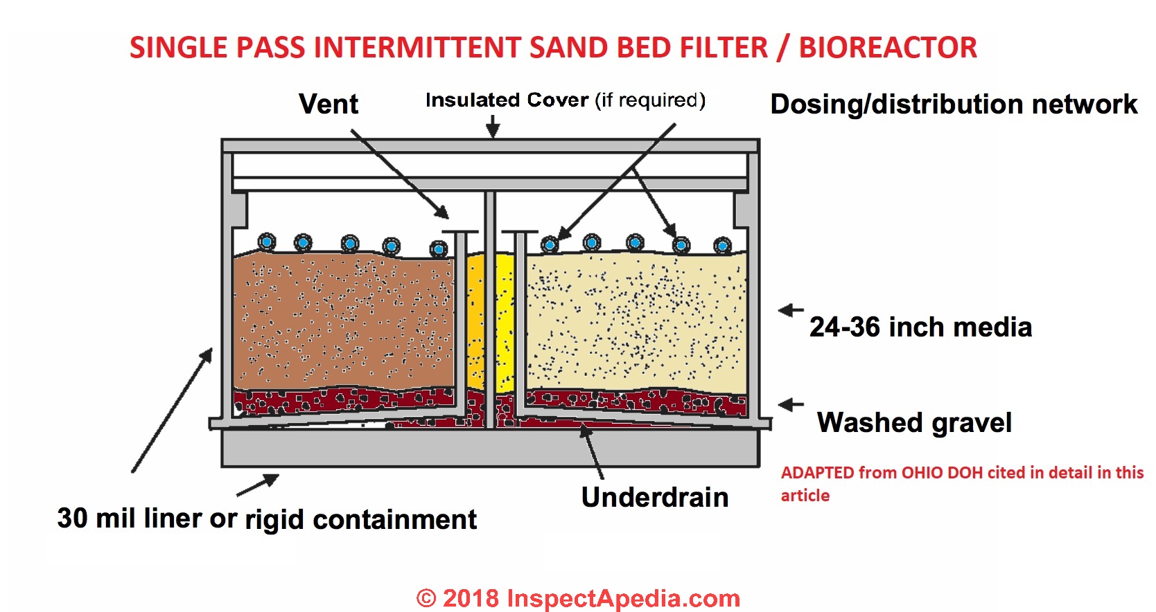
Image of a single pass intermittent sand filter / bioreactor septic, Ohio DOH cited in detail below. [Click to enlarge any image]
- Gustafson, David M., James L. Anderson, Sara F. Heger, and Barbara W. Liukkonen. CHOOSING AN ALTERNATIVE SEPTIC SYSTEM FOR A HOMESITE WITH A HIGH WATER TABLE [PDF] (2000). University of Minnesota Extension, retrieved 2021/03/30 original source: https://conservancy.umn.edu/bitstream/handle/11299/94144/1/7571.pdf
This article discusses the use of a recirculating sand filter septic system. - King County, WA, SAND MOUND SEPTIC SYSTEM HOMEOWNERS MANUAL [PDF] (1999) King County/Seattle Washington, 14350 SE Eastgate Way, Bellevue WA 98007 USA, Tel: 206-477-8050, retrieved 2022/03/07
- King County, WA, SAND FILTER SEPTIC SYSTEM HOMEOWNERS MANUAL [PDF] King County/Seattle Washington, 14350 SE Eastgate Way, Bellevue WA 98007 USA, Tel: 206-477-8050, retrieved 2022/03/07
- Lesikar, Bruce, SAND FILTER SEPTIC SYSTEMS, [PDF] (1999) Texas Agricultural Extension Service, Texas A&M University, retrieved 2018/09/01, original source: https://www.h-gac.com/community/water/ossf/OSSF-Treatment-Systems_Sand-Filter.pdf
- New York - SAND FILTER SEPTIC DESIGN SPECIFICATIONS [Web article providing the specifications] - Appendix 75-A.9 - Alternative Septic Systems [Regulation and System Design Criteria for Raised Septic Systems, Septic Mound Systems, Intermittent Sand Filter Bed Systems, Evaporation-Transpiration Septic Systems, Evaporation-Transpiration Absorption Septic Systems, and Other Alternative Septic Systems] Effective Date: 12/01/1990 - contained in the article above - this page.
- New York Appendix 75-A.9 ALTERNATIVE SEPTIC SYSTEM CODE - INTERMITTENT SAND FILTER BED SEPTIC [web article] section 9.d Intermittent Sand Filter Bed Septic Systems. Section 75-A.9 Alternative Septic Systems - (d)
- New York State Septic Code: Title: Appendix 75-A.9 - Alternative Septic Systems [Regulation and System Design Criteria for Raised Septic Systems, Septic Mound Systems, Intermittent Sand Filter Bed Systems, Evaporation-Transpiration Septic Systems, Evaporation-Transpiration Absorption Septic Systems, and Other Alternative Septic Systems] Effective Date: 12/01/1990
- Ohio, SAND MOUND SEPTIC DESIGN SPECIFICATIONS [PDF] Regulation 3701-29-15-ApdxB retrieved 2017/10/20, original source: http://www.odh.ohio.gov/
- Ohio, SINGLE PASS INTERMITTENT SAND FILTER BIOREACTOR SEPTIC DESIGN [PDF] Ohio Department of HEalth, retrieved 2018/09/01 original source: https://www.odh.ohio.gov/~/media/ODH/ASSETS/Files/eh/STS/ho-FSsandfilter.ashx
Illustrated in sketch above, adapted from the original document cited here.
Description excerpt:
Single Pass Intermittent Sand Filters (ISFs) are fixed-film biological treatment units. In ISFs, wastewater is applied in intermittent doses to a bed of sand or other suitable media.
The wastewater first receives primary treatment in a septic tank or an aerobic treatment unit, and then is pumped from a screened vault in the septic tank or separate dosing tank to the water-tight lined sand bed or module where it is evenly distributed over the top of the sand filter bed. Media alternative to sand has been utilized in some designs.
As the wastewater passes through the sand filter, treatment is accomplished by physical, chemical and biological actions. The main treatment is accomplished by the microorganisms attached to the filter media. The treated wastewater is collected in underdrains at the bottom of the sand filter and is then transported to the soil absorption system.
ISFs are designed such that the pretreated wastewater passes through the sand filter bed once. With proper design and media sizing ISF’s achieve reductions in biochemical oxygen demand (BOD), total suspended solids (TSS), and fecal coliform. However, this pretreatment device has not been approved in Ohio for soil absorption or soil depth credit reductions.
...
Continue reading at SAND FILTER SEPTIC DESIGN SPECIFICATIONS or select a topic from the closely-related articles below, or see the complete ARTICLE INDEX.
Or see these
Sandy Soil Septic System Articles
- AEROBIC SEPTIC SYSTEMS, ATUs - home
- ALTERNATIVE DESIGN SEPTIC SYSTEM SUPPLIERS
- SEPTIC CONSULTANTS, DESIGNERS, ENGINEERS
- BAT MEDIA SEPTIC PLANTS
- BED the SEWER LINE in SAND
- MEDIA FILTER SEPTIC SYSTEMS - home
- SAND BED SEPTIC SYSTEMS
- SAND SEPTIC MEDIA FILTERS
- SAND FILTER SEPTIC DESIGN SPECIFICATIONS
- SANDY SOIL SEPTIC DESIGNS
- SEPTIC MEDIA FILTER CAPACITY & MAINTENANCE
- SEPTIC MEDIA FILTER SOURCE LIST
- SEPTIC MEDIA FILTER SYSTEM OPERATION
- SEPTIC SYSTEM DESIGN ALTERNATIVES - home
- SEPTIC SYSTEM DESIGN BASICS - home
- TYPES OF SEPTIC SYSTEMS - master list
Suggested citation for this web page
SAND BED SEPTIC SYSTEMS at InspectApedia.com - online encyclopedia of building & environmental inspection, testing, diagnosis, repair, & problem prevention advice.
Or see this
INDEX to RELATED ARTICLES: ARTICLE INDEX to SEPTIC SYSTEMS
Or use the SEARCH BOX found below to Ask a Question or Search InspectApedia
Ask a Question or Search InspectApedia
Try the search box just below, or if you prefer, post a question or comment in the Comments box below and we will respond promptly.
Search the InspectApedia website
Note: appearance of your Comment below may be delayed: if your comment contains an image, photograph, web link, or text that looks to the software as if it might be a web link, your posting will appear after it has been approved by a moderator. Apologies for the delay.
Only one image can be added per comment but you can post as many comments, and therefore images, as you like.
You will not receive a notification when a response to your question has been posted.
Please bookmark this page to make it easy for you to check back for our response.
IF above you see "Comment Form is loading comments..." then COMMENT BOX - countable.ca / bawkbox.com IS NOT WORKING.
In any case you are welcome to send an email directly to us at InspectApedia.com at editor@inspectApedia.com
We'll reply to you directly. Please help us help you by noting, in your email, the URL of the InspectApedia page where you wanted to comment.
Citations & References
In addition to any citations in the article above, a full list is available on request.
- New York State Department of Health, APPENDIX 75-A WASTEWATER TREATMENT STANDARDS - INDIVIDUAL HOUSEHOLD SYSTEMS , [PDF] New York State Department of Health, 3 February 2010, retrieved 3/1/2010, original source: https://www.health.ny.gov/regulations/nycrr/title_10/part_75/appendix_75-a.htm
- Heger, S., J. Anderson and B. McCarthy. 2001. Evaluation of recirculating sand filters in a northern climate. 9th
National Symposium on Individual and Small Community Sewage Systems, ASAE, St. Joseph, MI 49085-9659
USA. - Recirculating sand bed filter septic systems - references & product sources:
- Anderson, D.L., R.L. Siegrist, and R.J. Otis. 1985. Technology Assessment of Intermittent Sand Filters. U.S. Environmental Protection Agency, Office of Research and Development, and Office of Water, Publication, Washington, DC.
- Ayres Associates. 1997. Florida Keys Wastewater Nutrient Reduction Systems Demo Project: Second Quarter Report. Florida Department of Health, Tallahassee, FL.
- Ayres Associates. 1998. Unpublished data from Wisconsin.
- Bruen, M.G., and R.J. Piluk. 1994. Performance and Costs of Onsite Recirculating Sand Filters. In Proceedings of the Seventh On-site Wastewater Treatment Symposium. American Society of Agricultural Engineers, St. Joseph, MI.
- Kerri, K.D., and J. Brady. 1997. Small Wastewater System Operation and Maintenance: Vol. 1. California State University, Sacramento, CA.
- Louden, T.L., D.B. Thompson, L. Fay, and L.E. Reese. 1985. Cold-Climate Performance of Recirculating Sand Filters. In Proceedings of the Fourth On-site Wastewater Treatment Symposium. American Society of Agricultural Engineers, St. Joseph, MI.
- National Small Flows Clearinghouse. 1998. Recirculating Sand Filters. U.S. Environmental Protection Agency, Office of Water, Washington, DC.
- Orenco Systems, Inc. 1993. Cost Estimating for STEP Systems and Sand Filters. Orenco Systems, Inc., Roseburg, OR.
- Owen, J.E., and K.L. Bobb. 1994. Winter Operation and Performance of a Recirculating Sand Filter. In Proceedings of the WEFTEC 67th Annual Conference. Water Environment Federation, Alexandria, VA.
- Piluk, R.J., and E.C. Peters. 1994. Small Recirculating Sand Filters for Individuals Homes. In Proceedings of the Seventh On-site Wastewater Treatment Symposium. American Society of Agricultural Engineers, Joseph, MI.
- Rhode Island Department of Environmental Management. 2000. Sand Filter Guidance Document. Rhode Island Department of Environmental Management, Providence, RI.
- Roy, C., and J.P. Dube. 1994. A Recirculating Gravel Filter for Cold Climates. In Proceedings of the Seventh On-site Wastewater Systems Symposium. American Society of Agricultural Engineers, St. Joseph, MI.
- Advanced Onsite Wastewater Systems Technologies, Anish R. Jantrania, Mark A. Gross. Anish Jantrania, Ph.D., P.E., M.B.A., is a Consulting Engineer, in Mechanicsville VA, 804-550-0389 (2006). Outstanding technical reference especially on alternative septic system design alternatives. Written for designers and engineers, this book is not at all easy going for homeowners but is a text I recommend for professionals--DF.
- Onsite Wastewater Disposal, R. J. Perkins; Quoting from Amazon: This practical book, co-published with the National Environmental Health Association,
- Onsite Wastewater Treatment Systems, Bennette D. Burks, Mary Margaret Minnis, Hogarth House 1994 - one of the best septic system books around, suffering a bit from small fonts and a weak index. While it contains some material more technical than needed by homeowners, Burks/Minnis book on onsite wastewater treatment systems a very useful reference for both property owners and septic system designers.
- Septic Tank/Soil-Absorption Systems: How to Operate & Maintain, Equipment Tips, U.S. Department of Agriculture, 8271 1302, 7100 Engineering, 2300 Recreation, September 1982, web search 08/28/2010, original source: http://www.fs.fed.us/t-d/pubs/pdfimage/82711302.pdf
- In addition to citations & references found in this article, see the research citations given at the end of the related articles found at our suggested
CONTINUE READING or RECOMMENDED ARTICLES.
- Carson, Dunlop & Associates Ltd., 120 Carlton Street Suite 407, Toronto ON M5A 4K2. Tel: (416) 964-9415 1-800-268-7070 Email: info@carsondunlop.com. Alan Carson is a past president of ASHI, the American Society of Home Inspectors.
Thanks to Alan Carson and Bob Dunlop, for permission for InspectAPedia to use text excerpts from The HOME REFERENCE BOOK - the Encyclopedia of Homes and to use illustrations from The ILLUSTRATED HOME .
Carson Dunlop Associates provides extensive home inspection education and report writing material. In gratitude we provide links to tsome Carson Dunlop Associates products and services.
 | HOME | ABOUT | ASK a QUESTION | CONTACT | CONTENT USE POLICY | DESCRIPTION | POLICIES | PRIVACY | |
| © 2025 - 1985 Publisher InspectApedia.com - Daniel Friedman | |||||||||