
InspectAPedia® FREE Encyclopedia of Building & Environmental Construction, Diagnosis, Maintenance & Repair |
Question? Just ask us! InspectAPedia
|
 Inspection & Repair Guide for Low Voltage Building Wiring & Lighting Systems
- POST a QUESTION or COMMENT about how to diagnose & repair, replace, or upgrade low-voltage switched 120V lighting or receptacle devices in buildings
Low voltage wiring & control system inspection, troubleshooting, repair, repalcement, upgrades.
Home page for our diagnosis and repair guide for low voltage electrical wiring typically used to control 120V home lighting, electrical receptacles, and other devices.
In this artile series we discuss low voltage electrical wiring inspection, diagnosis, repair, parts replacement, finding low voltage relays, replacing low voltage relays, finding low voltage wiring diagrams, and low voltage electrical wiring parts from GE®, Remcon, Sweepe, Bryant, Sierra, Touch-Plate®, general use low voltage relays, and where to find home electrical system low voltage wiring diagrams helpful for performing low voltage wiring repairs.
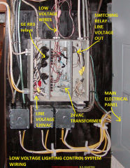
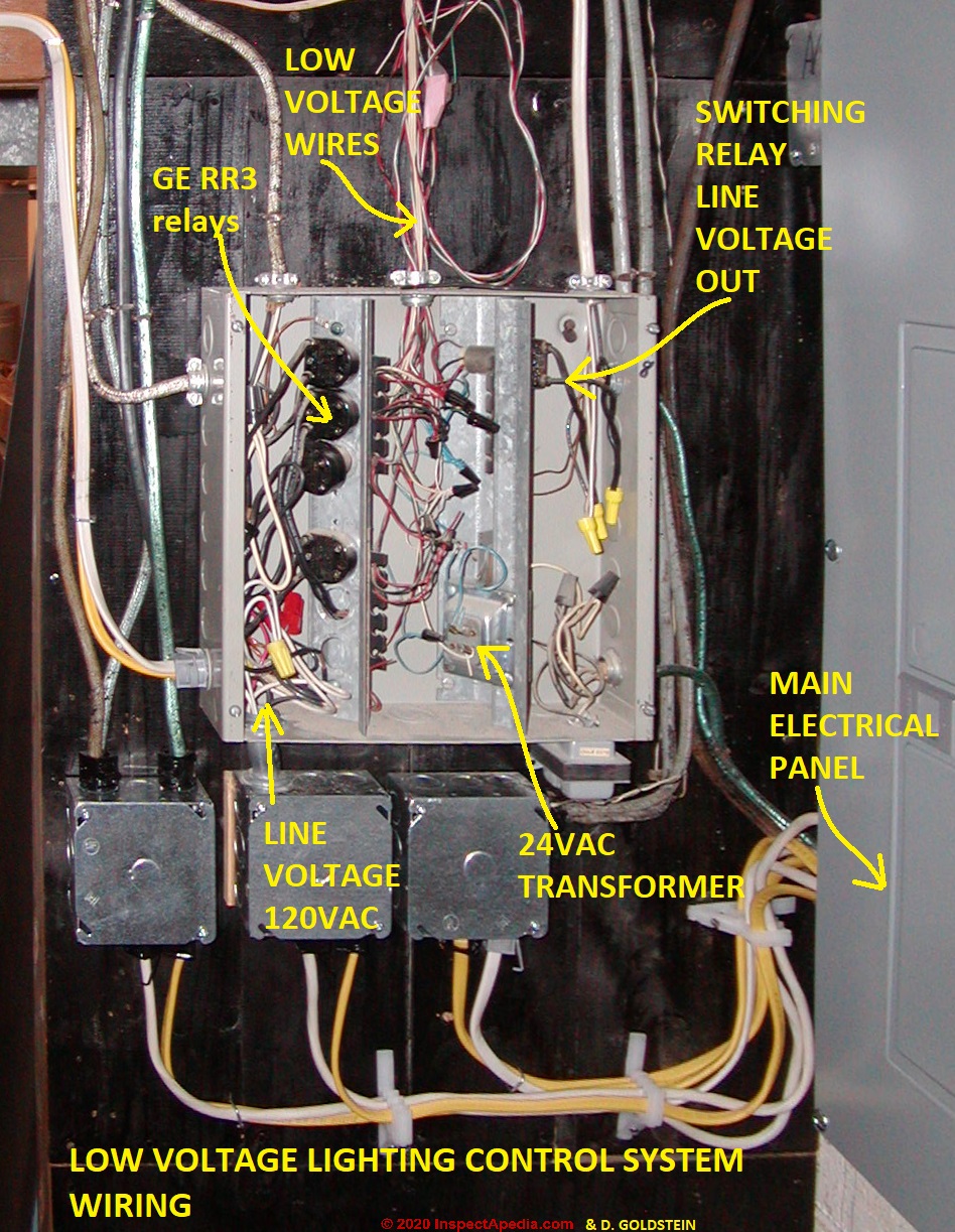
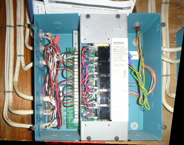
Page top photo: a building low voltage control system switching building 120VAC lighting circuits, illustrating the components of a 24VAC low voltage control system - courtesy of home inspector David Goldstein. [Click to enlarge any image]
InspectAPedia tolerates no conflicts of interest. We have no relationship with advertisers, products, or services discussed at this website.
A Homeowner's Guide to Inspection, Repair, and Replacement of Low-Voltage GE, Remcon, or Other Low-Voltage Building Electrical Wiring & Switches

The photo at left shows a GE low-voltage relay box in a residential attic. Photo courtesy of True Tech Electric.
Low voltage electrical wiring was installed in some homes beginning in about 1946's. This system was popular and was installed in many homes between 1940 a nd 1985, and it continues in use today.
The low-voltage wiring system uses small-gauge copper wires connected to low-voltage switches to switch on and off relays which in turn control the operation of lights and where desired, electrical receptacles, and other 120-Volt equipment in homes.
[Click to enlarge any image]
A power supply or transformer, often called a "transverter" is fed 120V and outputs 28V to the switching system. Pressing the low-voltage switch operates a relay which in turn switches on or off a 120V light or other device in the home.
The low-voltage electrical wiring system popularized in the United States by GE® and Remcon permits the use of less-costly and easier-to-install wiring between the relays and the switches in the home.
The switching relay, or a group of them, is often located in an electrical box in the building's attic, garage, or basement.
At least one supplier continues to design, sell, and service low-voltage home wiring systems: Touch-Plate Lighting Controls, in Fort Wayne IN.
Some of the suggestions and opinions in this article are quoted from or paraphrase advice offered by that company. We provide contact information for Touch-Plate® Lighting Controls below.
Many original GE® or Remcon® low voltage lighting systems are still in use today. But owners of buildings with the original systems installed may find themselves faced with low-voltage switches, relays, or transformers that no longer operate.
Here we describe replacement switches or relays that can be used to repair older low-voltage switching systems in buildings or to install new low-voltage control systems to switch lights, receptacles, motors.
Warning About Repairing Low-Voltage Lighting Systems
Watch out: Owners of such buildings using low-voltage wiring to control lights or other equipment should be careful to perform any repairs or replacements of components in low-voltage electrical systems using only the proper devices.
Installing a conventional 120-V switch or an arbitrary
push switch, or a conventional transformer/voltage converter may not work, and worse, it could be unsafe,
causing a risk of fire or shock.
What are the Components of Low Voltage Lighting Systems?
 A low-voltage wiring system in buildings may be used to operate line-voltage lights, receptacles, motors, or other devices. This system is made up of low-voltage switches that operate relays that actually turn line-voltage on or off to the switched device.
Below we describe each of the key components that make up a low-voltage switching system controlling line-voltage devices.
In this article series we describe low-voltage wiring, controls, and power supplies operating usually at 24VAC and that in turn are used to control line-voltage devices operating usually at 120VAC or 240VAC.
Don't confuse this electrical wiring system with other low-voltage electrical systems in which everything is operating on low voltage (typically 24VAC): the switches, controls, and the electrical devices themselves.
We begin with a list of the key components in any low-voltage wiring & control system used in a building to control lights, receptacles, motors, and equipment. For each of these components we provide links to detailed articles discussing the installation, diagnosis, repair or use of that component.
- LINE VOLTAGE POWER SUPPLY
- LOW VOLTAGE POWER SUPPLY - TRANSFORMER / TRANSVERTER
- LOW VOLTAGE SWITCHES IN BUILDINGS
- LOW VOLTAGE SWITCHING RELAYS USED IN BUILDINGS
- LOW VOLTAGE SWITCHED, 120V ELECTRICAL DEVICES
- LINE VOLTAGE WIRING
- LINE VOLTAGE DEVICES: LIGHTS MOTORS switched by the low voltage system
- LOW VOLTAGE WIRING
- LOW VOLTAGE WIRING OVERCURRENT PROTECTION devices
- LOW VOLTAGE WIRING CONTROL PANEL that may house the tranformer, relays, wiring & other devices
- LOW VOLTAGE WIRING SIZES & OVERCURRENT PROTECTION\
Line-Voltage Power Supply
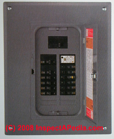
Even when we're talking about low voltage wiring systems, invariably the low voltage electrical power comes first from a line-voltage 120VAC or 220VAC source, then is converted to the necessary lower voltage level. That power source begins at the building's electric meter and main electrical panel.
Photo: a main electrical panel in a building.
In addition, although building lights, receptacles, or other line-voltage devices in the building may be switched on- and off- by low voltage wiring switches and relays, those lights, receptacles, or other devices themselves may require line voltage to operate.
120VAC or in some countries 220VAC "line voltage" electrical power will actually power the switched devices such as interior lighting or electric motors.
Photo: line voltage enters the building through an electric meter and is typically fed to a main electrical panel that in turn provides power to individual 120VAC or 240VAC electrical circuits in the building.
In a building whose lights (or other devices) are controlled by a low-voltage system, one or more of these 120VAC electrical circuits will power one or more low voltage transformers that in turn will provide low voltate (24VAC) to operate switches and relays controllilng the building lighting system.
Low-Voltage Power Supply Transformer / Transverter
 This component feeds electrical power to operate the low voltage switches
and relays in the system.
This component feeds electrical power to operate the low voltage switches
and relays in the system.
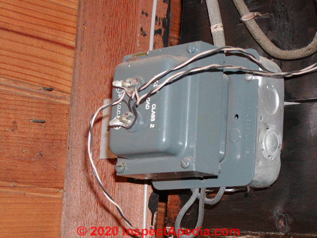
Low Voltage Transformers or Transverters are devices used to provide 24VAC power to the low voltage switches & controls in the building.
Photo:
a low voltage transformer - courtesy of professional home inspector David Goldstein cited at REVIEWERS
This is the operating voltage and current type used to power the switches and the relays that they turn on and off.
Details are
at LOW VOLTAGE TRANSFORMERS, TRANSVERTERS, CONVERTERS
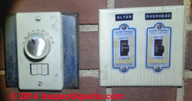
Low Voltage Switches
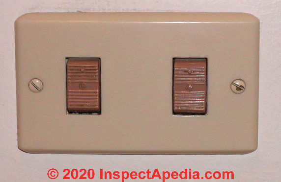
These switches, mounted at the normal height and location in rooms in the building are used
to turn normal 120-Volt building lights, electrical receptacles, or perhaps other 120V devices in the building on and off.
Because installing individual switches and their wiring is lower in cost than installing a 120-volt-rated switch and wire in the same location, a low-voltage-wired home may have multiple switches in multiple locations all controlling the same light or other device.
Details are at LOW VOLTAGE WIRING SWITCHES
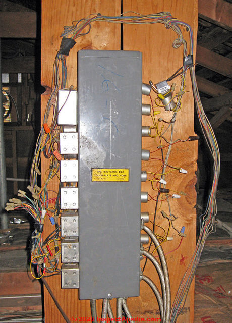
Below: a Touchplate low voltage lighting control panel, photo courtesy of Doug Ford.
Low Voltage Switching Relays
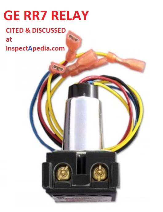 The switching relays (shown below) in a low-voltage electrical system
are turned on or off by low voltage wires coming from the switch.
The switching relays (shown below) in a low-voltage electrical system
are turned on or off by low voltage wires coming from the switch.
Separately, 120V 15-Amp wires bring electrical power into the switch, and similar wires are connected between the switch and the light, electrical outlet, or other 120V device it is intended to control.
When the relay is switched "on" it sends 120V to the device it controls.
When the relay is switched "off" it stops delivering power to the device it controls.
Shown here is a modern GE RR-9 low-voltage switching relay that can be used to replace older GE RR-2, -3, -5 relays.
We discuss the relay wiring connections and types of relays in detail at
LOW VOLTAGE LIGHTING & CONTROL RELAYS
Normal Voltage / Line Voltage (120VAC / 240VAC) Electrical Wiring
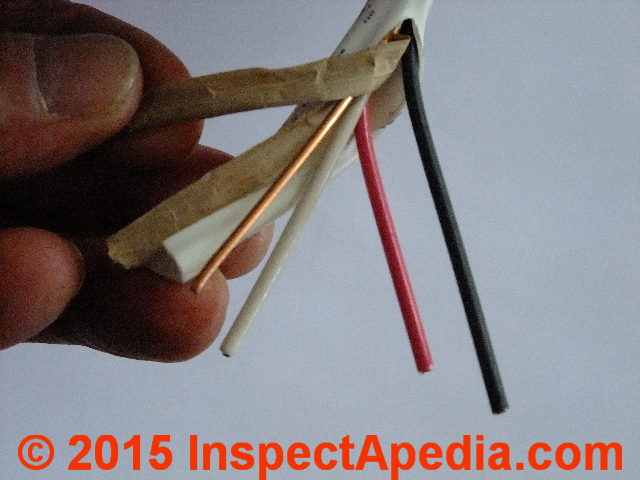
Photo: typical line voltage (120VAC or 240VAC) electrical wiring used in wiring a building 14A or 20A electrical circuit.
The "normal" building electrical wires, typically #14 gauge (for 15-Amp circuits), is used
to carry electrical power into and then out of the low-voltage relay and on to the light, electrical receptacle,
or other device that the switch and relay are intended to control.
Line-Voltage Electrical Devices: Lighting, Motors, Other
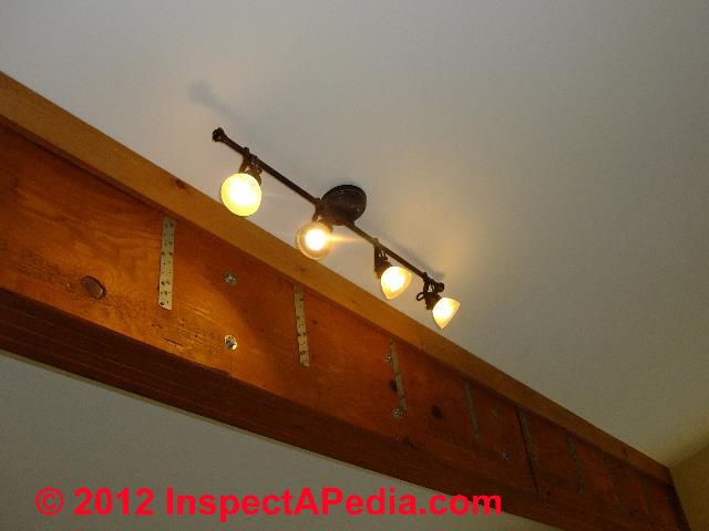
Photo: a conventional line-voltage 120VAC track lighting fixture in a New York home.
Lights, receptacles, other. These are the same 120VAC or 240VAC conventional electrical lights, electrical receptacles, or motors found in buildings.
The device doesn't know that a low-voltage switch is being used to operate a relay that in turn switches its line voltage (120 / 240VAC) on or off.
In the United States most electrical lighting and electrical receptacles are wired to carry 120 Volts A. C. (electric lights and electric receptacles used to power TV's, computers, etc.) or in special cases, 220V A. C. (such as for electric stoves, electric water heaters, and some air conditioning systems.) In the UK and other countries lighting may operate on 220VAC circuits.
Low Voltage Wiring Control Panel
Often the low voltage switching relays, low voltage transformer, and on occasion other low voltage building wiring components are collected in one or more control panels such as this Touchplate Low Voltage Wiring control panel shown below - photo courtesy Doug Ford.
Low Voltage Switches Controlling Lights or Motors
A power supply or transformer, often called a "transverter" is fed 120V and outputs 28V to the switching system. Pressing the low-voltage switch operates a relay which in turn switches on or off a 120V light or other device in the home.
The low-voltage electrical wiring system popularized in the United States by GE® and Remcon permits the use of less-costly and easier-to-install wiring between the relays and the switches in the home. The switching relay, or a group of them, is often located in an electrical box in the building's attic, garage, or basement.
At least one supplier continues to design, sell, and service low-voltage home wiring systems: Touch-Plate Lighting Controls, in Fort Wayne IN. Some of the suggestions and opinions in this article are quoted from or paraphrase advice offered by that company. We provide contact information for Touch-Plate® Lighting Controls below.
Many original GE® or Remcon® low voltage lighting systems are still in use today. But owners of buildings with the original systems installed may find themselves faced with low-voltage switches, relays, or transformers that no longer operate.
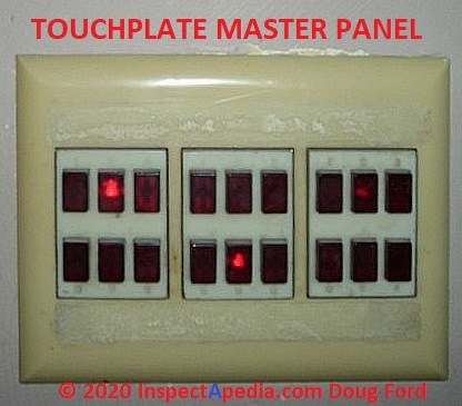
Diagnosing & Repairing Low Voltage Switch Problems
Low-voltage electrical system switches originally made by GE® or Remcon can be replaced with newer ones from Touch Plate but with some provisos which we explain below.
Low-voltage system relays originally made by GE® or Remcon cannot be replaced individually with newer ones from Touch Plate - there are electrical design differences that mean the products are not interchangeable.
Photo: a TouchPlate™ master switching panel, courtesy of Doug Ford.
A home or an entire circuit can, however, be converted over to the new
Touch-Plate® product line. This offers the advantage of permitting the building to continue
to use the existing low-voltage wiring that is already in place between the transformers
and switches.
This approach should be substantially less costly and troublesome than attempting to convert all of the switches in the home to 120V design - that would require re-wiring those areas in the home with new 120V wires.
An old GE® or Remcon® system will work with the Touch-Plate® replacement switches. The GE® and Remcon® systems operate on a three-wire system. One wire is common, one wire is for turning the relay on, and the last wire is for turning the relay off.
Touch-Plate® switches only have two wires. One being the common wire and the other being the switch wire, and because of our single coil relay, the same button is used to turn the relay on and off.
You can use Touch-Plate® switches in place of three-wire switches, but you will need two Touch-Plate® buttons for every one three-wire switch. See Three-wire to Touch-Plate® Wiring Diagram available from Touch-Plate Lighting.
Other Low Voltage Switch Notes
Multi-way switching is supported since multiple switches can all connect to a single relay that controls a single 120V device.
Touch-Plate® says that 3-Way, 4-Way and even 5-Way switching is a standard feature of low voltage control systems and almost all old Touch-Plate® installations have multiple switches that control the same relay.
Do NOT ever attempt to replace a momentary action, low voltage Touch-Plate® switch with an off-the-shelf high voltage toggle switch (maintain / latching style). This will definitely bring in immediate failure of the system.
Painted switch plate covers, cracked covers, and wall-papered covers all are
likely sources of producing a stuck switch.
Low Voltage Wiring
Thin copper wires, typically #22 gauge when used for controlling low-voltage lighting relays or thermostats, is used to connect the low-voltage switches to the relays that each switch controls.
Typically each wire is a single solid conductor.
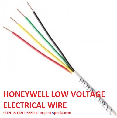
Low voltage copper electrical wire is also sold in multi-strand form for greater flexibility, and in other sizes such as 18-gauge and 16-gauge more-often used for outdoor low-voltage landscape lighting and for automotive uses.
Low voltage wire is also sold in bundled conductors ranging from single wire to (most common in lighting systems) #22/2 two-conductor wires, to color-coded multiple conductor small gauge wires used in alarm systems and in other building device or appliance controllers.
Low Voltage Wiring Sizes & Overcurrent Protection
Normal Voltage (120V) wiring: "normal" building electrical wires, typically #14 gauge (for 15-Amp circuits), is used to carry electrical power into and then out of the low-voltage relay and on to the light, electrical receptacle, or other device that the switch and relay are intended to control.
Don't confuse the wiring requirements for low-voltage-operated switches that operate 120V devices (lights, receptacles etc) with the electrical wiring that powers low-voltage (12-V) devices (such as low-voltage downlights described
For controlling the low-voltage-operated switching relays that in turn operate 120V devices in buildings (lights, receptacles), very thin copper wires, typically #22 gauge, is used to connect the low-voltage switches to the relays that each switch controls.
In contrast, Lucifer Lighting and others point out that when selecting an electrical wire (conductor) size for the low-voltage devices such as downlights used indoors or outside, the wire needs to be chosen based also on the distance between the light fixture and the low voltage transformer.
Lucifer's installation instructions for downlights provides this helpful table of wire lengths and size requirements for low voltage wiring based on distance between the fixture and the transformer:[14]
Maximum Low-Voltage Wire Sizes & Wire Length from Transformer (in feet given secondary wire sizes below) |
|||||||||||||||
| Watts / 12V | 20 | 40 | 60 | 80 | 100 | 120 | 140 | 160 | 180 | 200 | 220 | 240 | 260 | 280 | 300 |
| Amps / 12V | 1.7 | 3.3 | 5.0 | 6.7 | 8.3 | 10.0 | 11.7 | 13.3 | 15.0 | 16.7 | 18.3 | 20.0 | 21.7 | 23.3 | 25.0 |
| Wire Size | Maximum wire length (distance from Transformer in feet) |
||||||||||||||
| 12 AWG | 65 | 33 | 22 | 16 | 13 | 11 | 9 | 8 | 7 | 7 | 6 | 5 | - | - | - |
| 10 AWG | 104 | 52 | 35 | 26 | 21 | 17 | 15 | 13 | 12 | 10 | 9 | 8 | 7 | 7 | 7 |
| 8 AWG | 165 | 83 | 55 | 41 | 33 | 28 | 24 | 21 | 18 | 17 | 15 | 14 | 13 | 12 | 11 |
| 6 AWG | 263 | 132 | 88 | 66 | 53 | 44 | 38 | 33 | 29 | 26 | 24 | 22 | 20 | 19 | 18 |
Comparison of Requirements for 120V Device Wiring Fusing, Low-Voltage Device/Wiring Fusing & Low Voltage Switching-Relay Fusing
Don't confuse these three types of devices, their wiring, and their fusing requirements:
- Fusing on 120V circuits powering lights, electrical receptacles, and other such devices.
120V or 240V devices and the wiring supplying them are normally protected from overcurrent at an electrical panel or sub-panel using 120V or two-pole 240V breakers matched to the circuit wire size, such as 15A for #14 copper wire circuits, 20A for #12 copper wire circuits. - Fusing required on low-voltage switching relay circuits
The (1960's and later) low-voltage operated switching relays draw very low current (amperes) and in older homes may not be fused. The 120V circuit that powers the transverter is of course fused as above. But the low-voltage wiring on the low voltage secondary wiring that is operated by wall switches and used to control 120V devices may itself be un fused.
A similar example from contemporary construction includes low-voltage (14V) circuits that power wall thermostats in HVAC systems. These circuits are not fused separately. - Fusing required on low-voltage circuits that power low-voltage devices drawing higher amperage such as 12-V downlights
Low-voltage-wired and powered devices may also require fusing, such as the low-voltage (12-V) downlights described
at LIGHTING, EXTERIOR GUIDE,
It must be remembered that a lower voltage signifies a higher current in amperes. Therefore secondary fusing based a multiplier of 1.25% (NEC) must be used. The conductor on the secondary side of the [low voltage] transformer at 12-volts must be sized for the full load amperage.
Example: 50 watts / 12 volts = 4.16 amps. 4.16 Amps x 1.25 (125%) = 5.20 AMPS. Use a 5-amp fuse, not a 4-amp fuse. - paraphrased from Lucifer Lighting low voltage lighting installation instructions. [14]
GE Low Voltage Lighting Systems
Question: With GE low voltage switches does is matter which wire you use ?
With GE low voltage switches does is matter which wire you use for on off and common.all wires are white with copper.
- Karl kahlenberg · Feb 27, 2021
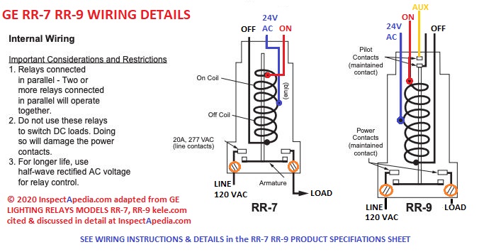
Moderator reply: wiring instructions for GE RR-7 & GE RR-9 Relays
[Click to enlarge any image]
@Karl kahlenberg, Take a look at the GE low voltage relay switch wiring diagram found at
LOW VOLTAGE LIGHTING & CONTROL RELAYS
where you'll also see a PDF download on specs and wiring
with more wiring diagrams
You'll see that on the relay, on the high-voltage (120V) side, there is definitely a LINE and LOAD terminal ID, while at the low-voltage relay side they show a Black = OFF and Red = ON.
When all your wires are the same color (white) I don't think you'll damge the relay by inverted wiring, but if the switch has an "off" direction and an "on" direction you may find on testing that you want to swap your original low voltage connections.
On 2021-04-30 by (mod) - rat's nest of messy wiring at a GE Low-Voltage Lighting Sysetm
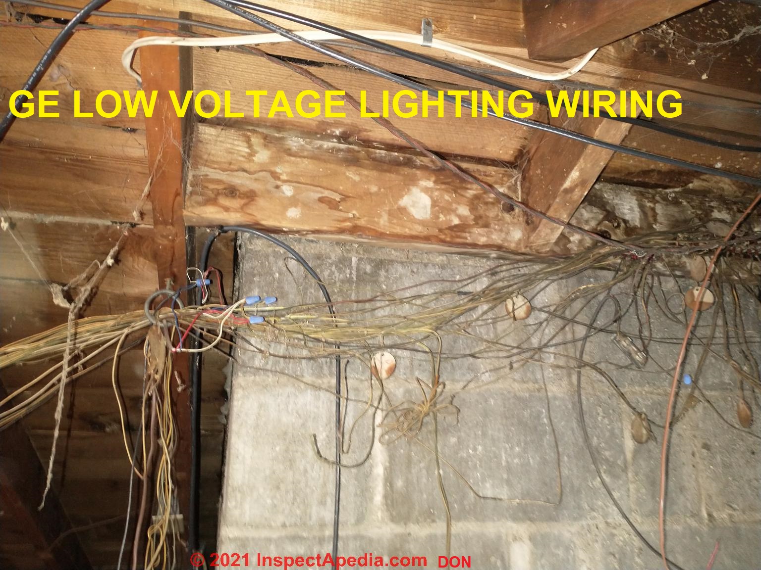 @Don, here's the image, right-way up.
I must say that it's very common to see this in older homes: a veritable rat's nest of wiring that is a bear to sort through.
With so many wires running amok it's pretty easy to develop a short circuit or loose connection that then gives trouble on the low voltage system or even on the 120V side in (or I'm afraid) outside-of wiring junction boxes.
Your electrical resistance tests suggest
- loose wires making an intermittent connection - you need to find that short; check also at each of the relays but especially check near the 120V connections in the lights or other switched devices themselves.
- a shorting or failing LV relay that's switching a particular light on and off
I would make a quick visual inspection of all of the accessible wires, then I'd start disconnecting individual relays and light fixtures to narrow down the area where the problem probably resides.
On 2021-04-29 by Don
I am reposting this without the image so it shows up immediately. When the image is approved it may be upside down.
My house has a GE low voltage lighting system that has worked for 40 years. All of a sudden it started blowing out the primary circuit of the Class II transformer because of a short in the in wiring connected to the Secondary circuit.
When I disconnect the wiring from the transformer and measure the resistance, it will change from 60 ohms to 2 ohms to an open loop throughout the day. There should be no active components in the system. Any ideas on what might cause this to happen?
To the editor. On my preview the image I attached is up side down
On 2021-04-29 by Don
My house has a GE low voltage lighting system that has worked for 40 years. All of a sudden it started blowing out the primary circuit of the Class II transformer because of a short in the in wiring connected to the Secondary circuit. When I disconnect the wiring from the transformer and measure the resistance, it will change from 60 ohms to 2 ohms to an open loop throughout the day. There should be no active components in the system. Any ideas on what might cause this to happen?
Lutron Low Voltage Lighting Systems
Reader comment: Lutron Lumi5 Low-Voltage lighting in a 1988 Pennsylvania Home
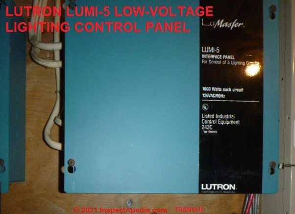 Lutron is manufactured near me [in Pennsylvania]. Several homes have Lutron Low voltage lighting systems. (Relays)
This house was built in 1988.
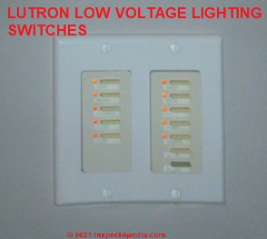
It has master switches in the hallway, and master bedroom.
Pretty cool. however it did not function properly. Considering only 22-gauge wire is run to the switches, changing or repairing this system may be costly.
- Larry Transue [by private email to Editor, 2021/10/24]
- Lawrence Transue is a Pennsylvania building scientist and consultant, a certified ASHI home inspector, a Licensed Pesticide Applicator, a
BPI Building Analyst & Envelope Professional, with
18 Years of Home Inspection Experience. He can be reached by Telephone: 610.417.0763, by Email: lawrence@lawrencetransue.com as well as at his WEBSITE and at FACEBOOK.
Mr. Transue is a frequent contributor to InspectAPedia.com.
Moderator reply:
 I don't think the wire gauge is an issue for low voltage wiring sysetm as long as the homeowner stays with low voltage for lighting controls (We should review what Lutron says about wire gauge requirements for their systems and controls.)
22-gauge coopper wire is common in low voltage control systems for lighting.
One wouldn't pan LV wiring per-se, as in our OPINON not only is the control wiring less expensive and easier to run in a new-construction job but in some respects its safer (fire and shock risks) as we've got only low voltage at controls and through parts of the building.
I agree, however, that changing ANY such LV system to more-conventional 120V wiring for lighting controls is indeed a costly deal.
People are tempted to do so when they can't find repair parts - principally relays and switches that for Lutron ought to be available.
Did you find functional issues?
Was your client worried about the system?
These documents from Lutron may be of assistance.
Incidentally, these controls can operate LEDs, CFLs, as well as incandescent bulbs and halogen buls up to 600W.
Lutron also provides LED lighting and dimmer controls that can work with these systems.
- Contact: Lutron Electroncis Col, Inc., 7600 Suter Road, Coopersburg, PA 18036-1299, USA
- Lutron DIMMERS, SWITCHES, REMOTES INSTALLATION MANUAL [PDF] (2008) Architectural-Style Wired Maestro® Dimmers, Switches, and Remotes HWA-5E-CE, HNA-5E-CE, HWA-2ANS-CE, HNA-2ANS-CE HA-RD-CE, HA-RS-CE 220–240 V 50 Hz
- Lutron LTMI-5 INTERFACE PANEL INSTALLATION INSTRUCTIONS [PDF] (1996) Lutron, Inc., retrieved 2021/10/25 original source: https://www.lutron.com/TechnicalDocumentLibrary/030466a.pdf
- Lutron LED System IO Manual [PDF] Op. CIt.
- Lutron LOW VOLTAGE LIGHTING CONTROL PANEL WIRING DIAGRAMS [PDF] (1992), Lutron, Inc., retrieved 2021/10/25 original source: https://www.lutron.com/TechnicalDocumentLibrary/030295%20b.pdf
Reader Comments, Questions & Answers About The Article Above
Below you will find questions and answers previously posted on this page at its page bottom reader comment box.
Reader Q&A - also see RECOMMENDED ARTICLES & FAQs
On 2021-03-16 by (mod) - Lightough Low Voltage Wiring Lighting System - out of business
@Emmett,
Sure
Take a look at https://inspectapedia.com/electric/Low_Voltage_Home_Wiring_Repair.php LOW VOLTAGE WIRING REPAIR or UPGRADE
On 2021-03-16 by Emmett
My home has a low voltage system mfgs. by Lightough, who is now out of business. I am having various problems with the system and the electrical contractor that installed the system is reluctant to help. Do you know of any mfgs. that I might consider using or other suggestions. We are in Clearwater, Florida. Thanks much
Question: is it OK to use #14 wire in a low voltage wiring system?
I am looking at buying a small cabin with 14 gauge 110v wire already run. If I wanted a low voltage system, can I use the existing wire or is it too big? - Anonymous by private email 2020/12/17
Moderator reply:
It's always perfectly safe to use a larger wire then the current or amperage would require as long as you can make mechanically sound electrical connections. It has lower resistance than a smaller diameter wire.
The only problem you may encounter is in making connections to some low voltage equipment - the connectors may only accept a smaller gauge wire. In that case what you do is use a twist-on connector to connect a short pigtail of small diameter wire to make the final connection. Only if necessary.
Watch out: Take great care however that there's no mixing between 110 or 120 volt and low voltage wiring connections. If there is higher voltage wiring anywhere in the building, you need to be sure that there's no way it can accidentally be connected to the network of wires that are in your low voltage system. I mention it because people may be confused in the future when they see the larger gauge wire used in a low voltage systems
On 2020-11-24 - by (mod) -
If the camera works at all during the installation procedure I doubt there's a voltage problem;
More likley we've tripped over one of the installation steps. For some cams we needed to first set it up by direct connection to a laptop USB port;
Newer cams, I've found, can be darn hard to set up with a computer but are a piece of cake (easy to set up) using the smartphone app for the camera.
Try that
On 2020-11-23 by Christine
Sorry that sent before I was done. Could the low-voltage be the reason,my security camera won't connect to the net?
Hi, I have a new security camera, wired to an old light fixture. My house was built in 1947. I understand that the voltage going to light switches then, was of a lower voltage could that be the reason my security cameracannot
On 2020-08-14 by Lois
Why did my part of my low voltage lights and outlets quit working while others srill work?
On 2020-02-01 - by (mod) -
 Michael
Thanks for a helpful question.
Short answer: either relay will work if the relay itself is good.
Please find your question repeated along with my very detailed reply now at
LOW VOLTAGE LIGHTING & CONTROL RELAYS
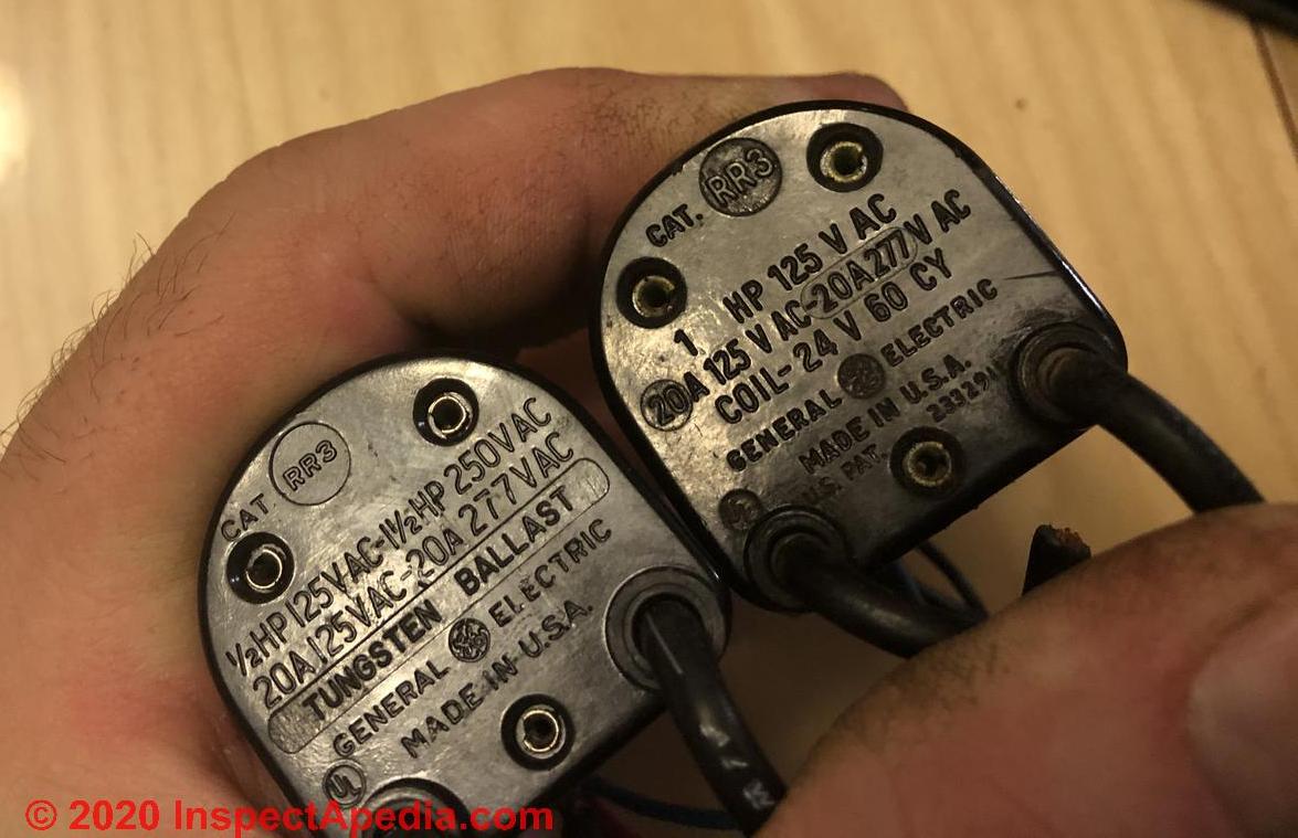
On 2020-01-31 by Michael Melcher
What’s the difference from 1HP to a 1/2HP realay.? I have no more 1HP and a bunch of 1/2 HP that came with the house. Can I put the 1/2 HP for the light switch? When the original is a 1HP?
On 2019-09-23 - by (mod) -
An easy low Tech pair of test steps would be to First swap the switch for a known good one and if that makes no change swap the relay for one from a circuit that's working. That's a pair of test you can do with no test equipment at all.
On 2019-09-22 by Bill
I have an older low voltage system in my home built in 1953. One of the switches will turn turn outside flood lights on but not off. All other switches operate properly in the house. Bad switch or relay? How do I test?
On 2019-05-28 - by (mod) -
You want to find the first electrical receptacle ins-dream of ones that are dead because that's likely to be where you have a broken connector
On 2019-05-27 by Rob
I have the old low voltage system. I think it is GE but not 100% sure. Problem is I have 6 120v outlets not working. Lights and light switches do work.
I checked each outlet and all the circuit breakers. Found nothing wrong. Not sure what to check or do next. If light works but outlet doesnt where do I go or check next? If relay is bad could the light switch still work but not the outlet?
On 2018-08-20 by (mod) - How do I trouble shoot low voltage to the lights i
Coy
In essence, follow the wires.
If the problem is a switch then jumping the switch wires will turn the lights on.
If the problem is a relay, swapping one from lights that work can confirm that was the issue.
Watch out: if you're not familiar and trained in electrical work you could be shocked or killed, especially at the line voltage connections and wires.
On 2018-08-20 by Anonymous
@Coy R Nichols,
How do I trouble shoot low voltage to the lights in bathroom , bed room and bathroom. They don’t work
Diagnosing & Repairing or Replacing Low Voltage Wiring Transformers or Transverters
This has moved to DIAGNOSE & REPAIR OR REPLACE LOW VOLTAGE TRANSFORMERS OR TRANSVERTERS
Basics of Wiring Low Voltage Transformers
This discussion is now at BASICS OF WIRING LOW VOLTAGE TRANSFORMERS
How to Choose the Right Transformer for Home Low Voltage Wiring Systems
This discussion is now at BASICS OF WIRING LOW VOLTAGE TRANSFORMERS
Suggestions for Upgrading Low Voltage Building Electrical Wiring Switches, Relays, and Transformers
This discussion is now found at UPGRADE LOW VOLTAGE ELECTRICAL WIRING SWITCHES, RELAYS, TRANSFORMERS
Repair Parts Sources for Low Voltage Home Wiring Systems
This list moved to WHERE TO BUY REPAIR PARTS FOR LOW VOLTAGE HOME WIRING SYSTEMS
Low Voltage Relays Controlling Lighting or Motors
Moved to LOW VOLTAGE LIGHTING & CONTROL RELAYS
...
Continue reading at LOW VOLTAGE WIRING REPAIR or UPGRADE or select a topic from the closely-related articles below, or see the complete ARTICLE INDEX.
Or see LOW VOLTAGE BUILDING WIRING FAQs - questions and answers posted originally on this page.
Or see these
Recommended Articles
- BOILER CONTROLS & SWITCHES
- FURNACE CONTROLS & SWITCHES
- HEAT WON'T TURN OFF
- HEAT WON'T TURN ON
- LOW VOLTAGE BUILDING WIRING - home
- COMMON WIRE at THERMOSTATS
- LOW VOLTAGE WIRING SYSTEM COMPONENTS
- LOW VOLTAGE LIGHTING & CONTROL RELAYS
- LOW VOLTAGE TRANSFORMERS, TRANSVERTERS, CONVERTERS
- LOW VOLTAGE TRANSFORMER, TRANSVERTER DIAGNOSIS
- LOW VOLTAGE TRANSFORMER TEST
- LOW VOLTAGE TRANSFORMER WIRING GUIDE
- LOW VOLTAGE WIRING REPAIR or UPGRADE
- LOW VOLTAGE WIRING REPAIR PARTS SOURCES
- THERMOSTAT WIRE CONNECTIONS
- THERMOSTAT WON'T TURN OFF
- THERMOSTAT WON'T TURN ON
- VOLTS MEASUREMENT METHODS
- ZONE DAMPERS
- ZONE VALVES, HEATING
Suggested citation for this web page
LOW VOLTAGE BUILDING WIRING at InspectApedia.com - online encyclopedia of building & environmental inspection, testing, diagnosis, repair, & problem prevention advice.
Or see this
INDEX to RELATED ARTICLES: ARTICLE INDEX to ELECTRICAL INSPECTION & TESTING
Or use the SEARCH BOX found below to Ask a Question or Search InspectApedia
Ask a Question or Search InspectApedia
Try the search box just below, or if you prefer, post a question or comment in the Comments box below and we will respond promptly.
Search the InspectApedia website
Note: appearance of your Comment below may be delayed: if your comment contains an image, photograph, web link, or text that looks to the software as if it might be a web link, your posting will appear after it has been approved by a moderator. Apologies for the delay.
Only one image can be added per comment but you can post as many comments, and therefore images, as you like.
You will not receive a notification when a response to your question has been posted.
Please bookmark this page to make it easy for you to check back for our response.
Our Comment Box is provided by Countable Web Productions countable.ca
Citations & References
In addition to any citations in the article above, a full list is available on request.
- www.touchplate.com 800-227-5154 provided basic data for much of the content paraphrased or quoted in this article.
- David Goldstein - contributor and technical review. Mr. Goldstein is a NJ and NY licensed home inspector and Director of Training for Building Inspector's Career Institute, in Robbinsville, NJ, www.InspectoReduction .com
- Some of the GE relay box photos on this page are courtesy of True Tech Electric.
- "Electrical System Inspection Basics," Richard C. Wolcott, ASHI 8th Annual Education Conference, Boston 1985.
- "Simplified Electrical Wiring," Sears, Roebuck and Co., 15705 (F5428) Rev. 4-77 1977 [Lots of sketches of older-type service panels.]
- "How to plan and install electric wiring for homes, farms, garages, shops," Montgomery Ward Co., 83-850.
- "Simplified Electrical Wiring," Sears, Roebuck and Co., 15705 (F5428) Rev. 4-77 1977 [Lots of sketches of older-type service panels.]
- "Home Wiring Inspection," Roswell W. Ard, Rodale's New Shelter, July/August, 1985 p. 35-40.
- "Evaluating Wiring in Older Minnesota Homes," Agricultural Extension Service, University of Minnesota, St. Paul, Minnesota 55108.
- "Electrical Systems," A Training Manual for Home Inspectors, Alfred L. Alk, American Society of Home Inspectors (ASHI), 1987, available from ASHI. [DF NOTE: I do NOT recommend this obsolete publication, though it was cited in the original Journal article as it contains unsafe inaccuracies]
- "Basic Housing Inspection," US DHEW, S352.75 U48, p.144, out of print, but is available in most state libraries.
- In addition to citations & references found in this article, see the research citations given at the end of the related articles found at our suggested
CONTINUE READING or RECOMMENDED ARTICLES.
- Carson, Dunlop & Associates Ltd., 120 Carlton Street Suite 407, Toronto ON M5A 4K2. Tel: (416) 964-9415 1-800-268-7070 Email: info@carsondunlop.com. Alan Carson is a past president of ASHI, the American Society of Home Inspectors.
Thanks to Alan Carson and Bob Dunlop, for permission for InspectAPedia to use text excerpts from The HOME REFERENCE BOOK - the Encyclopedia of Homes and to use illustrations from The ILLUSTRATED HOME .
Carson Dunlop Associates provides extensive home inspection education and report writing material. In gratitude we provide links to tsome Carson Dunlop Associates products and services.
 | HOME | ABOUT | ASK a QUESTION | CONTACT | CONTENT USE POLICY | DESCRIPTION | POLICIES | PRIVACY | |
| © 2024 - 1985 Publisher InspectApedia.com - Daniel Friedman | |||||||||