
 Low Voltage Relays in Lighting Systems
Low Voltage relays to control lights or motors
- POST a QUESTION or COMMENT about how to diagnose & repair, replace, or upgrade low-voltage switched 120V lighting or receptacle devices in buildings
Low voltage relays used to control lighting systems, motors or other devices are discussed here.
This article series provides a diagnosis and repair guide for low voltage electrical wiring typically used to control 120V home lighting, electrical receptacles, and other devices as well as in HVAC system controls.
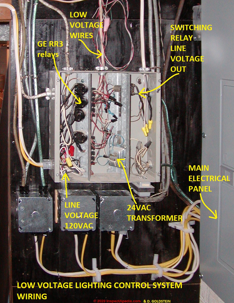
Page top photo: a building low voltage control system switching building 120VAC lighting circuits, illustrating the components of a 24VAC low voltage control system - courtesy of home inspector David Goldstein. [Click to enlarge any image]
InspectAPedia tolerates no conflicts of interest. We have no relationship with advertisers, products, or services discussed at this website.
- Daniel Friedman, Publisher/Editor/Author - See WHO ARE WE?
Low Voltage Relays Controlling Lighting or Motors
 Guide to Diagnosing, Repairing & Wiring Low Voltage Wiring Relays

Switching Relays that work intermittently?
If sometimes when you operate the switch to control a light or receptacle or other device it works just fine, but at other times it fails to operate, giving difficulty in turning the light or receptacle "on" or "off" we could have a problem with the switch itself, or the problem may be with the relay that the switch controls.
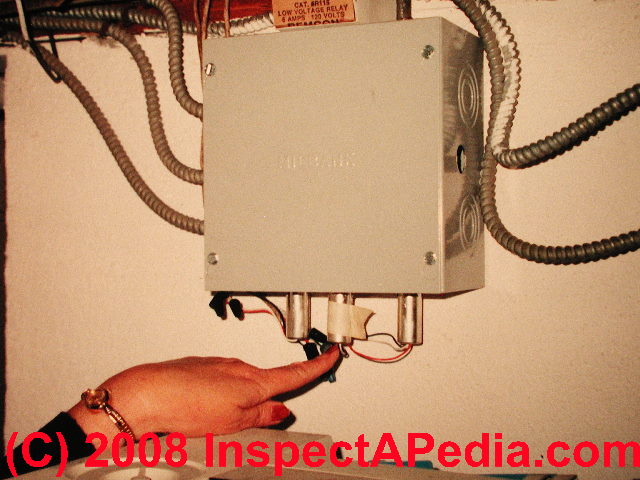
Photo above: a GE Low voltage switching relay control box used for low voltage lighting control.
Check the building first for for sticking low-voltage switches.
If all of the switches appear to be working normally, then find the switching relays that are misbehaving, and check for temperature exposure problems. Switching relays that are too hot or too cold may not work properly.
Low voltage relays may not operate reliably if exposed to below freezing temperatures, or to temperatures above 120 degrees. Depending on where the building is located, these conditions can certainly be encountered in an attic, and cold conditions may be encountered in a garage or crawl space.
Touch-Plate offers a trivial fix for the cold temperature problem: place a light bulb close to the relay panel. Turning the light bulb on during the cold period will usually produce sufficient warmth to keep the switching relays working.
Touch-Plate® also advises "The best solution is to contact the factory for assistance in upgrading the whole system to current technology and relocating the panels to a garage, a basement, a mechanical room, or closet that will avoid this altogether."
Switching Relay Burn-up?
 This can happen with age and use. But if the relays are burning up
after replacement or other repairs to the system, check the low voltage
transformer.
This can happen with age and use. But if the relays are burning up
after replacement or other repairs to the system, check the low voltage
transformer.
The voltage transformer must be one designed for this application. Some generic voltage transformers do not sense that a switch is stuck (or being held depressed for some reason) and lack a limiting function to protect the relay from burn-up.
Replacement relays for existing Touch-Plate® installations can be installed without this worry.
But this is not the case if your relays are the older GE® or Remcon® brand. First, for Touch-Plate® installations, If the relay you are replacing has two wires coming out of the cylinder the relay is a 1550 series and it can be replaced by the Touch-Plate® 2500-B.
If the old relay has four wires coming out of the cylinder of the relay it can be replaced by a Touch-Plate® 2500-BPL.
But what about homes using older GE® or Remcon® relays? Touch-Plate® relays cannot be used to replace individual GE® or Remcon® relays.
The switching relays made by these manufacturers work differently from those designed and sold today by Touch-Plate lighting. For example, Touch-Plate informs us that the Touch-Plate® relay (2500-B) is a single coil, 28VDC latching relay, whereas the the GE® relay (RR-7) is a dual coil, 24VAC latching relay, and the Remcon® relays (depending on the style) are a single or dual coil relay with an internal power supply for each relay.
Also, two switching relays will not operate from a single button press in older systems prior to 1986, they were designed to operate one at a time.
But you can forget the details of just how your relays work if you just remember that you cannot substitute a Touch-Plate® relay for either GE® or Remcon® relays.
So what to do with a GE® or Remcon® relays that no longer work? You can either re-wire that entire individual circuit to use Touch-Plate® components, or, as Touch-Plate Lighting recommends, replace all of the older GE® or Remcon® relays in the home with Touch-Plate® relays. This may not be as horrible as it sounds: you're not replacing wiring, just devices. themselves.
Question: Can I swap in a lower HP-rated relay switch? Replacements for the GE RR3 relay.
 What’s the difference from 1HP to a 1/2HP relay? I have no more 1HP and a bunch of 1/2 HP that came with the house.
Can I put the 1/2 HP for the light switch? When the original is a 1HP?
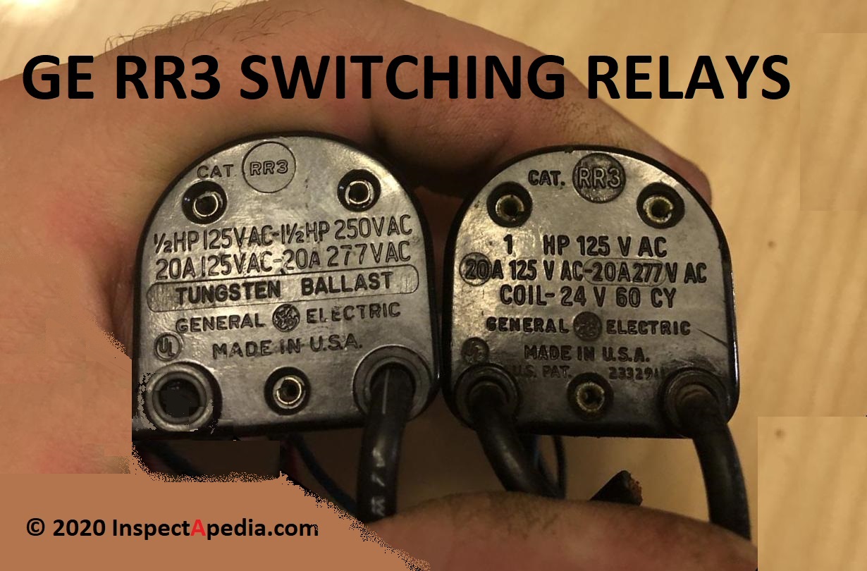
Photo courtesy of InspectApedia reader Michael Melcher 2020/01/31
Reply: Yes in most cases on a low-voltage lighting circuit you can use any GE RR3 relay or you can replace older RR2, RR3 or RR7 relays with a GE RR-7 / RR-9 relay.
Michael:
Thanks for asking a great question: what's the reason that a relay like the GE RR3 in your photo might be rated 1 hp versus 1/2hp?
To answer your question directly, higher horsepower numbers mean that the relay is subjected to greater current
. On a low-voltage lighting circuit (or any other use for that matter) you're fine using the 1/2HP version of the switch as I will explain below. My opinion is based on the observation that in building lighting you're not exceeding the amps or current rating of the switch.
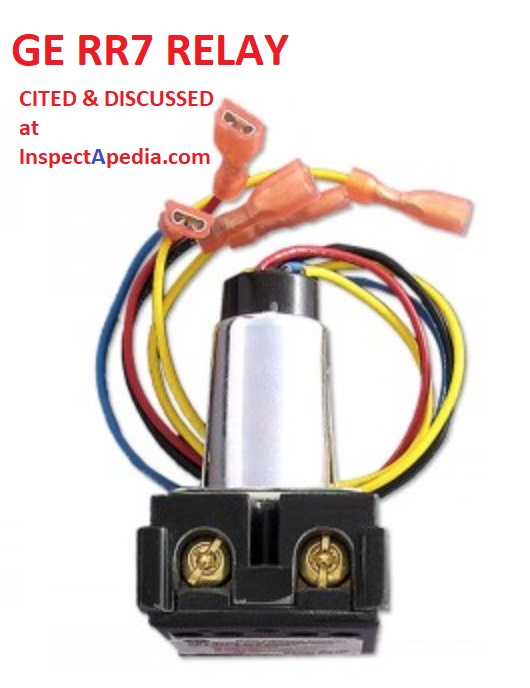
However you can also replace old RR3s with the GE RR7 illustrated here and explained below.
While they had a range of applications, GE RR3 relays were widely used in lighting circuits in homes, particularly low-voltage lighting, and it was used also (I think) in motor start-stop circuits.
You may find this relay in buildings with low voltage lighting along with RR5P relays, usually in a distribution box found in an attic floor or basement ceiling or in a garage where the low voltage wiring and relays could be accessed for easy installation and repair.
If you need to replace your GE RR3s you will want to look at the current GE RR7 relay that can replace the RR2, RR3, and RR5 low voltage “remote control” switching relays. (Available from GE or Bryant, at your local electrical supplier and from numerous online vendors such as Gescan (Sonepar).
It’s a mechanical relay sporting
- 1 common wire lead
- 1 lead to cause the relay to open and stay open (“off”) until a pulse is sent on the close lead
- 1 lead to cause the relay to close
The common wire runs to the center of the relay coil. The other two leads run to the other opposing ends of the coil and thus can cause the relay to open or closed depending on which of the other leads is pulsed.
First let's write down all of the specifications for your two relays:
Leftmost relay in your photo:
GE Catalog No. RR3
1/2HP, 125VAC - 1 1/2HP 250VAC
20A / 25VAC - 20A - 277VAC
Tungsten Ballast produced by GE
Rightmost relay:
GE Cat RR3
1 HP 125VAC
20A 125VAC - 20A 277VAC
Coil-24V 60 CY
Produced by General Electric
Details of Operation & Use & Ratings of the GE RR3 Switching Relay

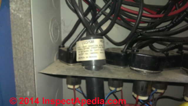
Photo: a GE Low-Voltage lighting control panel showing relays and wiring, courtesy of Doug Ford.
1. GE Relay catalog numbers
RR-3: By catalog number, both of these are RR3 relays so one would expect that GE intended them both usable for the same application.
The current replacement are GE Lighting Relays Models RR-7 or RR-9 for which we include a specifications sheet below.
2. Equivalent GE RR-3's:
While the two relay cite different horsepower numbers, they both cite identical amperage or current rating: this is the significant feature since if you require a relay to carry more current than that for which it was designed it is likely to overheat and fail or perhaps be unsafe.
Both relays cite rating for 20A 125VAC or 20A 277VAC
- A 1/2 HP electric motor draws about 373 watts or at 125VAC single phase current, about 3 amps of current and at 277V about 1.3 amps
- A 1HP electric motor draws about 746 watts or at 125VAC single phase current, about 6 Amps and at 277V about 2.7 Amps
- A 1 1/2 HP electric motor draws about 1119 watts or at 125VAC single phase current, about 9 Amps and at 277V about 4 Amps
So you can see that at these horsepower ratings the actual current passing through the relays is well below their 20A rating - on the safe side.
(I’m not an EE so I may have missed something).
3. RR-3 relay details
The left relay in the Melcher GE relay photo on this page includes the words TUNGSTEN BALLAST missing from its sister and lacks a patent number.
 However this feature pertained to both relays. From GE's current lighting relay specifications we have
All GE low voltage relays may be used to full-rated capacity for tungsten filament, ballast, or resistive loads.
4. There is no important difference between the two GE RR-3 relays in your photo
These relays are identical in intended use but were produced at different times and were labeled differently as GE's labeling rules changed.
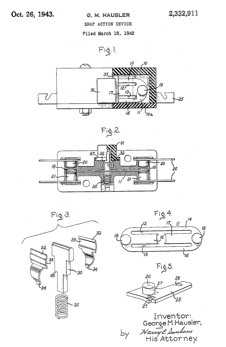
It's possible that the right hand relay, bearing US Patent No. 2332911 is the older.
This patent, by G.M. Hausler was filed in 1942 and granted 1943-10-26
- Hausler, G.M., General Electric Co, 1943. SNAP ACTION DEVICE. U.S. Patent 2,332,911 [PDF] (1943) .
It’s described as a “snap action” switch classified as “Snap-action arrangements depending upon deformation of elastic members using flexing of blade springs having a symmetrical configuration”
The patent illustration we include here illustrates how the switch works. I like this excerpt from Hausler:
Such a device may be built in very small sizes and, when used to actuate the contacts of an electric switch, the switch possesses remarkable interrupting capacity for both alternating and direct current in comparison to its physical dimensions.
The switch is suitable for precision work, since movement of the actuating member required to effect circuit-making or circuit breaking movement of the contacts is quite small and remains substantially constant.
For example, in a typical switching device in which the switch member of spring material was approximately one inch in length, the actuating movement was approximately one thirty-second of an inch and was found to be substantially invariable after many thousands of operations.
In the device the contact movement was of the order of only one hundredth of an inch, yet this switch successfully interrupted the current of a one half horsepower stalled rotor capacitor motor thousands of times. - (Hausler 1943)
GE RR- series Lighting Relay Wiring Details
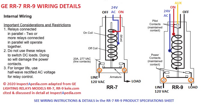
Illustrated here, RR-7 / RR-9 wiring details adapted from the product specifications cited below. Be sure to see additional wiring instructions and details in that document.
The GE RR-9 relay is essentially the same control as the GE RR-7 with the addition of an auxiliary contact on the low voltage side of the relay used to power an indicator light that will show if the device has been switched ON.
[Click to enlarge any image]
Excerpted / adapted from the product specifications cited and given in PDF form below.
Watch out: the current product specifications, cited above, warn that in the GE Model RR-7 and RR-9 the coil is designed to resist burnout if continuous voltage is applied, but coil life may be shortened with prolonged, continuous voltage.
Each relay provides two terminals, two back wiring holes per terminal for use with #14-10 AWG solid or stranded wire (copper wire only).
- GE LIGHTING RELAYS MODELS RR-7 & RR-9 SPECIFICATIONS [PDF] at GESCAN, a Sonepar company and a supplier of the GE-RR7 20A 120-277VAC SPST low voltage general electric remote control relay switch described here.
Retrieved 2020/01/31 original source: https://www.gescan.com/products/lighting/ge-rr7-30166 original publisher: 2004 KELE CATALOG, www.kele.com, Tel: USA 888-397-5353 Tel International 901-382-6084
Website excerpt from the product description:
Product Description New GE RR7 maintained relay switch comes equipped with 3 low voltage leads and is the best replacement option for discontinued GE relays for standard unlighted switches.
These relays are also a compatible replacement for standard Sierra Electric and Bryant brand solenoid relays and have a split low voltage (24V) coil to move the line voltage contact between latched ON and OFF positions.
Features -rated 20 amp, 277 volt -SPST (single pole single throw) mechanical relay -1.5" W x 1.75" D x 2.5" H; 7/8" diameter cylinder -3 low voltage leads - one red, one black, one blue -special coil design to resist burnout -can operate in any position - replaces discontinued GE RR2, RR3 and RR5 and standard Bryant low volt solenoid relays.
(Use a GE RR9 relay if replacing a GE RR4, RR6 or RR8.) -UL Listed, CSA certified -made in India for GE Lighting Solutions -can be used to replace a Sierra relay or a Bryant relay of a similar type
Excerpts from the product specification document:
GE Model RR-7 and RR-9 Lighting Relays are mechanical latching-type units requiring only momentary 24 VAC switch circuit pulses to open or close line voltage circuits.
The Model RR-9 includes an auxiliary contact on the low voltage side for status indication.
...
Continue reading at LOW VOLTAGE RELAY TROUBLESHOOTING or select a topic from the closely-related articles below, or see the complete ARTICLE INDEX.
Or see these
Recommended Articles
- LOW VOLTAGE BUILDING WIRING - home
- COMMON WIRE at THERMOSTATS
- LOW VOLTAGE WIRING SYSTEM COMPONENTS
- LOW VOLTAGE LIGHTING & CONTROL RELAYS
- LOW VOLTAGE TRANSFORMERS, TRANSVERTERS, CONVERTERS
- LOW VOLTAGE TRANSFORMER, TRANSVERTER DIAGNOSIS
- LOW VOLTAGE TRANSFORMER TEST
- LOW VOLTAGE TRANSFORMER WIRING GUIDE
- LOW VOLTAGE WIRING REPAIR or UPGRADE
- LOW VOLTAGE WIRING REPAIR PARTS SOURCES
- MULTIPLE THERMOSTAT TRANSFORMERS WIRING
- THERMOSTAT WIRE CONNECTIONS
- THERMOSTAT WON'T TURN OFF
- THERMOSTAT WON'T TURN ON
- VOLTS MEASUREMENT METHODS
Suggested citation for this web page
LOW VOLTAGE LIGHTING & CONTROL RELAYS at InspectApedia.com - online encyclopedia of building & environmental inspection, testing, diagnosis, repair, & problem prevention advice.
Or see this
INDEX to RELATED ARTICLES: ARTICLE INDEX to ELECTRICAL INSPECTION & TESTING
Or use the SEARCH BOX found below to Ask a Question or Search InspectApedia
Ask a Question or Search InspectApedia
Share this article:Try the search box just below, or if you prefer, post a question or comment in the Comments box below and we will respond promptly.
Search the InspectApedia website
Note: appearance of your Comment below may be delayed: if your comment contains an image, photograph, web link, or text that looks to the software as if it might be a web link, your posting will appear after it has been approved by a moderator. Apologies for the delay.
Only one image can be added per comment but you can post as many comments, and therefore images, as you like.
You will not receive a notification when a response to your question has been posted.
Please bookmark this page to make it easy for you to check back for our response.
IF above you see "Comment Form is loading comments..." then COMMENT BOX - countable.ca / bawkbox.com IS NOT WORKING.
In any case you are welcome to send an email directly to us at InspectApedia.com at editor@inspectApedia.com
We'll reply to you directly. Please help us help you by noting, in your email, the URL of the InspectApedia page where you wanted to comment.
Citations & References
In addition to any citations in the article above, a full list is available on request.
- www.touchplate.com 800-227-5154 provided basic data for much of the content paraphrased or quoted in this article.
- David Goldstein - contributor and technical review. Mr. Goldstein is a NJ and NY licensed home inspector and Director of Training for Building Inspector's Career Institute, in Robbinsville, NJ, www.InspectoReduction .com
- Some of the GE relay box photos on this page are courtesy of True Tech Electric.
- In addition to citations & references found in this article, see the research citations given at the end of the related articles found at our suggested
CONTINUE READING or RECOMMENDED ARTICLES.
- Carson, Dunlop & Associates Ltd., 120 Carlton Street Suite 407, Toronto ON M5A 4K2. Tel: (416) 964-9415 1-800-268-7070 Email: info@carsondunlop.com. Alan Carson is a past president of ASHI, the American Society of Home Inspectors.
Thanks to Alan Carson and Bob Dunlop, for permission for InspectAPedia to use text excerpts from The HOME REFERENCE BOOK - the Encyclopedia of Homes and to use illustrations from The ILLUSTRATED HOME .
Carson Dunlop Associates provides extensive home inspection education and report writing material. In gratitude we provide links to tsome Carson Dunlop Associates products and services.
 |
HOME | ABOUT | ASK a QUESTION | CONTACT | CONTENT USE POLICY | DESCRIPTION | POLICIES | PRIVACY | |
| © 2026 - 1985 Publisher InspectApedia.com - Daniel Friedman | |||||||||