 Water Pump Relay Control Switch
for Well and Pump Systems
- POST a QUESTION or COMMENT about this article topic.
Heavy duty switching relays for well pumps:
This article describes how to find, use, diagnose, install and wire-up or repair the a water pump relay switch (well pump relay).
The page top photo shows a typical wall-mounted Goulds ™ relay switch used to power a submersible well pump. The well pump relay switch is used to turn on and off higher horsepower well pumps. The pump pressure control switch operates the pump relay switch that in turn operates the pump.
InspectAPedia tolerates no conflicts of interest. We have no relationship with advertisers, products, or services discussed at this website.
- Daniel Friedman, Publisher/Editor/Author - See WHO ARE WE?
How to Locate & Use the Water Pump Relay Switch
Where will I find the pressure control switch and where is the pump relay switch?
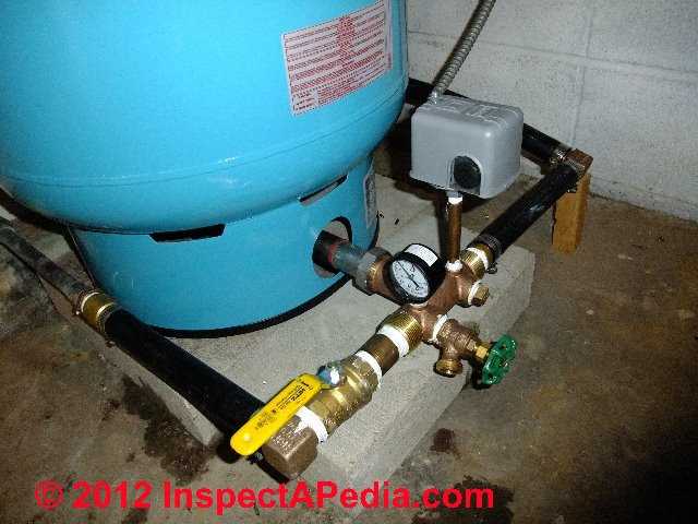
The water pump pressure control switch in the photo above (gray box mounted atop the water piping at the bottom of the pressure tank) and the pump relay switch (green labeled box in the photo below) are two different devices.
As we explain below, all well pump systems require a pressure control switch to sense the water pressure and turn the pump on and off as needed.
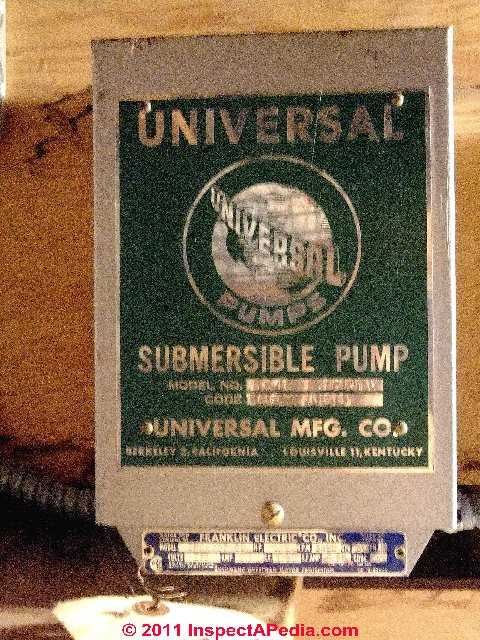
But when a higher horsepower submersible pump is used, a separate pump relay (red arrow in photo below right) is used to actually control turning the pump on and off.
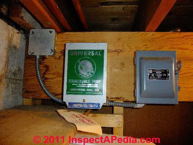
Well Pump electrical power switch: In the photo at above right, you'll note a third control marked by the white arrow. This is the main electrical power shutoff for the well pump.
Some pump relay covers, when removed, include a pull-out switch that cuts electrical power to the pump.
This is a handy detail to know: if your well pump relay switch is of that type, and if the cover of the switch is not securely installed, your well pump could lose electrical power and the building will have no water.
Watch out: while the pressure control switch is usually easy to find (located on or close to the water pressure tank) the pump relay switch might be found nearby, say on a wall (photo below left) or it might be hidden away in a closet or crawl space (photo above right).

How to Recognize and Locate a Pump Relay Switch
In this photograph a pump relay switch is mounted on the wall to the left of the blue water pressure tank. You'll notice that an electrical conduit can be seen running down the wall below this gray switch box. The relay is usually mounted on a wall near the water pressure tank.
How are Water Pump Relay Switches Wired & Controlled?
Electrical power, either 120V or 240V, is brought into the relay switch from the electrical panel and is connected to one side of an internal relay switch inside the box.
Wiring to the water pump, usually a submersible pump located inside the well, is connected to the other side of the relay switch.
A separate pair of wires will run from the relay switch to the pump pressure control switch. (See that little gray box at the lower end of the conduit below the larger, wall-mounted gray pressure switch box?).
When the pump pressure control switch detects that the water pump should turn on, a light-duty switch inside of the water pump pressure control switch senses this pressure drop and turns on the heavy-duty electrical relay switch inside of the wall mounted pump relay.
The wall mounted relay thus is sending power to the water pump.
When do we use a pump relay switch
A pump relay switch such as the relay switches shown in photographs in this article is used to power a water pump when the voltage/amperage combination would be too much to switch on and off by the simple pump pressure switch.
Larger horsepower submersible well pumps draw more than 15A, sufficient amperage that if they were wired through a little pressure control switch at the water tank that switch would burn up pretty quickly.
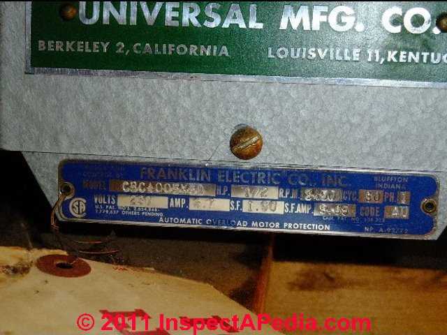
The specifications and load handling capacity of the pump relay switch are found on the switch cover or body, or sometimes on a sticker located inside the switch cover.
A closer examination of this data (above right, click to enlarge) indicates the horsepower rating of the pump that the switch is intended to handle - in the case of our photo, it's a 1/2 hp submersible well pump wired for up to 230V (and at 5this voltage drawing just 7.7Amps).
Technical note: if the well pump offers the option of wiring at either 120V or 240V, we prefer to wire for 240V service. If you need help sorting out the definitions of current (amperage or amps), voltage, and watts, see DEFINE AMPS VOLTS WATTS.
When are pump relay switches not used?
Many well pump installations use only the pressure control switch to operate the system, so separate pump relay switches are not installed on every water pump.
Separate pump relay switches are usually not found when the water
pump is above ground such as when a one line or two line jet pump is installed at or near the water pressure tank and they are generally not used on smaller horsepower submersible well pumps that draw 15A or less of current. For those installations,
a WATER PUMP PRESSURE CONTROL SWITCH is sufficient.
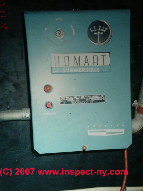
Combined Heavy Duty Pump Relays and Pressure Controls
Some heavy duty submersible pump relays such as the Homat™ switch shown in this photograph combine the pressure control sensor and the heavy duty pump electrical relay switch.
Notice the copper tube entering the pump relay box at the lower right in this photo? Also notice that this switch has a pressure gauge right on the switch box face.
This pump control switch has combined a water pressure sensor and switch with the relay to send power to the water pump.
So inspecting the rest of the water equipment at this building we won't expect to find that ordinary littlegray box which controls pump operation on a lower horsepower water pump.
Where is the "electrical ON-OFF switch" when a wall mounted heavy duty pump relay is installed?
We may not see a separate wall mounted electrical switch by the pump controls when a heavy duty relay such as those discussed here is installed.
Rather, on at least some of these switches, pulling off the cover of the relay box will actually disconnect internal components and thus serves as a local electrical switch for the water pump.
Watch out: Safety warning live voltage is inside of all of these pump switches - and is a shock hazard.
When you don't see an ordinary wall switch to turn off the water pump you're probably safer going to the electrical panel where you can turn off power to the water pump by switching off the appropriate circuit breaker or pulling the appropriate fuse.
...
Reader Comments, Questions & Answers About The Article Above
Below you will find questions and answers previously posted on this page at its page bottom reader comment box.
Reader Q&A - also see RECOMMENDED ARTICLES & FAQs
Power devices for a submersible well pump
I have a question about power devices for a submersible well pump. The new system I am installing is a 40ft deep low producing well with a 1/2hp 230v 6amp max submersible pump, with a controller.
This will fill a cistern with 2 level sensors. From the cistern the water has a pressure pump and pressure tank.
What size type of a pump contactor do I need to use for the level sensors signal to the pump controller? Or should I use something else?
Thanks . On 2024-08-12 by Dan
Reply InspectApedia Publisher (mod)
@Dan,
Thank you for an interesting question, I'll enjoy doing some figuring with you.
I've installed and repaired some systems like the one you described and inspected others. In part, choosing the pump contactor for your local pump and pressure tank is probably very straightforward.
You would use a typical water pressure switch like those described in this article series. When pressure in your local pressure tank drops to the cut-in point the pump turns on and draws water from the cistern. Etc..
I am guessing that the two level switches in your cistern are being used
1 to turn on and off your remote pump to refill the cistern
2 and perhaps you're using a second level switch to prevent the local pump from turning on at all if the level in the cistern has fallen too low
But I need you to clarify that by telling me a bit more about your design.
Followup by Dan
@InspectApedia Publisher, Yes, let me clarify. The 1/2hp, 230v, 6amp submersible pump in the 40ft well is what I need the contactor for.
The level sensors in the cistern will communicate to the contactor via a B/W series relay to energize power to the pump controller when low water in the cistern and to de energize when filled.The submersible pump comes with its own controller. It is the contactor I am needed the help sizing. It is not high amps or hp as it is lifts 40ft and may produce a 1/2 to 1 gpm. I have only seen submersible pumps set up this way.
Should it be wired without a contactor?
I don't see contactors less than 20amps.
Thank you for insight and help.Reply by InspectApedia Publisher (mod)
@Dan,
In the installations that I'm familiar with and that are similar in design to yours, since the contractor is not an overcurrent safety device, a 20 amp rated contactor would work perfectly well even though your pump is only a 6 amp motor.
A related question is the distance is involved. If you have a very long wire run to your pump you may want to use a larger size (eg #12) wire even though your pump would normally run on a 15 amp circuitComment by Dan
@InspectApedia Publisher, very good, I was hoping my thinking was in line. The distance from the pump controller to the submersible pump in the well casing is 70ft. 12awg is the wire set planned from the pump to the controller, contactor, float switch and panel breaker.
Also there will be a pumpsaver device for the submersible along with a grit spin down filter and a dole restriction with a globe valve to throttle the incoming gpm to match the aquifer recharge. Pressure relief for the pressure pump on the other side of the cistern
I really like B/W controls I have them on a much larger system of mine for 40yrs without a single issue. I am enjoying reading all the information on this site. Thanks 👍 Dan
No electrical power coming out of new pump relay
Can you possibly answer this for me. A brand new relay was installed on our pump. There is power going in but no power coming g out according to the guy that installed it. What could possibly be the problem? I haven't even gone to look at it yet.so I don't even know what brand it is . I figure I'd best be prepared before going down to where it at if at all possible. Can you help? On 2023-10-09 by Tom Coffey
Reply by InspectApedia DF (mod)
@Tom Coffey,
If a competent electrician or installer tested and confirmed proper voltage at the line-in terminals on your pressure control switch/relay, then you would find "power going out" only when the switch contacts are closed - that is, when pressure drops enough that the switch closes in an effort to turn on the pump.
If then we turn on water in the building and see pressure falling in the system but the switch never responds by closing the contacts, then it's possible that it's not mounted properly or the tubing or pipe nipple bringing water pressure to the switch is clogged.
Or possibly the switch is not wired correctly.
Let me know what you find when you see the installation.
Watch out: if an installer is not familiar with proper electrical wiring someone could be shocked or killed.
Is there a diagram for wiring an on/off switch for a pump?
Is there a diagram for wiring an on/off switch for a pump?
I'm not looking for a power switch wiring diagram, instead I would like to install an on/off switch to control to power between 2 pumps. I have seen several diagrams with such an option however I cannot find a diagram that shows how to wire this type of switch anywhere on the internet On 2022-04-10 by Anonymous
I
Replyby Inspectapedia Com Moderator (mod)
@Anonymous,
A simple wall switch such as an electric light switch set in an electrical box and with a proper switch plate should be perfectly suitable for a 120 volt pump. If it's a 240-volt pump then you need a double pole switch. You'll find electric light switch wiring diagrams at this website by searching for
LIGHT SWITCH WIRING DETAILS - click this link
My water pump won't start
Water pump not starting On 2018-05-07 09:01:08.565075 by Javed ahmad M
Reply by danjoefriedman (mod)
Javed
Sure, we're glad to help. If your pump won't start, see the diagnostics at
WATER PUMP WON'T START
...
Continue reading at PUMP CONTROL STATUS INDICATORS or select a topic from the closely-related articles below, or see the complete ARTICLE INDEX.
Or see WATER PUMP RELAY CONTROL SWITCH FAQs - questions & answers posted originally at this page.
Or see these
Recommended Articles
- CHATTERING RELAY CONTROL SWITCHES
- WATER PRESSURE LOSS DIAGNOSIS & REPAIR
- WATER PUMP INTERMITTENT CYCLING - pump runs occasionally for no reason
- WATER PUMP PRESSURE CONTROL SWITCH - installation, adjustment, troubleshooting & repair of well or water pump control switches.
- WATER PUMP PRESSURE SWITCH NOISES - clicks, hums, buzzes at the pressure control
- WATER PUMP PRESSURE SWITCH REPAIRS - home
- WATER PUMP RELAY SWITCH - 240V pump switch
- WATER PUMP SHORT CYCLING - pump turns on & off too frequently
- WATER PUMP WIRING REPAIR
Suggested citation for this web page
WATER PUMP RELAY SWITCH at InspectApedia.com - online encyclopedia of building & environmental inspection, testing, diagnosis, repair, & problem prevention advice.
Or see this
INDEX to RELATED ARTICLES: ARTICLE INDEX to WATER SUPPLY, PUMPS TANKS WELLS
Or use the SEARCH BOX found below to Ask a Question or Search InspectApedia
Ask a Question or Search InspectApedia
Questions & answers or comments about the function, diagnosis, repair or replacement of well pump relay switches & controls
Try the search box just below, or if you prefer, post a question or comment in the Comments box below and we will respond promptly.
Search the InspectApedia website
Note: appearance of your Comment below may be delayed: if your comment contains an image, photograph, web link, or text that looks to the software as if it might be a web link, your posting will appear after it has been approved by a moderator. Apologies for the delay.
Only one image can be added per comment but you can post as many comments, and therefore images, as you like.
You will not receive a notification when a response to your question has been posted.
Please bookmark this page to make it easy for you to check back for our response.
IF above you see "Comment Form is loading comments..." then COMMENT BOX - countable.ca / bawkbox.com IS NOT WORKING.
In any case you are welcome to send an email directly to us at InspectApedia.com at editor@inspectApedia.com
We'll reply to you directly. Please help us help you by noting, in your email, the URL of the InspectApedia page where you wanted to comment.
Citations & References
In addition to any citations in the article above, a full list is available on request.
- Access Water Energy, PO Box 2061, Moorabbin, VIC 3189, Australia, Tel: 1300 797 758, email: sales@accesswater.com.au Website: http://www.accesswater.com.au/
Moorabbin Office: Kingston Trade Centre, 100 Cochranes Rd, Moorabbin, VIC 3189
Australian supplier of: Greywater systems, Solar power to grid packages, Edwards solar systems, Vulcan compact solar systems, water & solar system pumps & controls, and a wide rage of above ground & under ground water storage tanks: concrete, steel, plastic, modular, and bladder storage tanks. - Grove Electric, Typical Shallow Well One Line Jet Pump Installation [PDF], Grove Electric, G&G Electric & Plumbing, 1900 NE 78th St., Suite 101, Vancouver WA 98665 www.grovelectric.com - web search -7/15/2010 original source: http://www.groverelectric.com/howto/38_Typical%20Jet%20Pump%20Installation.pdf
- Grove Electric, Typical Deep Well Two Line Jet Pump Installation [PDF], Grove Electric, G&G Electric & Plumbing, 1900 NE 78th St., Suite 101, Vancouver WA 98665 www.grovelectric.com - web search -7/15/2010 original source: http://www.groverelectric.com/howto/38_Typical%20Jet%20Pump%20Installation.pdf
- In addition to citations & references found in this article, see the research citations given at the end of the related articles found at our suggested
CONTINUE READING or RECOMMENDED ARTICLES.
- Carson, Dunlop & Associates Ltd., 120 Carlton Street Suite 407, Toronto ON M5A 4K2. Tel: (416) 964-9415 1-800-268-7070 Email: info@carsondunlop.com. Alan Carson is a past president of ASHI, the American Society of Home Inspectors.
Thanks to Alan Carson and Bob Dunlop, for permission for InspectAPedia to use text excerpts from The HOME REFERENCE BOOK - the Encyclopedia of Homes and to use illustrations from The ILLUSTRATED HOME .
Carson Dunlop Associates provides extensive home inspection education and report writing material. In gratitude we provide links to tsome Carson Dunlop Associates products and services.


