
InspectAPedia®FREE Encyclopedia of Building & Environmental Construction, Diagnosis, Maintenance & Repair |
Question? Just ask us! InspectAPedia
|
 Deflection Limits in Wood Structures
Bending & Deflection Limits in Beams, Rafters, Joists, Floors, Posts etc.
- POST a QUESTION or COMMENT about deflection, sagging, bending limits in building structures
What are the recommended limits of bending, deflection, or sagging in building structures or components like beams, girders, roof rafters, or floor structures?
How do we actually measure the amount of sag in a beam, roof, or floor?
How do we compare our measured amount of sagging or deflection with the recommended or allowable deflection standards found in building codes?
This article series describes the construction, inspection, repair of wood and other structures and provides links to codes & standards for such work.
InspectAPedia tolerates no conflicts of interest. We have no relationship with advertisers, products, or services discussed at this website.
- Daniel Friedman, Publisher/Editor/Author - See WHO ARE WE?
Beam Deflection
[Click to enlarge any image]
The wood beam shown here is from an eighty-year old building in an earthquake zone. The owner was concerned about the checking cracks in the beam. Below we give typical standards for allowable deflection - or bending or sagging in various types of structural components.
Watch out: When a wooden beam is failing from rot, insect damage, or excessive loading, it may also split but you'll see that the split is very different, showing visible breakage of wood fibers and sagging in the span of the beam.

Above: there is a bit of sag and some checking in the wood beam above the yellow arrow in our photo.
A closer look will be needed to see if this beam is actually failing. In wood-framed structures, leaks, rot, and insect damage play important roles in the failure of wooden structural members.
7 Easy Steps to Measure Deflection in a Beam, Floor, or Roof
 Here we outline steps that even an amateur can take to measure the bend, sag, or more technically, deflection in a beam, roof, or floor, and then to compare that with typical allowable deflection given in building standards.
The essential concept used to measure beam sagging is to draw or create a level, horizontal line, such as using a string and level, that then allows measurements from the level line to the underside of the beam, roof, or down to a sagging or deflected floor surface.
By making a series of measurements you can confirm the location of the lowest point in the sagging beam - usually at the center of its span - and you can measure the amount of sag - by comparing your lowest point distance to the highest point distances at the supported ends of the beam.
Then simple arithmetic will let you compare your measurement of sagging with typical building deflection standards.
If you need to measure the deflection in a vertical building component such as a wall or roof, use the similar procedure we give
- Set a Level Reference Line
Establish a level measurement line directly below the beam whose sagging you want to measure.
If you're measuring a sagging roof, establish a level measurement line below the center of span of the roof slope - most likely to be its lowest point
If you know that the floor surface below the beam is dead flat and dead level, then you can use that as your level line, otherwise you'll want to use a string line, drawn tight so that the string doesn't sag, and fastened at either end to a wall or post below the beam in question.
The distance below the beam to your level string line can be any convenient distance for making the additional measurements below.
We use a string and a four foot level to get our level line. You can try using a little line level that hangs onto the string but in our OPINION that's not so accurate. - Measure Beam to Reference Line = Probable Sag
Measure & record the distance between the underside of the beam and the top of the string, at the center of the beam - in inches or centimeters (cm).
Find the beam's center by measuring its length wall-to-wall or post-to-post, and then divide that number in half. Mark the center of the beam's underside with a pencil or small nail.
That point is probably the lowest point in the sag or deflection.
Example: we measure 33 1/2" from the under side of our beam to the top of our horizontal string line below the beam.
Let's call this
Center Sag Distance or CSD = 33.5"
- Confirm Lowest Point of Deflection
Measure & record the distance between the underside of the beam and the top of the string at one foot intervals- in inches or cm - in both directions away from the center, sufficient to confirm that the center measurement you selected in Step 2 is actually the lowest point.
Example: at every measurement point to either side of our CSD measurement point (Step 2), it is a larger number such as 33.6" then 33.8", etc.
Then we can conclude that the measurement we made at Step 2 is the maximum deflection or actual deflection of the beam.
- Measure Beam End Distances to Level Line
Measure & record the distance between the underside of the beam and the top of the string at each end of the beam - in inches or cm.
If the original beam construction was level and if your string was set dead level, then the end distance measurements at the two beam ends should be the same.
Watch out: if the end measurements from beam to string are different, double-check that your string line is truly level and if it's not, re-level the string and go back to Step 2.
Example: if at each end of the beam we measured a distance from beam to string of 33" then
we'll call this
Beam End Distance or BED = 33"
- Calculate the Actual Beam Deflection
Subtract the distance beam-to-string measured at center of sag CSD (Step 2) from the distance of beam-to-string measured at either end of the beam BED (Step 4) .
Example: if the measured CSD = 33.5 "and the BED was 33"
Record this distance 33.5 " - 33" = 0.5"
CSD - BED = AD or Actual Deflection = 0.5"
- Measure Actual Beam Length
Measure and record the beam span or Actual Length = total unsupported length of the beam (or roof or floor) - in inches or cm
Example: we measure the unsupported length of our beam as 12 ft 6 inches between the inner faces of its supporting posts or walls.
Watch out: make this beam length measurement as the true horizontal distance between its two supported ends.
Don't measure the beam length by placing your tape directly against the upper or under side surfaces of the beam because for beams that sag, that distance will be longer. You'll be measuring the length of an arc rather than of a straight line.
Really? Well yes. Since a beam doesn't "grow" in length after it's installed, if it sags, the distance between its ends is actually a bit shorter. But that length loss is probably not visible as it will be hidden atop the outside edges of the supporting posts.
And as we said just above, if we measure along the sagged arc surface of a beam, that distance will be longer than the level horizontal distance between the supporting posts or walls below the beam.
So we are going to measure the horizontal distance between the inner faces of the two supporting walls or posts below the beam - a more consistent number if we can assume for now that the building walls or the beam's supporting posts are themselves still true or vertical.
Example: we measure the distance between the two supporting posts or walls below our beam and find that the actual length = 12'6"
If our actual beam were 12'6" in unsupported length, its total length in inches would be (12' x 12"/ft) + 6" = 144+6 = 150"
Actual Length = AL = 150"
- Compare Actual Deflection AD with the Permissible Deflection PD Standard for the Actual Beam Length
Permissible Deflection standards are typically numbers like PD = L / 360
In plain English, this means that the permissible deflection of a beam is its unsupported length L / 360.
That is to say, the allowable or permissible deflection in the beam = Unsupported Beam Length L divided by 360
If the measured unsupported length of a beam were 360 inches long our Permitted Deflection would be PD = 360" / 360" = 1"
A more stringent deflection standard that allows less sagging will use a bigger divisor. For example, for a roof supporting a plaster ceiling, the allowable sag may be L /480.
Since there's almost no chance that our beam length or roof rafter run or floor joist length is going to be exactly 360" or 480" or any of the other deflection standard numbers, let's see how we use our actual measurements using our example measurements given in Steps 1-6 above.
Permitted Deflection PD = Actual Length / Deflection Standard -Length
Example using the deflection standard L/360,
For our 150" beam, we substitute our Actual Length of 150" for "L" to find the permitted deflection:
Permitted Deflection PD = AL / 360 = 150" / 360" = 0.41" below level
Finally, let's compare PD the Standard or Permitted Deflection for our beam with AD, the actual measured deflection or sag amount that we measured in Step 4 and calculated in Step 5 above.
ADMeasured = 0.5"
PD Standard = 0.41"
Conclusion: Since AD > PD, our beam has more sag than is permitted by or recommended by the L/360 standard.
Checking Cracks in a Sagging Beam Supporting a Roof
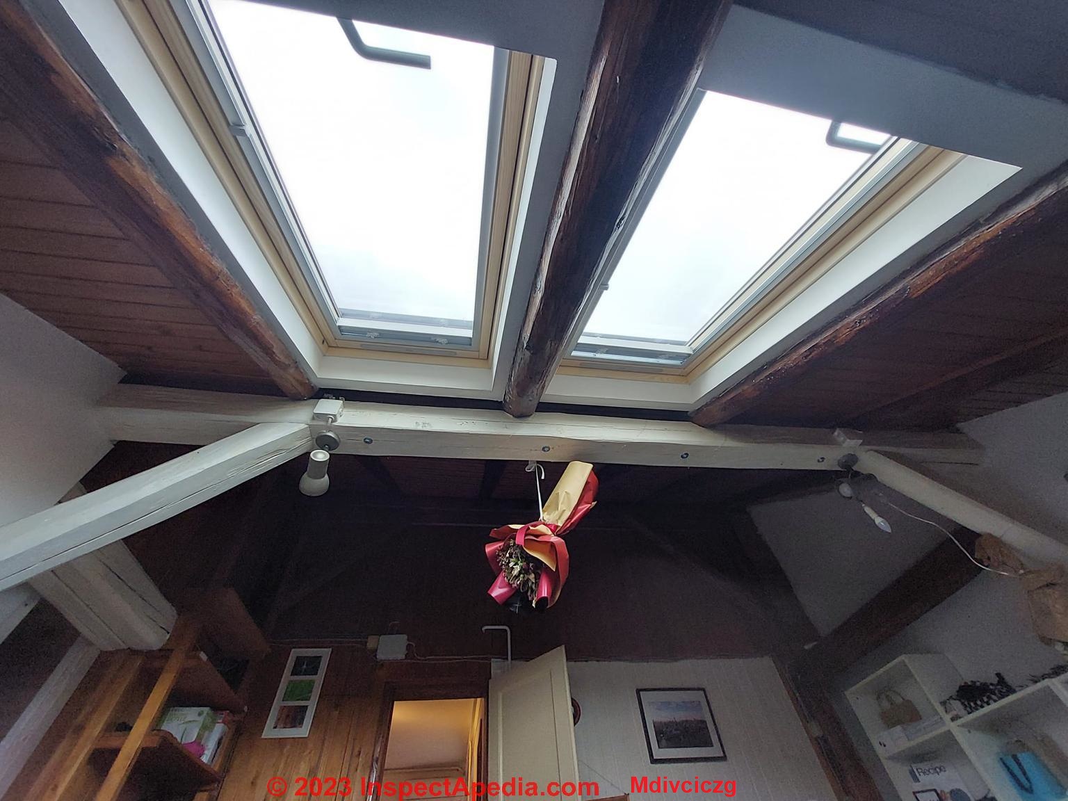
On 2023-03-11 by Mdivciczg
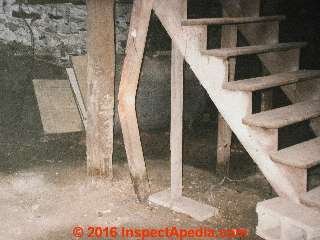
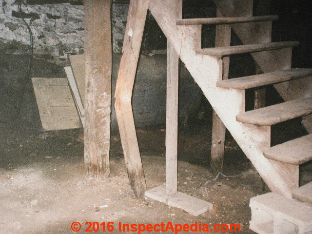
Hi i have a loft (roof) apartment, with cracked wooden beams supporting the structure. We had a big earthquake and multiple (800 smaller ones, really)earthquakes afterwords.
Before the beams did have cracks in the middle but they were thinner last year. A structural engineer came and ordered some reinforcement of this white beam(bolts underneath it).

It's wide cracked all along one side , on the other side there is also a thin crack across the length. On the bottom as well. The support studs also have a thin crack now.
So left, right, and bottom.
Please i would very much appreciate your opinion and advice.
I know cracking is normal, but there must be a safety limit. Thank you in advance.
On 2023-03-12 by InspectApedia Editor (mod)
@Mdivciczg,
Thanks for the beam checking crack and possibly beam sagging or bending photo and question. We think those are probably two separate questions:
Checking cracks in posts and beams ?
Checking cracks are normal, even when rather wide and long as in the beam in your photo. The chief time that those cracks raise a concern are if the crack happens to cross the path of a structural connector such as a bolt - that might weaken the connection.
If you inspect the crack more closely you'll see that these checking cracks may be quite deep, but they never pass all the way through a beam or post.
As we elaborate below, the checking or splits in that beam would not be the result of earthquake movement and would be very hard to blame on an earthquake that made not one iota of other detectable damage or movement in the building and its structural components.
See details at CRACKS CHECKS SPLITS in BEAMS, LOGS & POSTS
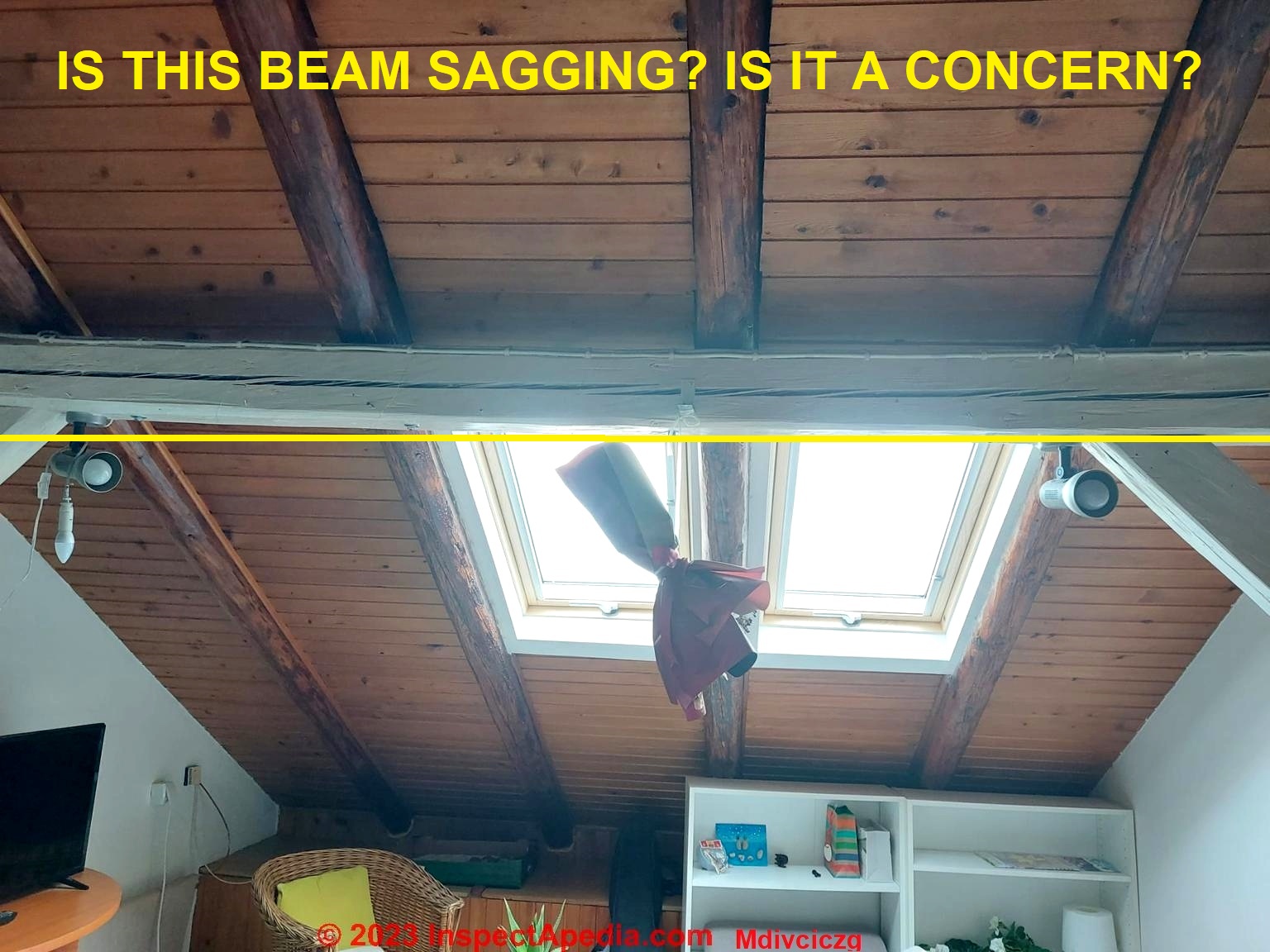
Is the beam sagging? Is the sagging acceptable or is it a problem?
I think that your photo may have been taken with a bit of a wide-angle setting, so I'm not sure if the apparent beam sag I see in the photo is real or not.
IF the beam is sagging that can be measured and evaluated, but from your own report, you've already had a structural engineer look at the beam and specify some reinforcmements, suggesting that either the beam was under-sized from original construction, or its structural connections were inadequate.
If the floor below is flat and level, measure the height from floor to beam at its center and at its ends. If those measurements are all about the same, then there is no significant sagging going on.
Above on this page we give example calculations for describing the amount of sag in a beam and comparing that sag to the deflection or sagging permitted by various standards.
To apply an accurate standard to the beam in your photo we
- Need to consider that this is a special design in which (apparently) the beam is replacing a normal rdige board with a much heavier member because, with the absence of horizontal rafter ties or ceiling joists below, the roof is in essence hanging or "suspended" from that center beam.
Almost none of the weight of the roof's live and dead loads would be borne by the walls - othewise the walls, absent any rafter ties or ceiling joists, would bulge outwards.
- Know the dimensions involved: the length of the beam's span and the measurement of any actual sag in the beam
- Compare the beam's dimensions and span with an engineer's or architect's calculation of the required beam size for the total roof size and weight of its live and dead loads
The required beam size for your building depends on at least these factors:
- the wood species
- the horizontal distance or span
- the live load - such as snow - which depends on where the building is located
- the dead load - weight of the roof system itself
- applicable building codes where you live
Absent ALL of that information, a vague arm-waving ballpark guess might be that if the beam is sagging noticeably, (I'm not a structural engineer but am experienced with this topic) then the beam could be under-sized for the roof load it carries. The sagging would be due to its size, and not much due to the normal checking cracks that occur when a beam dries.
Typical roof beam deflection standards and texts give these Deflection Standards
The deflection in case of nailed laminated beams, joists, purlins, battens and other flexural members supporting brittle materials like gypsum, ceiling slates, tiles and asbestos sheets shall not exceed 1/480 of the span or in some standards 1/360 of the span.
For roofs, in general, the maximum allowable deflection is L/180 (or 0.55 percent of the span L)
Or for roofs supporting a plastered ceiling, L/360. This is also a Canadian standard.
The illustration, courtesy of Weyerhaeuser weyerhaeuser.com/ gives some other common allowable deflection limits such as 1/240 for "all other structural members".

Excerpt from the Indian deflection standard listed below on this page:
5. Design Considerations
5.1 Nailed laminated beams shall be designed in accordance with IS 883-1966, Code of Practice for design of structural timber in building (second revision) (since revised).
5.2 Deflection -
The deflection in case of nailed laminated beams, joists, purlins, battens and other flexural members supporting brittle materials like gypsum, ceiling slates, tiles and asbestos sheets shall not exceed 1/480 of the span.
The deflection in case of other flexural members shall not exceed 1/360 of the span in case of beams and joists and 1/225 of the freely hanging length in case of cantilevers.
Earthquake Damage vs. Sagging Beams?
Earthquake movement of buildings, regardless of whether it's vertical or horizontal, would not produce checking cracks in a beam and certainly would not be able to damage just one solitary building structural member in isolation, without a shred of evidence of movement or disturbance throughout the rest of the structure?
Watch out: you mention that the building has been exposed to significant earthquake activity.
Even when a building appears to be still standing and not showing obvious signs of dangerous structural collapse, there can be subtle but important safety concerns at any building subjected to earthquake or similar disturbances, such as risk of fire or explosion from gas leaks, electrical hazards, plumbing leaks, failures, water damage, mold damage, and structural concerns such as disturbance of foundations or of structural connections.
An expert and comprehensive building inspection to look for damage or unsafe conditions would be in order if you have not already had this done.
On 2023-03-13 by Mdivciczg
Hi, I just want to thank you truly for this detailed reply. It really helpful I've been terribly worried. I was planning to put gypsum board and isolation rockwool to close the wood.
Then I calculated approximately that that would add about 200-300 kilos.
It's just seems concerning that I just add this weight to a beam that already looks slightly slanted and cracked. Might not be safe even in these conditions.
The handyman told me it fine but how many cracks is fine (on all 4 sides), with apparent visual sag.?The beam picture isn't under a wide angle. I made sure.
Thanks you so much. I just wasn't sure if I should be worried. Here's another image of other side of beam and side beems.
I really needed an expert opinion. Already 3 handyman have told me it is fine.
One that seemed knowledgeable told me that that bolting didn't do actually much. That it should be reinforced. So didn't know what to do.
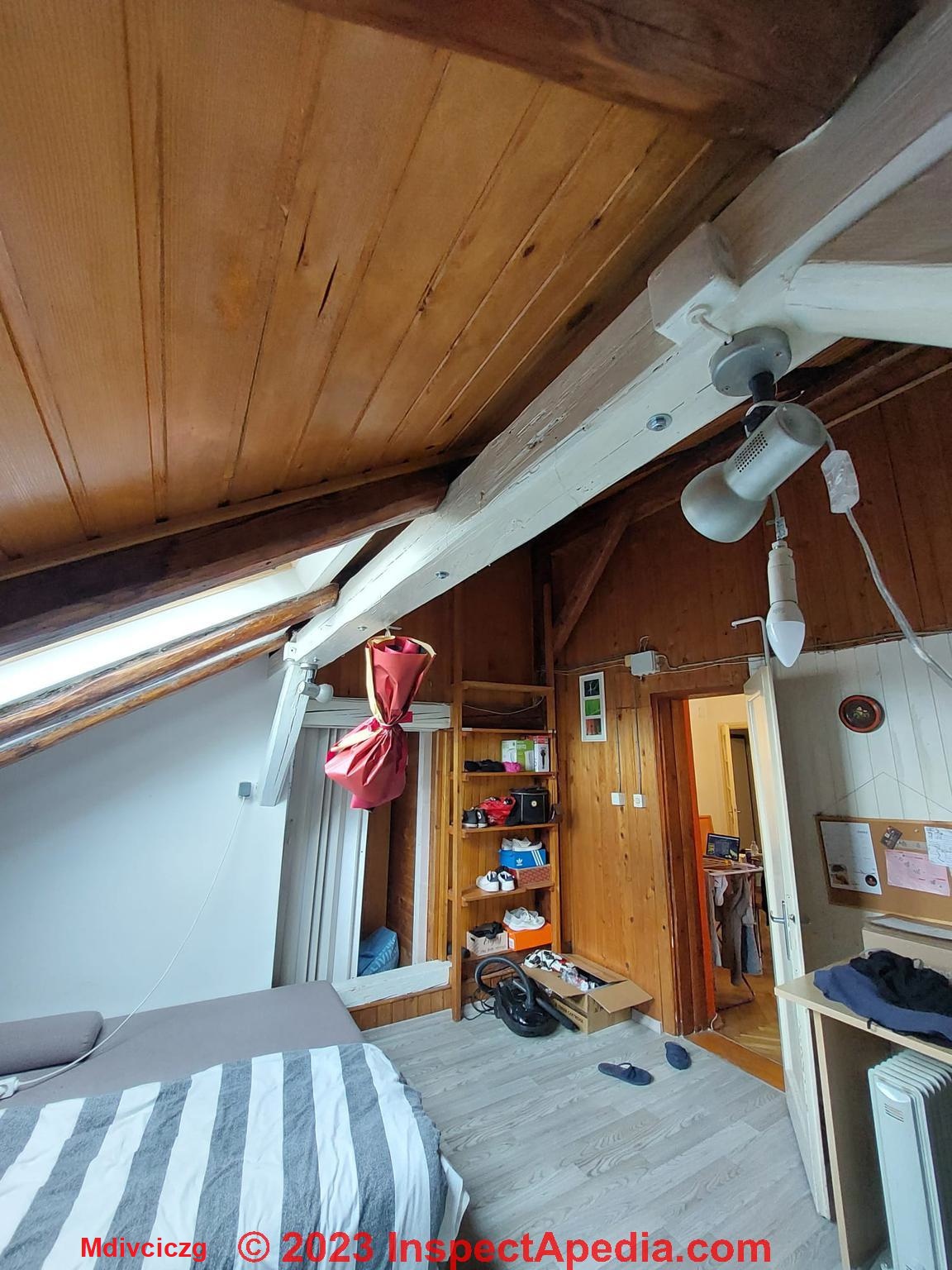
I just wanted to add, the beam has insect worm damage (small holes).and is about 80 years old. Thanks you.
Picture beam
On 2023-03-13 by InspectApedia Publisher (mod) - evaluate beam damage from insects?
@Mdivciczg,
On an older home tiny holes in wood members are often a sign of powder post beetles or old house borer beetles. If they're active you'll usually find wood dust around the openings.
We probe such beams or posts to estimate the extent of damage; if it's quite superficial and if there are no signs of insect activity, there's not much to be done.
See
POWDER POST BEETLES
Watch out: if the beam to post connections in your home are questionable, you should certainly have them examined by an experienced post and beam framer or a structural or civil engineer.
Unlike conventional wood stud and rafter framed buildings, there is not redundancy among structural members when a central beam supports a suspended roof - which appears to be the design we see in your photos.
So every connection is critical.
Research & References on Allowable Limits on Beam Deflection
[More structural component deflection standards & details in process - contributions are invited]
- Britain, BS 8110, Deflections, - 2023/03/12 original source: https://www.structuralguide.com/deflection-of-beams-and-slabs/
Excerpt:
BS 8110 mainly concern about limiting the span over effective depth ratio to maintain the deflection within the allowable limit. BS 8110 Part 1 provides a Table indicating the limiting values of the deflections. The following values could be considered for the beams and slabs as allowable span over effective depth ratios.
Support Condition - Rectangular Section
Cantilever - 7
Simply Supported - 20
Continuous - 26
If the span is greater than 10m, span over effective depth shall be multiply by “10/Span” which a modification factor. This factor shall not be applied for cantilevers and it shall be checked by calculations.
The allowable span depth ratio shall be modified by the factors for tension and compression reinforcements. - Canada: STRUCTURAL DEFLECTIONS [PDF] from the Canadian Roofing Contractors Association CRCA, retrieved 2023/03/12, original source: https://roofingcanada.com/wp-content/uploads/2018/05/Volume-07-Deflections.pdf
- CI. 5.2 of IS 4983:1986
- Holmes, Alan,
Performance of timber under changing environments
,Alan Holmes, Building Surveyor, Nov. 2017
Does Normal Wood Beam Checking Affect Sagging Deflection Performance?
Abstract
A common problem is deflection in timber purlins and beams. However, sometimes things are not as straight forward as first thought. In this paper the author considers how the environment of a building can affect the performance of timber members.
Cites:
R M Higgins Fact sheets – 2. Recovering Old Timber Roofs 6.Structural Timbers and 13d. Sagging Lintels Marley roofing guidelines – Web site
The Building Regulations Approved Document F2 BS 5250 the Code of practice for the control of ventilation in buildings.
Defects and Deterioration in Buildings – Author, Barry A Richardson published by E & F N Spon
- Indian Standard For Code Of Practice For DESIGN AND CONSTRUCTION OF NAILED LAMINATED TIMBER BEAMS, Reprint August 1983 - Indian Standards Institution Manak Bhavan, 9 Bahadur Shah Zafar Marg New Delhi 110002 - retrieved 2023/03/12, original source: https://law.resource.org/pub/in/bis/S03/is.4983.1968.pdf
- International Residential Code, IRC Table R301.7 Allowable Deflection of Structural Members
- International Standard, IS: 4983 - 1968, 1978, reaffirmed 2010
- STEEL PURLINS, RAILS, BEAMS - DEFLECTION - Steadmans [PDF]
Steadmans provides similar details about construction standards and allowable deflection in steel purlins, rails, and beams:
- Weyerhaeuser: Wood Products, how to easily calculate allowable deflection, Sept. 1, 2002 in Wood Products -
weyerhaeuser.com/blog/how-to-easily-calculate-allowable-deflection/#:~:text=Maximum Allowable Deflection&text=Allowable deflection is generally expressed, in ft divided by 360
...
Continue reading at BULGE or LEAN MEASUREMENTS or select a topic from the closely-related articles below, or see the complete ARTICLE INDEX.
Or see these
Recommended Articles
- BULGE or LEAN MEASUREMENTS
- CRACKS CHECKS SPLITS in BEAMS, LOGS & POSTS
- DECK BEAM CONSTRUCTION
- FRAMING DAMAGE, INSPECTION, REPAIR - home - advice on looking for damaged, unsafe wood structure framing
- ROOF FRAMING TIES & BEAMS - home
- ROT, TIMBER ASSESSMENT
- STRUCTURAL WOOD ASSESSMENT
- WOOD BEAM VISUAL INSPECTION
- WOOD BEAM LOG VIGA CRACK REPAIR METHODS
- WOOD FLOOR DAMAGE REPAIR
- WOOD STRUCTURE ASSESSMENT - home
Suggested citation for this web page
DEFLECTION in WOOD BEAMS ROOFS FLOORS at InspectApedia.com - online encyclopedia of building & environmental inspection, testing, diagnosis, repair, & problem prevention advice.
Or see this
INDEX to RELATED ARTICLES: ARTICLE INDEX to BUILDING STRUCTURES
Or use the SEARCH BOX found below to Ask a Question or Search InspectApedia
Ask a Question or Search InspectApedia
Try the search box just below, or if you prefer, post a question or comment in the Comments box below and we will respond promptly.
Search the InspectApedia website
Note: appearance of your Comment below may be delayed: if your comment contains an image, photograph, web link, or text that looks to the software as if it might be a web link, your posting will appear after it has been approved by a moderator. Apologies for the delay.
Only one image can be added per comment but you can post as many comments, and therefore images, as you like.
You will not receive a notification when a response to your question has been posted.
Please bookmark this page to make it easy for you to check back for our response.
IF above you see "Comment Form is loading comments..." then COMMENT BOX - countable.ca / bawkbox.com IS NOT WORKING.
In any case you are welcome to send an email directly to us at InspectApedia.com at editor@inspectApedia.com
We'll reply to you directly. Please help us help you by noting, in your email, the URL of the InspectApedia page where you wanted to comment.
Citations & References
In addition to any citations in the article above, a full list is available on request.
- In addition to citations & references found in this article, see the research citations given at the end of the related articles found at our suggested
CONTINUE READING or RECOMMENDED ARTICLES.
- Carson, Dunlop & Associates Ltd., 120 Carlton Street Suite 407, Toronto ON M5A 4K2. Tel: (416) 964-9415 1-800-268-7070 Email: info@carsondunlop.com. Alan Carson is a past president of ASHI, the American Society of Home Inspectors.
Thanks to Alan Carson and Bob Dunlop, for permission for InspectAPedia to use text excerpts from The HOME REFERENCE BOOK - the Encyclopedia of Homes and to use illustrations from The ILLUSTRATED HOME .
Carson Dunlop Associates provides extensive home inspection education and report writing material. In gratitude we provide links to tsome Carson Dunlop Associates products and services.
 |
HOME | ABOUT | ASK a QUESTION | CONTACT | CONTENT USE POLICY | DESCRIPTION | POLICIES | PRIVACY | |
| © 2026 - 1985 Publisher InspectApedia.com - Daniel Friedman | |||||||||