 Absorption Bed Septic Drainfield Design
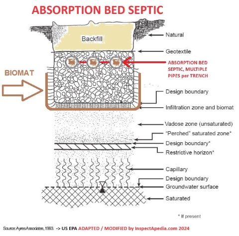
Mulitple effluent pipes per widened trench
- POST a QUESTION or COMMENT about absorption bed septic drainfield design
This article explains the design and construction specifications of an absorption bed septic leachfield or soakaway bed or drainfield.
Septic drainfields, also called leach fields, absorption beds, soil absorption systems, soakaway beds, and leaching beds, perform the functions of septic effluent treatment and disposal in onsite wastewater treatment systems, conventionally called "septic systems".
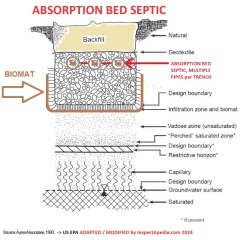
Page top sketch: shown again below as a larger image, an absorption bed septic field combines multiple effluent lines.
InspectAPedia tolerates no conflicts of interest. We have no relationship with advertisers, products, or services discussed at this website.
- Daniel Friedman, Publisher/Editor/Author - See WHO ARE WE?
Absorption Bed Septic Drainfield Systems
 Here we summarize the basics of an absorption bed septic drainfield design.
So what's the difference between a septic drainfield trench and a septic absorption bed?
An absorption bed system operates on a principal similar to the absorption trench except that several laterals, rather than just one, are installed in a single excavation.
This reduces the effective sidewall infiltration area per linear foot of lateral or leach line.
In the most common design of drainfield, perforated pipes are buried in gravel-filled trenches to form the drainfield.
[Click to enlarge any image]
This sketch shows a cross section of a typical drainfield trench, and places below the trench the critical biomat as well as other septic field design areas and considerations. (Source US EPA who in turn obtained the drawing from Ayres Associates, in turn modified by InspectApedia.)
a. Site Requirements for absorption bed septic system
(i) Percolation rate limits for absorption bed septic systems:
A bed system may be built in soils with a percolation rate between one and 30 minutes per inch.
A n absorption bed septic system shall not
be built where the soil evaluation indicates silty loam, clay loam, or clay.
(ii) Slope of the site of an absorption bed septic system shall not exceed eight percent.
(iii) Absoption bed septic systenm site shape:
Septic absorption bed systems are more practical on sites that are long and narrow with a minimal slope.
(iv) All absorption bed septic vertical and horizontal separation distance requirements shall be met.
b. Design Criteria for absorption bed septic systems
(i) Pressure distribution is required
for the installation of an absorption bed system.
The local health department having jurisdiction
may allow the use of siphon dosing on specific sites.
(ii) The maximum width of the bed of an absorption bed septic design shall be 20 feet.
The maximum length of each lateral from a pressure manifold shall be 100 feet.
Utilizing a
center manifold system, a bed may then have a maximum length of 200 feet.
Laterals for siphon dosing systems in beds are limited to 75 feet.
(iii) The depth of the septic effluent absorption bed
shall be between 18 and 30 inches below original ground level.
(iv) Absorption bed septic system laterals shall be spaced five (5) feet apart.
Two and one-half feet (2 1/2') must be provided between the laterals and the sidewalls. In the maximum width of 20 feet, only four laterals may be installed.
(v) Maximum dimensions for absorption bed septic effouent pressure distribution:
Using pressure distribution with a center manifold, a bed system shall have maximum dimensions of 205 feet by 20 feet.
(vi) The required septic effluent absorption bed bottom area
shall be calculated from the application rates shown in Table 5 - below
Table 5 - Absorption Bed Septic System Required Bottom Area
Table 5 - Absorption Bed Septic Bottom Area Size Required |
|
| Percolation Rate Min / Inch |
Application Rate Gal / Day / Sq.Ft. |
| 1 - 5 | 0.95 |
| 6 - 7 | 0.80 |
| 8 - 10 | 0.70 |
| 11 - 15 | 0.60 |
| 16 - 20 | 0.55 |
| 21 - 30 | 0.45 |
| >30+ | Not Acceptable |
Notes to the table above
Adapted from this original source: NYS Septic Design Code, Table 5, Absorption Bed Septic Systems -- Required Bottom Area
c. Materials Used for absorption bed systems
Absorption bed septic systems use essentially the same materials as found
at CONVENTIONAL SEPTIC LEACH FIELDS
d. Construction of absorption bed septic systems
(i) Heavy construction equipment shall be kept outside the proposed
bottom area of the bed.
Watch out: See warnings
at SHALLOW BED SEPTIC ABSORPTION TRENCH CONSTRUCTION
(ii) The required bed bottom area is excavated as level as practical.
(iii) The bottom and sides of the excavation are hand raked to reduce soil smearing.
(iv) After excavation, a six inch layer of aggregate is placed across the bottom of the bed.
(v) The laterals are laid level on the aggregate and covered with aggregate to a level two inches above the top of the pipe.
(vi) The entire bed area is covered with a permeable geotextile. Untreated building paper or a four inch layer of loose hay or straw may be substituted if a permeable geotextile is unavailable.
...
Continue reading at SEPTIC DRAINFIELD SHAPE or select a topic from the closely-related articles below, or see the complete ARTICLE INDEX.
Or see SEPTIC DRAINFIELD SIZE FAQs - reader questions & answers.
Or see these
Recommended Articles
- NEW YORK STATE 75-A.8 SUBSURFACE TREATMENT of EFFLUENT
- SEPTIC DRAINFIELD INSPECTION & TEST - home
- SEPTIC DRAWINGS
- SEPTIC SOIL & PERC TESTS
- SEPTIC SYSTEM DESIGN ALTERNATIVES - home
- SEPTIC SYSTEM DESIGN BASICS
- SEPTIC TANKS - home
- U.K. OFF-GRID SEPTIC REGULATIONS & SEWAGE SYSTEMS
- U.S. SEPTIC AUTHORITIES & DESIGN SPECIFICATIONS - Septic codes & regulations for each US State or Territory
Suggested citation for this web page
SEPTIC DRAINFIELD DESIGN - ABSORPTION BED at InspectApedia.com - online encyclopedia of building & environmental inspection, testing, diagnosis, repair, & problem prevention advice.
Or see this
INDEX to RELATED ARTICLES: ARTICLE INDEX to SEPTIC DRAINFIELDS & DBOXES
Or use the SEARCH BOX found below to Ask a Question or Search InspectApedia
Ask a Question or Search InspectApedia
Try the search box just below, or if you prefer, post a question or comment in the Comments box below and we will respond promptly.
Search the InspectApedia website
Note: appearance of your Comment below may be delayed: if your comment contains an image, photograph, web link, or text that looks to the software as if it might be a web link, your posting will appear after it has been approved by a moderator. Apologies for the delay.
Only one image can be added per comment but you can post as many comments, and therefore images, as you like.
You will not receive a notification when a response to your question has been posted.
Please bookmark this page to make it easy for you to check back for our response.
IF above you see "Comment Form is loading comments..." then COMMENT BOX - countable.ca / bawkbox.com IS NOT WORKING.
In any case you are welcome to send an email directly to us at InspectApedia.com at editor@inspectApedia.com
We'll reply to you directly. Please help us help you by noting, in your email, the URL of the InspectApedia page where you wanted to comment.
Citations & References
In addition to any citations in the article above, a full list is available on request.
- ASSE, PLUMBING DICTIONARY [PDF] 6th Ed., (2007) American Society of Sanitary Engineering, 18927 Hickory Creek Drive, Suite 220, Mokena IL 60448 USA Tel: 708-995-3019, Website: www.asse-plumbing.org
- NYS DOH, RESIDENTIAL ONSITE WASTEWATER TREATMENT SYSTEMS HANDBOOK [PDF] (2012) - original source: http://www.ongov.net/health/env/documents/DesignHandbook10_24_2
- WA DOH, BASIC PRINCIPLES of ONSITE SEWAGE [PDF] (1992) Washington State Department of Health, Office of Water, Washington D.C. USA
Also including as
APPENDIX A: WHY DO COARSE SOILS HAVE LARGER PORE SIZE & LESS SURFACE AREA? & WHY DO FINER SOILS HAVE SMALLER PORE SIZE & MORE SURFACE AREA
and
Cogger, Craig G., APPENDIX B: SEPTIC SYSTEM WASTE TREATMENT in SOIL, (1987) Washington State University Cooperatie Extension, EB1475, - [1] US EPA ONSITE WASTEWATER TREATMENT SYSTEMS MANUAL [online copy, free] Top Reference: US EPA's Design Manual for Onsite Wastewater Treatment and Disposal, 1980, available from the US EPA, the US GPO Superintendent of Documents (Pueblo CO), and from the National Small Flows Clearinghouse. Original source http://www.epa.gov/ORD/NRMRL/Pubs/625R00008/625R00008.htm Onsite wastewater treatment and disposal systems, Richard J Otis, published by the US EPA. Although it's more than 20 years old, this book remains a useful reference for septic system designers. U.S. Environmental Protection Agency, Office of Water Program Operations; Office of Research and Development, Municipal Environmental Research Laboratory; (1980)
- [2] "International Private Sewage Disposal Code," 1995, BOCA-708-799-2300, ICBO-310-699-0541, SBCCI 205-591-1853, available from those code associations.
- [3] "Manual of Policy, Procedures, and Guidelines for Onsite Sewage Systems," Ontario Reg. 374/81, Part VII of the Environmental Protection Act (Canada), ISBN 0-7743-7303-2, Ministry of the Environment,135 St. Clair Ave. West, Toronto Ontario M4V 1P5 Canada $24. CDN.
- [4] Manual of Septic Tank Practice, US Public Health Service's 1959.
- [5] "Installers Manual for Conventional Onsite Domestic Wastewater Treatment and Disposal Systems", Department of Environmental Conservation, Division of Environmental Health Drinking Water and Domestic Wastewater Program, Alaska Department of Environmental Conservation, 1 Aug 2000, Anchorage Offices, 555 Coredova, Anchorage AK 99501, Tel: 907-269-7500. retrieved 17 July 2012, original source: http://dec.alaska.gov/water/wwdp/onsite/pdf/Certified_Installer%27s_Manual.pdf [Copy on file as Alaska_Certified_Installer's_Manual.pdf].
Notice: [Quoting]
This document contains information regarding the installation of onsite sewer systems for single-family and duplex residences. It must be used by Certified Installers and homeowners who are subject to 18 AAC 72. Additional requirements are included in 18 AAC 72. If there is a conflict between the provisions of this manual and 18 AAC 72, 18 AAC 80, or other state regulations, the regulations language controls. AEDC offices.
The regulations cited above for Alaskans can be found at https://dec.alaska.gov/commish/newsroom/23-15-updated-onsite-wastewater-regulations/ - [7] Percolation Testing Manual, CNMI Division of Environmental Quality, PO Box 501304, Saipan, MP 96950
- [8] Test Pit Preparation for Onsite Sewage Evaluations, State of Oregon Department of Environmental Quality, Portland OR, 800 452-4011. PDF document. We recommend this excellent document that offers detail about soil perc tests, deep hole tests, safety, and septic design.
- [9] Wells and Septic System, Alth, Max and Charlet, Rev. by S. Blackwell Duncan, $ 18.95; Tab Books 1992.
- [17] Thanks to reader Michael Roth for technical link editing 6/29/09.
- [19] Septic Tank/Soil-Absorption Systems: How to Operate & Maintain [ copy on file as /septic/Septic_Operation_USDA.pdf ] - , Equipment Tips, U.S. Department of Agriculture, 8271 1302, 7100 Engineering, 2300 Recreation, September 1982, web search 08/28/2010, original source: http://www.fs.fed.us/t-d/pubs/pdfimage/82711302.pdf.
- In addition to citations & references found in this article, see the research citations given at the end of the related articles found at our suggested
CONTINUE READING or RECOMMENDED ARTICLES.
- Carson, Dunlop & Associates Ltd., 120 Carlton Street Suite 407, Toronto ON M5A 4K2. Tel: (416) 964-9415 1-800-268-7070 Email: info@carsondunlop.com. Alan Carson is a past president of ASHI, the American Society of Home Inspectors.
Thanks to Alan Carson and Bob Dunlop, for permission for InspectAPedia to use text excerpts from The HOME REFERENCE BOOK - the Encyclopedia of Homes and to use illustrations from The ILLUSTRATED HOME .
Carson Dunlop Associates provides extensive home inspection education and report writing material. In gratitude we provide links to tsome Carson Dunlop Associates products and services.

