 Conventional Septic Drainfield Design
Specifications / construction details

- POST a QUESTION or COMMENT about conventional septic drainfield design
This article and its tables explain the site, design, and materials criteria for the construction of a conventional septic drainfield.
We include tables that give a quick answer to how big the drainfield nees to be for various wastewater loads and soil percolation rates.
Septic drainfields, also called leach fields, absorption beds, soil absorption systems, soakaway beds, and leaching beds, perform the functions of septic effluent treatment and disposal in onsite wastewater treatment systems, conventionally called "septic systems".
InspectAPedia tolerates no conflicts of interest. We have no relationship with advertisers, products, or services discussed at this website.
- Daniel Friedman, Publisher/Editor/Author - See WHO ARE WE?
How large does a conventional septic drainfield need to be?
 A conventional septic tank performs roughly 45% of the sewage treatment or less at a private home served by a septic system.
The rest of the wastewater treatment and ultimately the liquid disposal occurs in the drainfield.
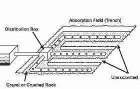
Sketch - USDA.
As you will read below, there is no one "right" septic absorption field size. Rather, the size needed (in square feet of area, presumably also unencumbered by trees, driveways, buildings, etc.) depends on several variables such as the rate at which the soil can accept liquid (the percolation or "perc" rate), and the expected daily volume of wastewater.
A lot with a good percolation rate or "perc" of perhaps one inch of percolation in 1-5 minutes might require about 125 feet of drainfield trench for a typical two bedroom home.
If the same home were built where there was a poor soil percolation rate of 46-60 minutes per inch, 333 linear feet or more might be required for the absorption area.
(See our drainfield sizing TABLE 4A below).
Typically, septic leach fields (synonyms: drainfield, leach bed, soakaway bed, absorption bed) are built by placing perforated effluent distribution pipes in a field or bed of gravel.
There are several types of absorption systems however, each having different effluent disposal capacity.
The leach field is a series of trenches that may be up to 100-feet long and 1 foot to 3 feet in width, separated by six feet or more, depending on local requirements, and sometimes constructed leaving space between the original lines to install replacement leach lines when needed. - paraphrasing USDA.
Drainfield size and location also have to take into account local zoning - setback requirements from property borders, setbacks from streams, wetlands, wells, water supply lines, and other encumbrances.
Article Contents
- SITE REQUIREMENTS FOR CONVENTIONAL SEPTIC DRAINFIELDS
- DESIGN CRITERIA FOR CONVENTIONAL SEPTIC DRAINFIELDS
- MATERIALS USED FOR CONVENTIONAL SEPTIC DRAINFIELDS
- CONSTRUCTION OF CONVENTIONAL SEPTIC DRAINFIELDS
Conventional Septic Leach Fields
In the most common design of drainfield, perforated pipes are buried in gravel-filled trenches to form the drainfield.
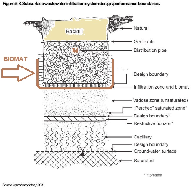
This sketch shows a cross section of a typical drainfield trench, and places below the trench the critical biomat as well as other septic field design areas and considerations. (Source :US EPA who in turn obtained the drawing from Ayres Associates)
This section discusses the design requirements for conventional septic absorption fields, also called leach fields, drain fields, drainfields, soakaway beds, seepage beds, or conventional soil absorption systems.
...
a. Site Requirements for conventional septic drainfields
(i) The minimum distances that absorption fields shall be separated from other facilities are shown in the sketch below.

See details and tables of septic component separation distances from various site features found
at CLEARANCE DISTANCES, SEPTIC SYSTEM
(ii) A minimum of four feet of usable soil shall exist above bedrock and groundwater with a minimum separation of two feet to the lowest part of any trench.
(iii) Absorption fields shall not be built under driveways, parts of buildings or under above-ground swimming pools or other areas subject to heavy loading. Surface waters shall be diverted from the vicinity of the system.
...
b. Design Criteria for conventional septic drainfields
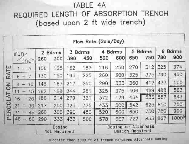
(i) The required length of absorption trench is determined from Table 4A based upon the percolation test results and confirmed by the soil evaluation. The maximum trench width for design purposes shall be 24 inches. Only 24 inches shall be allowed for absorption area calculations. W
here trenches exceed 24 inches in width, calculations of absorptive area shall be based on a width of 24 inches.
(ii) Adjacent trenches shall be separated by at least four feet of undisturbed soil. Individual trenches shall be constructed parallel to the ground contours with trench bottoms as near level as possible. They need not be perfectly straight but abrupt changes in direction shall be avoided.
Table 4A of Septic Drainfield Trench Lengths Determined by Soil Percolation Rate and Daily Wastewater Input Flow
P
|
Table 4A - Septic Wastewater Effluent Input Flow Rate (Gallons per Day) [1] |
||||||||||
| Minutes / Inch |
2 Bdrms |
3 Bdrms |
4 Bdrms |
5 Bdrms |
6 Bdrms |
||||||
| 260 gpd |
300 gpd |
390 gpd |
450 gpd |
520 gpd |
600 gpd |
650 gpd |
750 gpd |
780 gpd |
900 gpd |
||
Required number of feet of absorption trench, assuming a 2-ft wide conventional gravel trench |
|||||||||||
| 1 - 5 | 108 ft. | 125 ft. | 162 ft. | 187 ft. | 216 ft. | 250 ft. | 270 ft. | 312 ft. | 325 ft. | 374 ft. | |
| 6 - 7 | 130 | 150 | 195 | 225 | 260 | 300 | 325 | 375 | 390 | 450 | |
| 8 - 10 | 145 | 167 | 217 | 250 | 290 | 333 | 360 | 417 | 433 | 500 | |
| 11 - 15 | 162 | 188 | 244 | 281 | 325 | 375 | 406 | 469 | 488 | 563 | |
| 16 - 20 | 186 | 214 | 279 | 321 | 372 | 429 | 464 | 536 | 557 | 643 | |
| 21 - 30 | 217 | 250 | 325 | 375 | 433 | 500 | 542 | 625 | 650 | 750 | |
| 31 - 45 | 260 | 300 | 390 | 450 | 520 | 600 | 650 | 750 | 780 | 900 | |
| 46 - 60 | 290 | 333 | 433 | 500 | 578 | 667 | 722 | 833 | 867 | 1000[2] | |
| Dosing not required (but recommended) |
Dosing system or alternative design is required | ||||||||||
Notes to the Septic Drainfield Trench Length Table Above
[1] Original source: New York State NYS75-A.8 Table 4A [image file]
[2] Conditions that require more than 1000 feet of septic drainfield trench must have an alternative dosing system design.
An Alternate Table for Determining Septic Drainfield Size
The following is adapted from our engineer's article summarizing "How Big Should the Septic Leach Field Be" found at
HOW BIG SHOULD THE LEACH FIELD BE?
Determining the required size of a leach field is a bit more complicated. The first thing to consider is the nature of the soil in which the leach field is to be constructed. Because water has to be absorbed in the soil, we need to know how fast it can be absorbed.
This is called the percolation rate and is expressed as the time it takes for water in a test hole to decrease in level by one inch (minutes/inch).
We must also know the type of soil and whether seasonal changes in the natural level of groundwater will interfere with the satisfactory operation of the system. Seasonal groundwater must be more than four feet from the bottom of the leach field trenches.
Judgments regarding the soil conditions and percolation rates are best left to a professional. If the soil percolates very quickly, (less than one minute per inch) or very slowly (greater than 60 minutes per inch) it will not be possible to install a standard leach field in the existing soil.
We must now determine the amount of water that has to be absorbed each day. As with the septic tank sizing, there are also "rules of thumb" that can be used to find out how much water must be absorbed each day for each bedroom in the house (expressed as gallons per day per bedroom).
- For older houses
(built before 1979)
we must allow 150 gallons per day (gpd) per bedroom. - Homes with 3.5 gpf toilets:
For houses where the toilets are limited to no more than 3.5 gallons per flush and the faucets and showerheads are limited to 3 gallons per minute or less, we must allow 130 gpd per bedroom. - Homes with 1 gpf toilets:
For houses with water-saving toilets that use only one gallon per flush we allow 90 gpd per bedroom.
The required flow rate is found by multiplying the appropriate flow by the number of bedrooms (in this case, we do not have to count a garbage disposal as a bedroom).
Knowing the rate at which water can be absorbed by the soil (the percolation rate) and the flow rate (in gallons per day), we can use the following table to calculate how many square feet of absorption field is needed.
Readers will notice that this table is similar to but less detailed than our typical state or board of health table above at TABLE 4A.
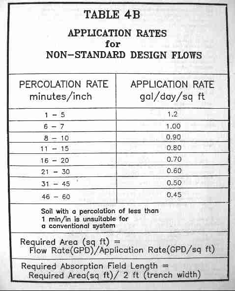
This table specifies the allowable wastewater application rate into the soil of a conventional septic system drainfield as a function of the soil percolation rate for percolation rates between 1 minute per inch to 60 minutes per inch.
Table 4B - Septic Drainfield Soil Application Rates for Non-Standard Wastewater Flow Quantities
This table specifies the allowable wastewater application rate into the soil of a conventional septic system drainfield as a function of the soil percolation rate for percolation rates between 1 minute per inch to 60 minutes per inch.
In other words, the table shows the allowable volume of wastewater in gallons that can be applied per day per square foot of septic field size.
Soils with a percolation rate of less than 1 minute per inch should not be used for a conventional septic drainfield.
Readers will note that this table considers only the dimensions of the bottom of the drainfield trench in considering the effective soil absorption area.
Typically a conventional drainfield trench is 2 ft. wide, so the effective absorption area is simply 2 ft. x field-length in ft.
Beware that in some jurisdictions, when calculating required drainfield trench lengths the authorities may consider the trench width to be a nominal one-foot wide regardless of its actual width.
Table 4B - Required Size Septic Leach Field for Non-Standard Flows |
|
| Absorption Percolation Minutes per Inch |
Allowable Application Rate - Gallons per Day per Square Foot |
| > 1 | Not Acceptable |
| 1 - 5 | 1.2 |
| 6 - 7 | 1.0 |
| 8 - 10 | 0.9 |
| 11 - 15 | 0.8 |
| 16 - 20 | 0.7 |
| 21 - 30 | 0.6 |
| 31 - 45 | 0.5 |
| 46 - 60 | 0.45 |
Notes to the table just above
Original source: New York State Septic Design Code TABLE 4B - APPLICATION RATES [Image File]
- Soil with a percolation rate of less than 1 minute /inch or more than 60 minutes/inch is unsuitable for a conventional septic system design: the wastewater will be absorbed into surrounding soil too rapidly to permit adequate treatment.
- Required Septic Absorption Field Area = Flow Rate (GPD) / Application Rate (GPD / Sq. Ft.)
- Required Septic Absorption Field Length = Required Area (Sq. Ft.) / 2 ft (assumed trench width)
- Note that this table considers only the dimensions of the bottom of the drainfield trench in considering the effective soil absorption area. Typically a conventional drainfield trench is 2 ft. wide, so the effective absorption area is simply 2 ft. x field-length in ft.
- Note that some jurisdictions may set a maximum length of 100 ft. (or another figure) for absorption field trench length.
- Beware that in some jurisdictions, when calculating required drainfield trench lengths the authorities may consider the trench width to be a nominal one-foot wide regardless of its actual width.
...
c. Materials Used for conventional septic drainfields
(i) Perforated distributor pipe shall be used in the trenches.
(ii) Solid (non-perforated) pipe shall be used between the distribution box and the trenches.
(iii) Perforated pipe shall be made of rigid or corrugated plastic and be labeled as fully meeting ASTM standards for use in septic
systems.
(iv) Corrugated plastic pipe delivered in coils is not to be used unless provision is made to prevent the recoiling or movement of the
pipe after installation.
(v) Aggregate shall mean washed gravel or crushed stone 3/4 - 1 1/2 inches in diameter. Larger diameter material or finer substances and run-of-bank gravel are unacceptable.
(vi) The aggregate shall be covered with a material that prevents soil from entering the aggregate after backfilling, yet must permit air and moisture to pass through.
(vii) The preferred material for covering the aggregate is a permeable geotextile. Untreated building paper or a four inch layer of hay or straw is acceptable. Polyethylene and treated building paper are relatively impervious and shall not be used.
...
d. Construction of conventional septic drainfields
(i) Septic drain field trench locations and depths
should be marked by stakes before the trenches are excavated. The natural surface shall not be significantly
disturbed.
If
the site is re-graded or similarly disturbed, the soil shall be allowed to stabilize and new percolation tests conducted.
(ii) Septic drainfield trench depth shall be as shallow as possible,
but not less than 18 inches. At least six inches of aggregate is placed below the
distribution line and two inches above the line. The earth cover over the aggregate should not exceed 12 inches in order to enhance natural
aeration and nitrogen uptake by plant life.
(iii) Septic drainfield or soakaway trenches shall be excavated
to design depth with bottoms practically level.
(iv) Heavy equipment
shall be kept away from the field because the weight may permanently alter
soil characteristics due to compaction, cause trench cave-ins, and/or mis-align and break pipe.
(v) Septic drainfield or soakbed trench bottoms
are to be raked and immediately covered with at least six inches of aggregate.
(vi) Septic drainfield / leachfield trench walls:
Any smeared surfaces on the trench walls are to be raked.
(vii) Septic drainfield effluent distribution lines
are carefully placed on the aggregate and covered with
aggregate to a depth of at least two inches over the top of the pipe. Additional aggregate may be required to bring the top of the aggregate
to within six to 12 inches of the surface.
(viii) In gravity distribution septic systems, the pipe shall be carefully sloped
at between 1/16 inch and 1/32 inch per foot. Grades shall be determined
by an engineer's level, transit or carpenter's level.
(ix) Septic drainfield / soakbed trench cover:
After the upper aggregate is placed, the geotextile, untreated building paper, hay or straw is to be immediately installed and the
trench backfilled with native soil.
If the drainfield trenches cannot be immediately backfilled, they should be temporarily covered with an
impervious material such as treated building paper to prevent sidewall collapse and siltation into the aggregate.
(x) Septic drainfield / soakaway trench backfill:
The earth backfill is to be mounded slightly above the original ground level to allow for settling and after settlement the entire area
should be graded without the use of heavy equipment and seeded with grass.
[See our warnings at CONSTRUCTION OF SHALLOW SEPTIC SYSTEM ABSORPTION TRENCHES]
...
Continue reading at SEPTIC DRAINFIELD SHAPE or select a topic from the closely-related articles below, or see the complete ARTICLE INDEX.
Or see SEPTIC DRAINFIELD SIZE FAQs - reader questions & answers.
Or see these
Recommended Articles
- NEW YORK STATE 75-A.8 SUBSURFACE TREATMENT of EFFLUENT
- SEPTIC DRAINFIELD INSPECTION & TEST - home
- SEPTIC DRAWINGS
- SEPTIC SOIL & PERC TESTS
- SEPTIC SYSTEM DESIGN ALTERNATIVES - home
- SEPTIC SYSTEM DESIGN BASICS
- SEPTIC TANKS - home
- U.K. OFF-GRID SEPTIC REGULATIONS & SEWAGE SYSTEMS
- U.S. SEPTIC AUTHORITIES & DESIGN SPECIFICATIONS - Septic codes & regulations for each US State or Territory
Suggested citation for this web page
SEPTIC DRAINFIELD DESIGN - CONVENTIONAL at InspectApedia.com - online encyclopedia of building & environmental inspection, testing, diagnosis, repair, & problem prevention advice.
Or see this
INDEX to RELATED ARTICLES: ARTICLE INDEX to SEPTIC DRAINFIELDS & DBOXES
Or use the SEARCH BOX found below to Ask a Question or Search InspectApedia
Ask a Question or Search InspectApedia
Share this article:Questions & answers or comments about septic drainfield or soakaway bed size or capacity requirements & design.
Try the search box just below, or if you prefer, post a question or comment in the Comments box below and we will respond promptly.
Search the InspectApedia website
Note: appearance of your Comment below may be delayed: if your comment contains an image, photograph, web link, or text that looks to the software as if it might be a web link, your posting will appear after it has been approved by a moderator. Apologies for the delay.
Only one image can be added per comment but you can post as many comments, and therefore images, as you like.
You will not receive a notification when a response to your question has been posted.
Please bookmark this page to make it easy for you to check back for our response.
IF above you see "Comment Form is loading comments..." then COMMENT BOX - countable.ca / bawkbox.com IS NOT WORKING.
In any case you are welcome to send an email directly to us at InspectApedia.com at editor@inspectApedia.com
We'll reply to you directly. Please help us help you by noting, in your email, the URL of the InspectApedia page where you wanted to comment.
Citations & References
In addition to any citations in the article above, a full list is available on request.
- ASSE, PLUMBING DICTIONARY [PDF] 6th Ed., (2007) American Society of Sanitary Engineering, 18927 Hickory Creek Drive, Suite 220, Mokena IL 60448 USA Tel: 708-995-3019, Website: www.asse-plumbing.org
- NYS DOH, RESIDENTIAL ONSITE WASTEWATER TREATMENT SYSTEMS HANDBOOK [PDF] (2012) - original source: http://www.ongov.net/health/env/documents/DesignHandbook10_24_2
- WA DOH, BASIC PRINCIPLES of ONSITE SEWAGE [PDF] (1992) Washington State Department of Health, Office of Water, Washington D.C. USA
Also including as
APPENDIX A: WHY DO COARSE SOILS HAVE LARGER PORE SIZE & LESS SURFACE AREA? & WHY DO FINER SOILS HAVE SMALLER PORE SIZE & MORE SURFACE AREA
and
Cogger, Craig G., APPENDIX B: SEPTIC SYSTEM WASTE TREATMENT in SOIL, (1987) Washington State University Cooperatie Extension, EB1475, - [1] US EPA ONSITE WASTEWATER TREATMENT SYSTEMS MANUAL [online copy, free] Top Reference: US EPA's Design Manual for Onsite Wastewater Treatment and Disposal, 1980, available from the US EPA, the US GPO Superintendent of Documents (Pueblo CO), and from the National Small Flows Clearinghouse.
Original source http://www.epa.gov/ORD/NRMRL/Pubs/625R00008/625R00008.htm Onsite wastewater treatment and disposal systems, Richard J Otis, published by the US EPA. Although it's more than 20 years old, this book remains a useful reference for septic system designers.
U.S. Environmental Protection Agency, Office of Water Program Operations; Office of Research and Development, Municipal Environmental Research Laboratory; (1980) - [2] "International Private Sewage Disposal Code," 1995, BOCA-708-799-2300, ICBO-310-699-0541, SBCCI 205-591-1853, available from those code associations.
- [3] "Manual of Policy, Procedures, and Guidelines for Onsite Sewage Systems," Ontario Reg. 374/81, Part VII of the Environmental Protection Act (Canada), ISBN 0-7743-7303-2, Ministry of the Environment,135 St. Clair Ave. West, Toronto Ontario M4V 1P5 Canada $24. CDN.
- [4] Manual of Septic Tank Practice, US Public Health Service's 1959.
- [5] "Installers Manual for Conventional Onsite Domestic Wastewater Treatment and Disposal Systems", Department of Environmental Conservation, Division of Environmental Health Drinking Water and Domestic Wastewater Program, Alaska Department of Environmental Conservation, 1 Aug 2000, Anchorage Offices, 555 Coredova, Anchorage AK 99501, Tel: 907-269-7500. retrieved 17 July 2012, original source: http://dec.alaska.gov/water/wwdp/onsite/pdf/Certified_Installer%27s_Manual.pdf [Copy on file as Alaska_Certified_Installer's_Manual.pdf].
Notice: [Quoting]
This document contains information regarding the installation of onsite sewer systems for single-family and duplex residences.
It must be used by Certified Installers and homeowners who are subject to 18 AAC 72. Additional requirements are included in 18 AAC 72. If there is a conflict between the provisions of this manual and 18 AAC 72, 18 AAC 80, or other state regulations, the regulations language controls. AEDC offices.
The regulations cited above for Alaskans can be found at https://dec.alaska.gov/commish/newsroom/23-15-updated-onsite-wastewater-regulations/ - [7] Percolation Testing Manual, CNMI Division of Environmental Quality, PO Box 501304, Saipan, MP 96950
- [8] Test Pit Preparation for Onsite Sewage Evaluations, State of Oregon Department of Environmental Quality, Portland OR, 800 452-4011. PDF document. We recommend this excellent document that offers detail about soil perc tests, deep hole tests, safety, and septic design.
- [9] Wells and Septic System, Alth, Max and Charlet, Rev. by S. Blackwell Duncan, $ 18.95; Tab Books 1992.
- [17] Thanks to reader Michael Roth for technical link editing 6/29/09.
- [19] Septic Tank/Soil-Absorption Systems: How to Operate & Maintain [ copy on file as /septic/Septic_Operation_USDA.pdf ] - , Equipment Tips, U.S. Department of Agriculture, 8271 1302, 7100 Engineering, 2300 Recreation, September 1982, web search 08/28/2010, original source: http://www.fs.fed.us/t-d/pubs/pdfimage/82711302.pdf.
- The NSFC Products List has an excellent list of design manuals/modules National Small Flows Clearinghouse (NSFC) now (2019/12/13) hosted at http://www.nesc.wvu.edu/ Tel: 304-293-4191 e-mail info@mail.nesc.wvu.edu. telephone 800-624-8301
- In addition to citations & references found in this article, see the research citations given at the end of the related articles found at our suggested
CONTINUE READING or RECOMMENDED ARTICLES.
- Carson, Dunlop & Associates Ltd., 120 Carlton Street Suite 407, Toronto ON M5A 4K2. Tel: (416) 964-9415 1-800-268-7070 Email: info@carsondunlop.com. Alan Carson is a past president of ASHI, the American Society of Home Inspectors.
Thanks to Alan Carson and Bob Dunlop, for permission for InspectAPedia to use text excerpts from The HOME REFERENCE BOOK - the Encyclopedia of Homes and to use illustrations from The ILLUSTRATED HOME .
Carson Dunlop Associates provides extensive home inspection education and report writing material. In gratitude we provide links to tsome Carson Dunlop Associates products and services.
 |
HOME | ABOUT | ASK a QUESTION | CONTACT | CONTENT USE POLICY | DESCRIPTION | POLICIES | PRIVACY | |
| © 2026 - 1985 Publisher InspectApedia.com - Daniel Friedman | |||||||||