 Types of Mixing Valves & Anti Scald Valves
6 approaches to water temperature control to avoid scalding burns

- POST a QUESTION or COMMENT about different types of anti scald devices and mixing valves on hot water systems.
Six types of anti-scald protection or hot water temperature control for building hot water supply systems.
Safety standards for all eight types of water temperature controls used in buildings.
Where will you find or install water temperature controls on building hot water systems?
InspectAPedia tolerates no conflicts of interest. We have no relationship with advertisers, products, or services discussed at this website.
- Daniel Friedman, Publisher/Editor/Author - See WHO ARE WE?
Types of Anti-Scald Water Temperature Controls for Building Plumbing Systems
 Here we describe all of the types of devices installed at water heaters or at the point of use of hot water to regulate water temperature and to avoid scalding burns.
We separate these controls by where they are installed (point of source or point of use), and we further separate them by the method used to control water temperature.
The names and claimed features of anti-scald water temperature controls used on plumbing systems can be confusing even to plumbing and heating technicians and certainly to building owners and to many home inspectors.
In our OPINION this may be in part due to fear of lawsuit. Some manufacturers don't use the word "scald" anywhere in their product literature, others don't even make clear reference to "temperature" even when the purpose of the device is to regulate water temperature or to prevent surges of hot or cold water.
Heck, some don't even want to use the word "control" since in fact, at the end of the day, the temperature of water coming out of a shower head or tub spout can vary for a lot of reasons.
A review of the temperature control devices currently sold for building plumbing systems shows several different approaches to temperature controls and may also claim different purposes of those controls, as we outline here.
Watch out: At ANTI SCALD VALVES & TEMPERATURE CONTROL / MIXING VALVES we provide an extensive list of brands and models of hot water flow and temperature control devices
. When choosing and installing any of those devices it is essential that the installer understand the hot water control and anti scald purposes, performance, and properties of the device and its setting requirements. Otherwise the hot water supply system may be unsafe and may risk serious scalding burns of a user.
Because some of those product descriptions are not always completely clear, installers should review the ASSE/ASME standards discussed here as well.
Article Contents
- WHERE are ANTI-SCALD or TEMPERATURE CONTROLS FOUND - point of source, point of use, other
- SAFETY STANDARDS for ALL 8 TYPES of WATER TEMPERATURE CONTROLS - used in buildings
- SIX COMMON TYPES of WATER TEMPERATURE & FLOW CONTROLS in BUILDINGS
- TEMPERATURE CONTROL ON the WATER HEATER - POS or point-of-source control
- THERMOSTATICALLY CONTROLLED MIXING VALVE AT the WATER HEATER - POS or point-of-source control
- MANUAL MIXING or TEMPERING VALVE AT the WATER HEATER - POS or point-of-source control (or possibly elsewhere)
- MECHANICAL STOP TEMPERATURE LIMIT at FIXTURE - POU or point-of-use control - temperature controls installed at a shower, sink, or bath tub.
- PRESSURE COMPENSATING CONTROL at FIXTURE - POU or point-of-use control - also installed at a shower, sink, or bath tub.
- THERMOSTATIC HOT WATER TEMPERATURE CONTROL at POINT OF USE - or POS - point of source for some devices - also installed at a shower, sink, or bath tub.
- ANTI SCALD THERMOSTAT & MIXING VALVE STANDARDS & RESEARCH
For a complete inventory of all of the methods used to control water temperature in buildings, please
see WATER HEATER TEMPERATURE ADJUSTMENT CONTROLS - home
...
Locations of Anti Scald or Temperature Control Valves
- POS: Point of source:
these controls are installed at or close to the water heater or at the heating boiler that uses a tankless coil as a tempering or mixing valve using any of several methods to control outgoing water temperature to the entire building, detailed below.
POS hot water temperature controls listed here are most-often completely independent of the actual thermostatic control found on electric, gas, oil, or solar water heaters themselves.
Typically these POS temperature controls allow the water heater to be maintained at a higher temperature while mixing sufficient cold water with the outgoing hot water as to control its temperature within a desired range.
This approach permits two central advantages of high water temperatures (above scalding) in the water heater itself:
- prevention of Legionella and other bacterial contamination of the hot water heater and its supply
- provision of a greater total quantity of hot water (at temperatures below-scalding) to the building's occupants. - POU: Point of use:
these hot water temperature controls are installed at or close to the point of use or individual plumbing fixture as we detail below.
A POU device may be integrated with the actual plumbing fixture control such as a single-handle shower or tub control, or it may be installed at the plumbing fixture, but just ahead of the fixture's user-control. - Downstream devices that are neither POS nor POU:
Occasionally, elsewhere in the building, such as for an individual building floor or an entire apartment in a multi-occupancy building
...
Safety Standards for 8 Types of Mixing Valves or Tempering Valves or Pressure Controls
Excerpting from ASSE, GUIDELINES for TEMPERATURE CONTROL DEVICES in DOMESTIC HOT WATER SYSTEMS [PDF] cited in more detail below we describe three hot water flow / temperature control locations, each of which has different standards, requirements, and properties.
- ASSE 1016: Temperature controls at the shower or tub/shower - these are POU or point-of-use devices and in the U.S. must comply with ASSE 1016 / ASME A112.1016
These are automatic temperature compensating valves intended for wall-mounted shower or tub/shower controls at which the user or user's attendant can access and control the final hot water temperature at the fixture.
Three ASSE 1016 tub/shower control types are available:
ASSE 1016 Water Temperature Controls
User or user's attendant can access and control the final hot water temperature at the fixture
Type Hot/Cold
Supply
PressureHot Temp.
IncreaseTemp
Variation
Within
SecondsMinimum
Flow
(gpm)Cold
Water
FailureT: Thermostatic +/- 20% 25°F, 5°F/min +/- 3.6°F / 2.0°C
5 seconds2.5 gpm <= 0.5 gpm P: Pressure +/- 50% None +/- 3.6°F / 2.0°C
1 second2.5 gpm <= 0.5 gpm T/P: Combined +/- 50% 25°F, 5°F/min +/- 3.6°F / 2.0°C
1 second2.5 gpm <= 0.5 gpm Notes to the table above
Hot Temp. Increase: this describes the automatic temperature compensation limits, maximum variation & permitted rate of variation.
User can adjust temperature & water flow rates or "volume"
There is no additional water temperature control or mixing device downstream from an ASSE 1016 control.
The temperature control to within +/- 3.6 °F is a 2005 standard.
Adapted from Watts Water Technologies PPT cited in detail below on this page. - ASSE 1017: Temperature controls at the hot water source - these are POS or point-of-source thermostatic-type devices and in the U.S. must comply with ASSE 1017
Used at sinks, lavatories, bidets, public hand washing facilities, an additional water temperature control device may also be placed downstream from an ASSE 1017 control. Therefore the final temperature at the fixture is under user control.
At bathtub & whirlpool bath (spa) plumbing valves in compliance with IPC Section 424.5 - Bathtub & Whirlpool bathtub valves requiring water temperature to be limited to a maximum of 120°F (49°C)
At bidets in compliance with IPC Section 408.3 - Bidet Water Temperature, limited to a maximum of 110°F (43°C)
At public hand-washing facilities in compliance with International Plumbing Code IPC Section 416.5, Tempered water for public hand washing facilities.
ASSE 1070 Water Temperature Controls
User or user's attendant can access and control the final hot water temperature at the fixtureStandard Hot/Cold
Supply
PressureHot Temp.
IncreaseTemp
Variation
Minimum
Flow
(gpm)Cold
Water
FailureTemp
LimitsASSE1070 +/- 20% 25°F, 5°F/min +/- 7°F /14°C Manufacturer's
stated gpm<= 0.2 gpm
or
20% of min. flow
whichever is
greaterBidet: 110°F (43°C)
Tub: 120°F (49°C)
An ASSE 1070 device reduces the risk of scalding but may not prevent thermal shock when other uses of hot or cold water nearby affect the flow and temperature at a given fixture.
The device must prevent uncontrolled cross-flow between hot and cold supply lines.
These devices control the temperature of hot water at a fixture control by mixing in cold-water as required to meet a specific temperature limit: - ASSE 1062: Temperature controls at individual supply fittings - TAFR Valves - these are POU devices and in the U.S. must comply with ASSE 1062
- ASSE 1066: In-Line water pressure balancing devices at individual fixtures - these are POU devices and in the U.S. must comply with ASSE 1066
- ASSE 1069: Single supply pipe tempered water temperature - installed at or between a hot water source and final-use fixture, typically supplying multiple fixtures, these devices must comply with ASSE 1069
These are automatic, temperature-controlled mixing valves using a preset temperature control, used at gang shower, sitz baths, or similar devices serving end-use plumbing controls that must comply with the 2006 IPC Section 424.4 - Multiple (gang) showers.
Tempered water is supplied to the plumbing fixtures through a single pipe at a fixed or preset supply temperature. Users can not control the water temperature.
ASSE 1069 Water Temperature Controls
User can NOT control the final hot water temperature at the fixture
Standard Hot/Cold
Supply
PressureHot Temp.
IncreaseTemp
Variation
Minimum
Flow
(gpm)Cold
Water
FailureTemp.
LimitASSE1069 +/- 20% 25°F, 5°F/min +/- 3.6°F /16°C
within
5 seconds2.5 gpm
or
Manufacturer's
stated gpm<= 0.5 gpm for
pipe < 3/4"
<= 1.0 gpm for
pipe => 1"120°F (49°C)
There are no downstream temperature controls.
Maximum temperature setting: 120°F (49°C) - ASSE 1070: Temperature controls at fixture / devices, downstream mixing permitted - these are POU devices for sinks, tubs, bidets that reduce scalding risk and in the U.S. must comply with ASSE 1070.
- ASSE 1071: Emergency Plumbing Equipment temperature controls. These are POU devices providing "tepid" water for emergency use such as an emergency eye wash station, and in the U.S. must comply with ASSE 1071
- Multi-ASSE Devices may provide or combine multiple functions may be listed for both POS & POU uses though often such devices must be installed to provide only a single function at a time, requiring additional devices as well..
Some hot water temperature or flow or "pressure" controls are listed to multiple standards, ( ASSE 1017, ASSE 1069, ASSE 1070).
Example: Cash Acme HEATGUARD 110-D SERIES TEMPERATURE-ACTUATED MIXING VALVE specifications say the valve meets ASSE 1017, 1069, 1070 as well as CA B 125.3.
ASSE warns that these devices should NOT be installed to simultaneously control both one individual fixture's hot water temperature AND serving as a control for the entire hot water system.
In addition, when a multi-listed device is installed as a POS instrument (at the hot water source), ASSE says it should be considered as an ASSE 1017 device (item 2 in our list above).
That means that an additional POU device (at the fixture) is required and must meet the standards of one of the POU type devices in our list above (items 1,3,4,5,6, or 7)
Watch out: as you'll read in manufacturer-provided product descriptions of various hot water flow and temperature control devices, the intended location - POS POU - is usually stated but just how the device works is not always explained and may be opaque to the buyer, installer, or user.
Without understanding the operation of the hot water control the installer or user may also not understand its limitations nor what protection it can or can not provide.
1. Temperature Controls at Shower or Tub/Shower Fixtures: ASSE 1016 / ASME A112.1016
Shower valves shall be automatic temperature and/or pressure compensating valves intended to be installed at an individual shower or tub/shower combination.
- These valves must comply with ASSE 1016-2011 / ASME A112.1016-2011/CSA B125.16-11, Performance Requirements for Automatic Compensating Valves for Individual Showers and Tub/Shower Combinations.
- The user has access to flow and/or final temperature controls. No further mixing occurs downstream of the device.
- These devices are intended to control the water temperature to wall- or ceiling-mounted:
a. Hand-held showers;
b. Shower heads;
c. Body sprays, either in individual shower or tub/shower combination fittings;
d. Tub spouts, when part of tub/shower combination fittings. - There are three different types shower valves that meet this standard:
a. Pressure balancing
b. Thermostatic (mechanical and electronic)
c. Combination pressure balancing and thermostatic - The shower head flow rate must not be less than the manufacturer’s published minimum flow rate for the valve (device).\
- The temperature limit stop must be set at the time of installation, and may need to be periodically adjusted for variations in water temperatures.
- These devices provide both scald and thermal shock protection.
2. Temperature Controls Installed At or Near the Hot Water Source: ASSE 1017
Temperature actuated mixing valves for hot water distribution systems are used for controlling in-line water temperatures in domestic hot water systems.
- These valves must comply with ASSE 1017-2009, Performance Requirements for Temperature Actuated Mixing Valves for Hot Water Distribution Systems.
- When used, these devices shall be installed at or near the outlet of the hot water source ONLY.
- These valves are designed to provide a relatively uniform water temperature to the hot water distribution system.
- As a side benefit, these valves allow the water to be stored at a higher temperature, extending the amount of hot water available, and also reducing the chance of Legionella (ASHRAE Guideline 12).
- These valves are NOT intended for point of use applications.
- Valves must be sized to match the flow requirements of the system (as shown in the ASSE table below)
Water |
Allowable Temperature Fluctuation |
| GPM | ° F |
| 0 - 5 | ±3° F |
| 5 - 40 | ±5° F |
| Over 40 | ±7° F |
Notes to the table above
Excerpted from ASSE, GUIDELINES for TEMPERATURE CONTROL DEVICES in DOMESTIC HOT WATER SYSTEMS [PDF] cited in more detail below:
- Further mixing downstream is allowed to provide final temperature control to protect against scalding.
- These devices used alone do not provide thermal shock protection or adequate scald protection.
- Installation note: to prohibit the cross-flow of hot or cold water through the valve, supplementary check valves are recommended for devices that do not include integral check valves.
3. Temperature controls at individual supply fittings - TAFR Anti-Scald Valves: ASSE 1062
TAFR valves are another type of POU or point-of-use temperature control intended to reduce the risk of scalding burns.
A TAFR valve is an acronym for Temperature Actuated Flow Reduction. TAFR valves will reduce hot water flow to a trickle or less if water temperature at the fixture exceeds a preset temperature. The preset temperature itself must be 120° F (48.9° C) or less.
- Temperature actuated, flow reduction (TAFR) valves, when used, shall be installed on the discharge outlet of the fixture fitting or integrated into fixture fittings.
- These valves must comply with ASSE 1062-2006, Performance Requirements for Temperature Actuated Flow Reduction (TAFR) Valves for Individual Fixture Fittings.
- Intended for use in-line with, or integrated into, individual plumbing supply fittings such as shower heads, bathtubs, whirlpool bathtubs, utility sink faucets, kitchen sinks, and lavatory faucets.
- Designed to automatically reduce flow to a trickle within five seconds of outlet temperatures greater than a preset actuation temperature not to exceed 120° F (48.9° C).
- During the five (5) second response period, the bather may be exposed to temperatures in excess of the set point of the device.
- After actuation, the device shall reset and open automatically at a predetermined lower temperature, or with the use of a manual reset mechanism.
- These devices can be used on existing fixtures to provide scald protection – typically, where no other form of scald protection is provided.
- TAFR valves are not intended to be installed in place of devices complying with ASSE 1016, ASSE 1017, ASSE 1066, ASSE 1069, or ASSE 1070.
- These devices provide scald protection ONLY, and DO NOT provide thermal shock protection.
Watch out: ASSE warns that:
These valves automatically reduce discharge flow to a trickle if water temperature exceeds a preset limit. This trickle can be as much as 0.25 GPM (0.95 L/m). When this device is installed on a bathtub spout and the outlet temperature exceeds the preset limit, and if the bathtub drain is closed, the bathtub could fill with extremely hot water from this allowable trickle.
Watch out: ASSE also warns that
Some ultra-low-flow shower heads may still have a full spray pattern when the flow through this TAFR device is reduced.
The Apollo DUAL PURPOSE THERMOSTATIC MIXING VALVE appears to us to be a TAFR device and is described later on this page.
4. In-Line Pressure Balancing Devices at Individual Fixtures: ASSE 1066
- Automatic pressure balancing in-line valves are used to equalize incoming hot and cold water line pressures. This minimizes mixed water temperature variations due to pressure fluctuations when used in conjunction with a mixing valve or two handle valve set.
- These valves must comply with ASSE 1066-1997, Performance Requirements for Individual Pressure Balancing In-Line Valves for Individual Fixture Fittings.
- They are not designed to limit the maximum outlet temperature at the point-of-use.
- These devices provide thermal shock protection for pressure disturbances ONLY, and DO NOT provide scald protection if the incoming hot or cold water temperature changes.
5. Tempered Water Through a Single Supply Pipe: ASSE 1069
- Automatic temperature control mixing valves shall be installed and set to supply only tempered water to the end user, and automatically compensate for pressure and/or temperature variations in water distribution systems.
- These valves must comply with ASSE 1069-2005, Performance Requirements for Automatic Temperature Control Mixing Valves.
- These devices have the capability to significantly reduce the outlet flow in the event of a cold water distribution system failure.
- The device is equipped with an adjustable means to limit the setting of the device towards the hot position. The temperature limit stop must be set at the time of installation, and may be adjusted by the building owner or representative.
- The device is designed to be the final temperature control.
- Intended to control the water temperature to individual or multiple fixtures.
- NOT intended for individual showers or tub/showers.
- Intended to be installed where the end user does NOT have access to the temperature adjustment means.
- Designed to supply only tempered water to the end user.
- No further mixing downstream of the device.
- Typically installed for gang (multiple) showers and sitz baths.
- These devices provide scald protection and thermal shock protection.
6. Temperature Control POU Devices with Downstream Mixing Permitted: ASSE 1070
- Water temperature limiting devices are intended to limit the hot or tempered water temperature supplied to fittings for fixtures such as sinks, lavatories, bidets, or bathtubs to reduce the risk of scalding.
- These devices must comply with ASSE 1070-2015/ASME A112.1070-2015/CSA B125.70-15, Performance Requirements for Water Temperature Limiting Devices.
- These devices are intended to supply tempered water to plumbing fixture fittings, or be integral with plumbing fixture fittings supplying tempered water.
- These devices shall have:
a. Fixed (non-adjustable) temperature setting; or
b. Temperature setting that can be:
i. Adjusted and locked in position; or
ii. Adjusted with the use of a tool to protect against adjustment by the user. - Further mixing downstream is allowed.
- These devices have an integral water temperature limiting capability. The user control allows the outlet temperature to be adjusted up to a maximum temperature of 120° F (49° C).
- These devices provide scald protection ONLY, and DO NOT provide thermal shock protection
7. Emergency Plumbing Equipment temperature controls: ASSE 1071
- Temperature actuated mixing valves are intended to be used as a component that can provide tepid water for emergency eye wash, eye wash/shower, drench showers, and combination units that comply with the requirements of ANSI Z358.1.
- These valves must comply with ASSE 1071-2012, Performance Requirements for Temperature
Actuated Mixing Valves for Plumbed Emergency Equipment.
- These valves, by themselves, do not meet the requirements of ANSI Z358.1.
- These valves consist of a hot water inlet, a cold water inlet, a mixed water outlet, a temperature
controlling element, and a means for adjusting the mixed water outlet temperature while in service.
- These valves also have a means to limit the maximum outlet temperature under normal operating conditions.
- Provisions shall be made so that the temperature cannot be inadvertently adjusted.
- These valves shall include a means of preventing cross-flow
- Ideally, these devices are intended to be installed as close as possible to the plumbed emergency equipment.
- These valves provide scald protection ONLY, and DO NOT provide thermal shock protection.
- These valves provide cold water bypass flow in the event of a hot water failure.
...
6 Types of water temperature/flow Controls Common in Buildings
Here, without a neat mapping into the various ASSE water temperature and flow controls listed above, taking a more-broad approach to water temperature controls found in buildings, we describe different approaches to avoiding scalding water temperatures at a plumbing fixture and we describe some of the limitations of each of these.
Watch out: while all of these devices affect the temperature and/or flow of hot water, some of them can not provide scald protection.
- TEMPERATURE CONTROL ON the WATER HEATER - POS or point-of-source control
- THERMOSTATICALLY CONTROLLED MIXING VALVE AT the WATER HEATER - POS or point-of-source control
- MANUAL MIXING or TEMPERING VALVE AT the WATER HEATER - POS or point-of-source control (or possibly elsewhere)
- MECHANICAL STOP TEMPERATURE LIMIT at FIXTURE - POU or point-of-use control - temperature controls installed at a shower, sink, or bath tub.
- PRESSURE COMPENSATING CONTROL at FIXTURE - POU or point-of-use control - also installed at a shower, sink, or bath tub.
- THERMOSTATIC HOT WATER TEMPERATURE CONTROL at POINT OF USE - or POS - point of source for some devices - also installed at a shower, sink, or bath tub.
Note: other hot water temperature controls across the complete range of types of water heating systems are detailed
...
Water heater temperature controls on the water heater itself
The first and most basic hot water temperature control is usually found right at the water heating device.
The appearance, location, and operation of temperature control at a water heater or calorifier or geyser will vary depending on the heater type and its fuel.
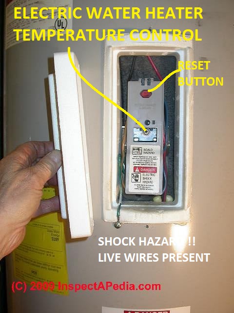
Shown below is one of the simplest controls, but one that's not visually obvious as it's behind the access panel on an electric water heater or geyser.
And below for contrast is the easily found and adjusted temperature control on a gas fueled water heater.
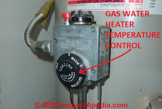
See details about the on-device or built-in temperature control found at each individual type of water heater
...
Thermostatically Controlled Mixing Valve for Water Temperature Control - POS or at the heater
Point of source (at the water heater) temperature control has been provided by automatic thermostatic mixing valves for at least the last 50 years, as we illustrate here.
Temperature is regulated by a thermostatic sensing device that automatically mixes cold water in with outgoing hot water to attempt to keep the output at a desired temperature.
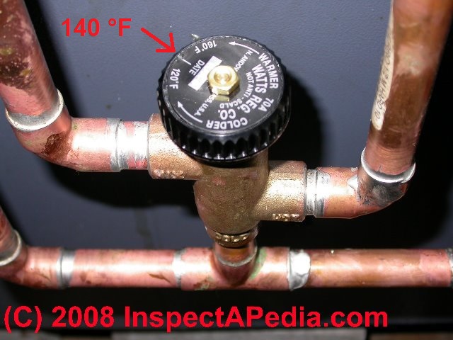
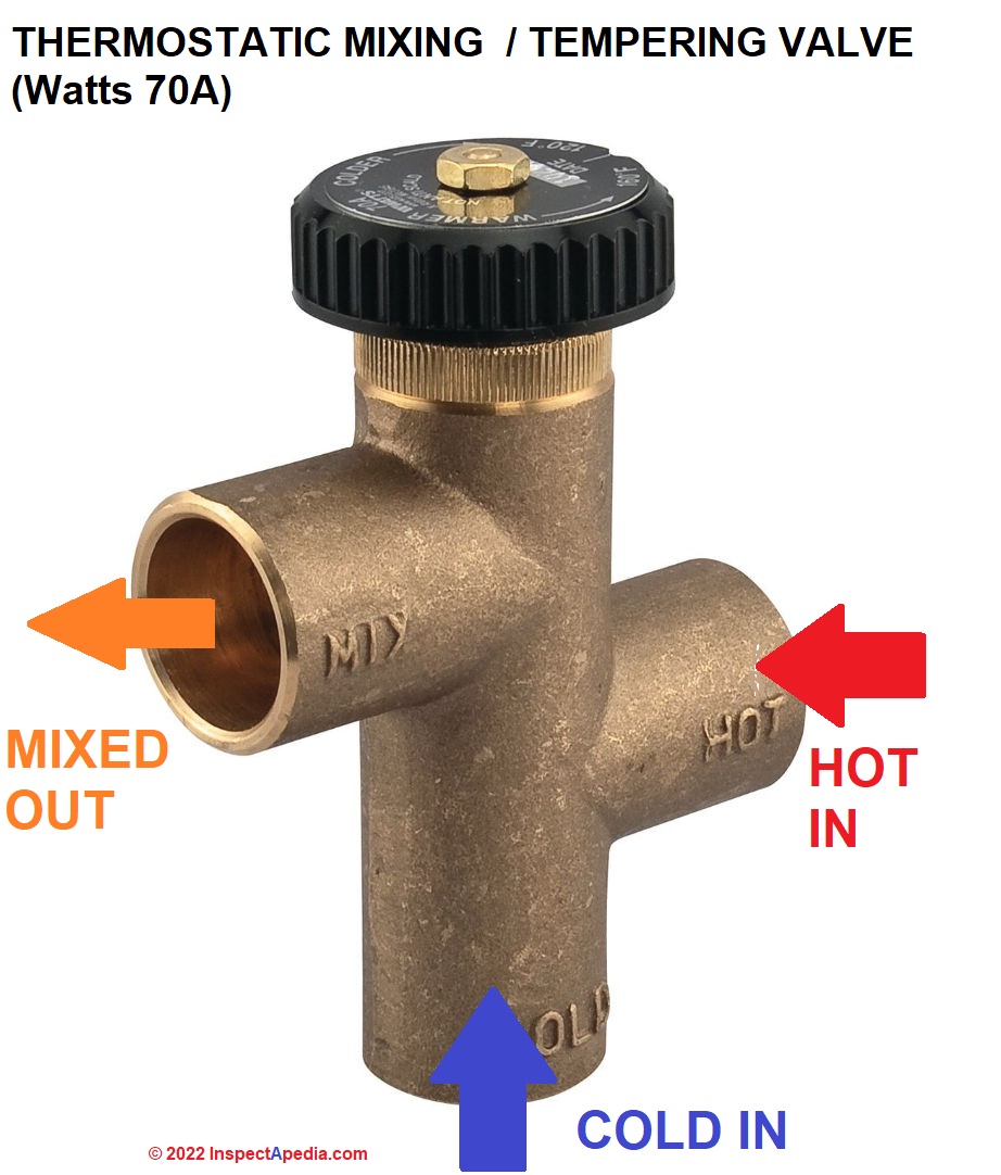
The mixing valve may be installed right at the hot water source such as at a tankless coil or water heater. An example of such a device is the traditional mixing valve found at tankless coils used to produce hot water from a heating boiler, shown above, using the Watts 70A as an example.
Watch out: the installation instructions for current Watts hot water temperature control valves, like the one shown here, often state that this valve is not to be used as an anti-scald device and warn that water pressure changes or water supply temperature changes can result in severe bodily injury (i.e., scalding or chilling) and/or death may result depending on system water pressure changes and/or water temperature changes.
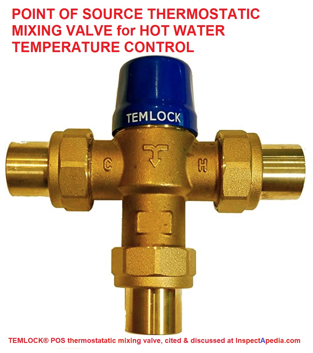
Another example of point-of-source thermostatic temperature control for hot water supply is the Temlock mixing valve shown below.
More about thermostatic mixing valves is
at ANTI SCALD VALVE at TANKLESS COIL
A temperature-sensing thermostatic mixing valve or anti-scald device can be installed at or near the water heating device so that even if the water heater is set to a high temperature, the building occupants won't be scalded when hot water is run at a plumbing fixture.
...
Manual Mixing Valve or Tempering Valve at the Water Heater
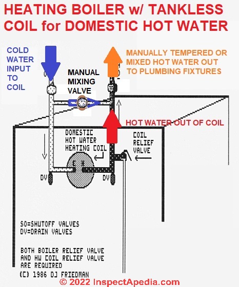
A manual mixing valve, such as those often installed at older tankless coil hot water systems, uses a simple gate valve that is manually adjusted by the homeowner. In our sketch, a manual mixing valve or tempering valve is placed between the incoming cold water line and the outgoing hot water line.
The building occupants can regulate the temperature of domestic hot water leaving this system by opening or closing the manual mixing valve.
At a minimum, the homeowner may have to adjust this valve seasonally, depending on whether or not the building is also being heated by the same boiler, as during the heating season the boiler will be kept hotter than during the rest of the year, making the outgoing hot water too hot.
Traditionally, the homeowner would need to close down the mixing valve in winter when incoming cold water was very cold, and then open it more widely in summer when incoming water was less cold.
Forgetting to make this twice-a-year adjustment to the manual mixing valve at the tankless coil could lead to a scalding burn in the shower in summer or water that was not hot enough in winter.

Details are
at MANUAL ANTI-SCALD TEMPERING VALVES
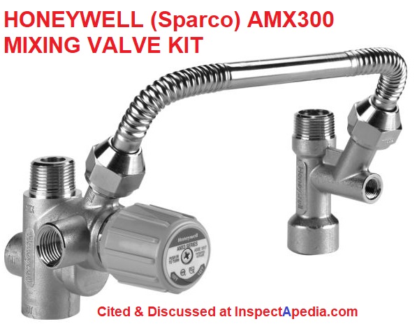
By contrast, an automatic mixing valve or compensating valve, such as those sold by Watts Regulator Co. or Sparco, includes a temperature sensing mechanism that automatically adjusts the amount of cold mixed in with outgoing hot water to maintain the desired output water temperature.
...
Mechanical Stop Temperature Limit for Water Temperature Control
Below we see a different type of mixing valve that is installed at the point of use by incorporating the mixing valve into the tub or shower control - shown below, using the Symmons TempControl 7-Series tub-shower control as an example.
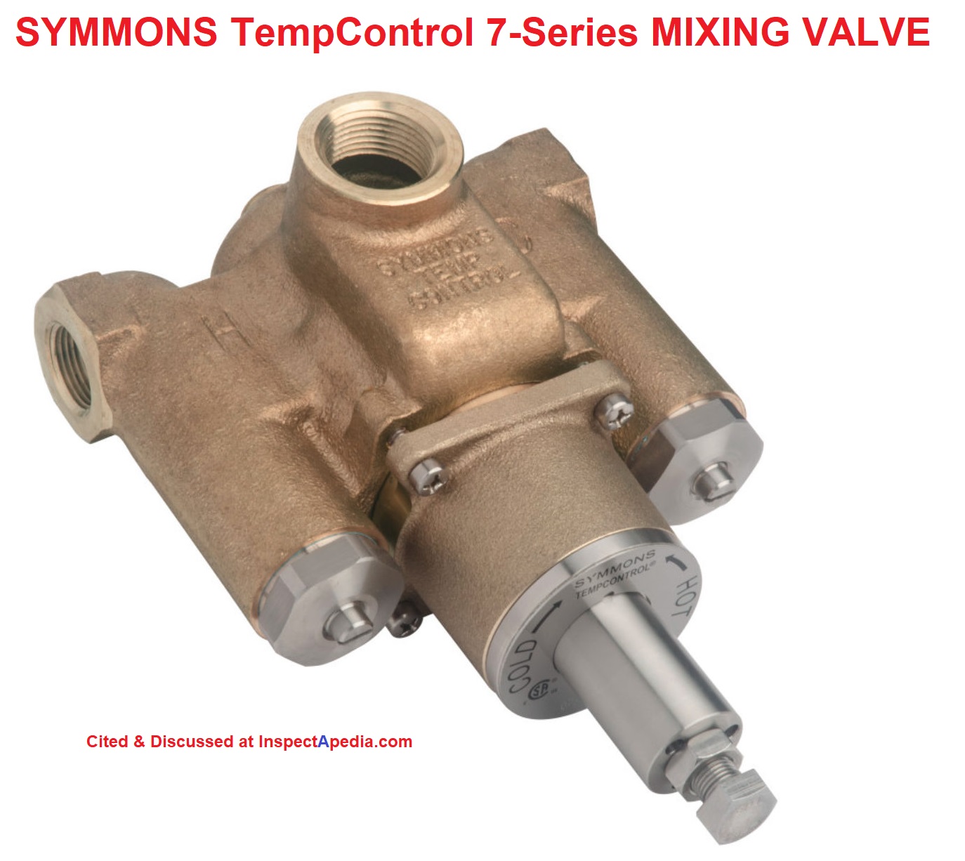
Unlike the independent Watts 70A tempering or mixing valve we showed first, you'll notice that when the temperature control valve is incorporated right into the point-of-use tub or shower control, for the examples we show here, the output water temperature setting adjustment is inside of the valve and is not readily adjusted by the user.
The control is usually a simple mechanical stop that prevents the user from turning the control to admit so much hot water as to risk a scalding burn.
Some disassembly is required to change the valve's temperature setting.
Also see POINT of USE BUILT-IN FIXTURE ANTI-SCALD VALVES at individual plumbing fixtures.
Below is an example of the interior cartridge that incorporates a mechanical stop or temperature limiting device.
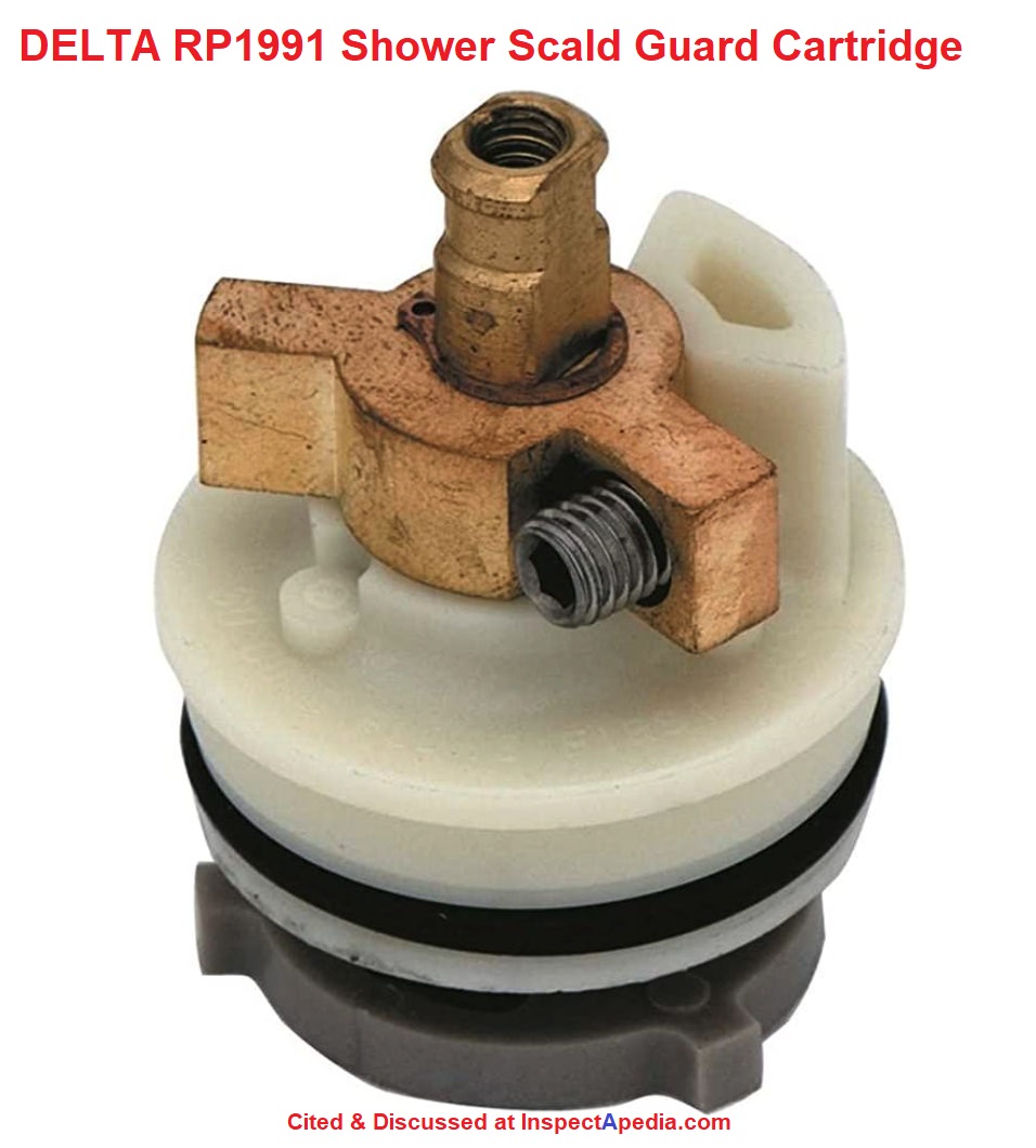
A temperature limit is set by a mechanical stop or limiting feature inside of a point-of-use fixture such as a tub or shower control.
An image of the internal parts of such as temperature stop is shown above, using the Delta Shower Scald Guard cartridge as an example.
The stop or temperature limit prevents the control handle from being turned further towards the "hot" setting, and is set by moving or adjusting a part inside the tub or shower control to a desired physical position that in turn is determined by first running hot water and measuring its temperature, then setting the single-lever tub or shower control to a point at or below the maximum temperature allowed.
Watch out: a mechanical limit stop only controls the hottest point towards which the tub or shower control knob can be turned.
It has no effect on the actual temperature of the hot and cold water that are entering the control. Therefore changes in either the cold water supply temperature or the hot water supply temperature vary for any reason, the output water temperature at the tub spout or shower head will vary as well.
Depending on location and thus local climate, the incoming cold water temperature at a building may be much colder in some seasons (winter in the northern hemisphere) than others.
Depending on independent adjustments at a water heater, depending as well on the type of water heater itself, the temperature of hot water supplied by the heater may not be constant.
For example, as the hottest water exits at the top of a tank-type water heater and cold incoming water enters at the water heater bottom, cold and hot water begin to mix inside the hot water tank.
As more hot water is used, more cold is mixed into the tank, and the temperature of water exiting at the water heater tank may begin to fall. The presence or absence of a temperature regulator at the hot water heater itself will also control the range of its output temperature.
...
Pressure Compensating or Regulating Device for Water Temperature Control
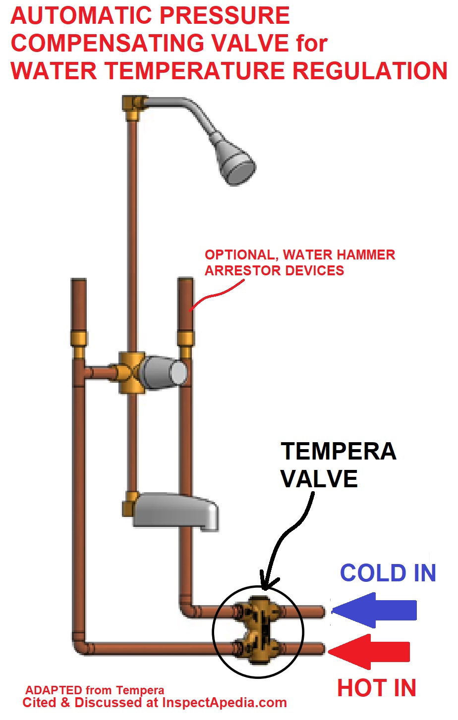
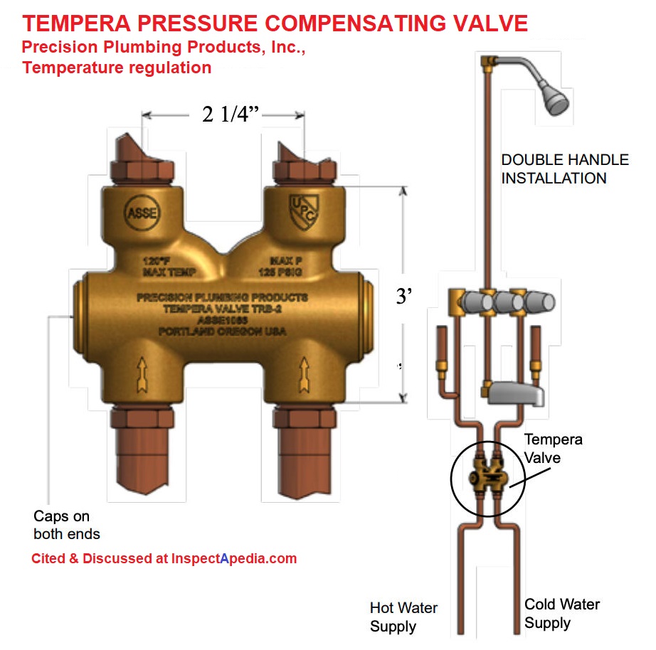
Shown above, using the Tempera TRB-2 pressure balancing valve as an example, is a piston-operated pressure regulator that monitors both hot and cold water supply pressure (not temperature) in an effort to regulate just how much hot and cold water are mixed together and then released to the tub or shower water outlet itself.
A pressure compensating valve will protect someone in the shower from getting a blast of very hot water if someone runs cold water nearby (such as flushing a toilet) and it may also protect the bather from a blast of cold water if hot water is run nearby while the user is in the shower.
As the manufacturer notes, check valves are required on the inlet side of this valve to prevent a possible cross-connection between hot and cold water piping.
Versions of a pressure regulating or pressure compensating valve for output water water temperature regulation can be used with both single-handle tub/shower controls and dual or double-handle type controls.
Note that this valve is regulating the mix of hot and cold water to avoid the effects of sudden changes in the pressure (and thus flow-rate) of either hot or cold water near the point of use, but it is not, itself, directly monitoring the actual temperature of water delivered to users at the fixture.
A point of source pressure balancing valve or automatic mixing valve (compensating valve, or a manual mixing valve) can be installed at or near the water heater, or at the tankless coil or other hot water source so that scald protection is provided even if the water heater is set to a high temperature.
...
Thermostatic Mixing Valve, Point of Use (or Point of Source)
 Thermostatic mixing valves use a temperature sensing device to dynamically adjust the mixture of hot and cold water flowing through the device as the temperature of either incoming hot or cold water changes.
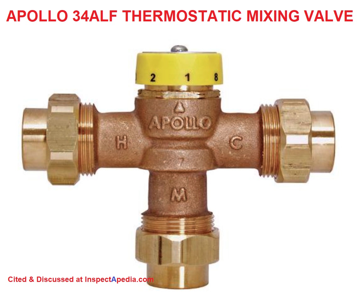
An example is the Apollo dual purpose thermostatic mixing valve whose product description we excerpt below:.
These valves can support either point of source (POS) OR point of use (POU) hot water temperature control and anti-scalding.
Shown in the illustration: The Apollo 34ALF thermostatic mixing valve intended for POS - Point-of-Source ASSE1017-Approved applications.
Apollo also offers the MVB and MVBLF series thermostatic mixing valves that can be used at POS or Point of Source as we describe below.
Watch out: when choosing a thermostatically controlled water temperature valve, be sure to read the product specifications with care. The Apollo POS 34ALF device looks much like the POU/POS 34BLF device in the store.
The Apollo MVB & MVBLF Series [Note that this is NOT the exact Apollo model shown above - Ed.] uses a shuttle/piston to control the volumes of cold and hot water required to deliver water at a predetermined temperature.
Cold water enters the mixing chamber above the top face of the shuttle, and hot water enters the lower face of the shuttle. T
he thermostatic element, which is positioned in the mixing chamber, is connected to the spring-loaded shuttle, which moves up and down in response to expansion and contraction of the element.
In the event of an increase in the temperature of either the hot or cold water supply, as the change commences to alter the temperature of the water in the mixing chamber, the thermostatic element immediately reacts by expanding.
This expansion moves the shuttle downwards, decreasing the opening area of the hot water supply, and increasing the opening for the cold water. this change in the volumes of the respective water supplies in the correct proportions, compensates for the change of temperature of the water in the mixing chamber, and a constant mixed water is maintained.
The sensitivity of the thermostatic element ensures instantaneous movement of expansion and contraction as necessary. In the event of a complete failure of the cold water supply, the ensuing expansion of the element shuts off the hot water supply completely.
For optimum performance it is imperative that the hot water inlet temperature has a minimum of 15°F above the desired outlet temperature.
The unit is equipped with a maximum temperature limit stop and handle locking mechanism to prevent inadvertent adjustment of the outlet temperature above 120°F . - source: Apollo IO Manual cited below
- Apollo DUAL PURPOSE THERMOSTATIC MIXING VALVE IO MANUAL [PDF] Model MB MVBLF ASSE 1017 Point-of-source & ASSE 1070 Point-of-use, Conbraco Industries Inc., 1418 Pearl St., Pageland SC 29728 USA Tel: 704-841-6000
Kohler's MasterShower® 1/2 in. NPT Thermostatic Rough In Valve with 10.9 GPM Flow Rate, shown below, is an example of a point of use or POU thermostatic mixing valve.
See the IO manual for this valve by Kohler listed at
ANTI SCALD VALVE LIFE, INSTALLATION, ADJUSTMENT INSTRUCTIONS - temperature limit stops & controls for sink, tub, shower, etc.
Excerpt:
CAUTION: Risk of scalding hazard.
This device has been
calibrated at the factory to ensure a safe maximum water
temperature.
Any variance in settings or water inlet
conditions from those used during factory calibration may
raise the discharge temperature above the safe limit, and may
present a scalding hazard.
Before completing installation, the installer must set the
maximum water temperature setting of this valve to minimize the
risks associated with scalding hazards according to ASTM F 444.
...
Anti-Scald & Thermostatic Mixing Valve Standards & Research
ASSE Hot Water Control Devices, Features, Examples |
Protection | Downstream Mixing |
Location | Final Temp Adjustment |
Use Example |
|
| ASSE Standard | Scald | Thermal Shock |
||||
| ASSE 1016 | YES | YES | NO | POU | YES | Individual |
| ASSE 1017 | NO | NO | YES | POS | NO | Hot water Distribution System 2 |
| ASSE 1062 | YES | NO | NO | POU | NO | Individual Fixture 3 |
| ASSE 1066 | NO | YES | YES | POU 4 | NO | Individual Fixture 4 |
| ASSE 1069 | YES | YES | NO | POU 5 | YES | Gang showers Sitz baths 5 |
| ASSE 1070 | YES | NO | YES | POU 6 | NO | Sink, tub, shower, bidet 6 |
| ASSE 1071 | YES | NO | NO | POU 7 | NO | Emergency wash station 7 |
Notes to the table above
The table above is adapted from ASSE's GUIDELINES for temperature control devices, cited in detail just below.
POU= Point Of Use, POS = Point Of Source
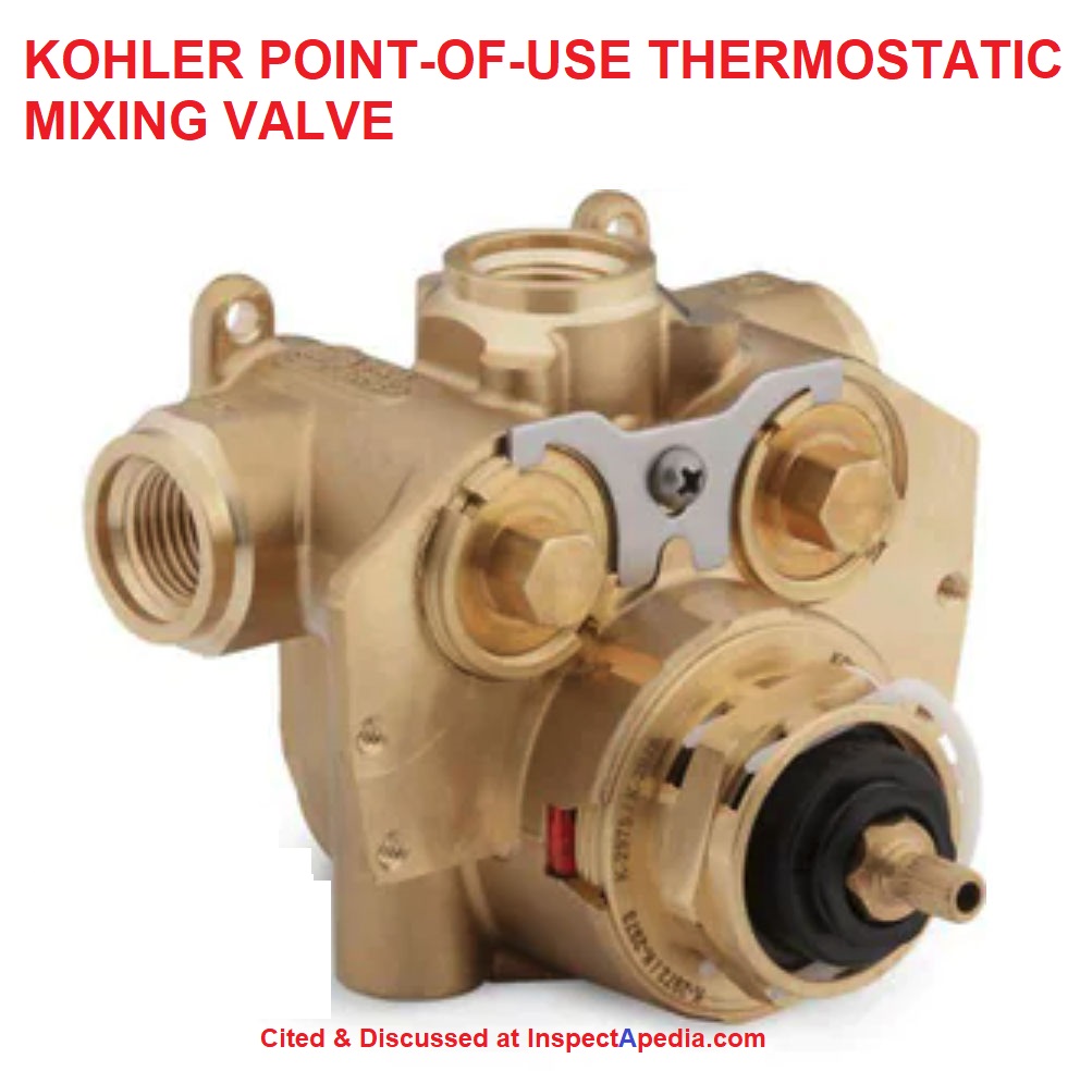
- ASSE 1016 devices are installed at or integral within an individual plumbing fixture control valve. See anti-scald protection requirements for individual shower or tub control valves required by UPC-408.3, IPC – 424.3, IRC- P2708.3 or NSPC-1015.6.
Example: KOHLER THERMOSTATIC MIXING VALVE - ASSE 1017 devices are installed at or near the water heater source. An additional downstream POS safety device is required.
Example: Caleffi 5321 Series THERMOSTATIC MIXING VALVE - ASSE 1062 devices are a temperature actuated flow
reduction control. These valves
are intended for use in-line with,
or are integrated into, individual
plumbing supply fittings such
as shower heads, bath, utility
faucets, sink and lavatory
faucets.
Example: - ASSE 1066 devices are installed in-line, just ahead of individual shower, tub, or sink faucets or controls.
Example: TEMPERA-THERM THERMOSTATIC/PRESSURE BALANCE CONTROL SPECIFICATIONS - ASSE 1069 devices are installed where the individual bather has no access to the temperature adjustment means
Example: Apollo MVBLF THERMOSTATIC MIXING VALVE - ASSE 1070 devices are installed near or integrated into individual plumbing fixture controls or fittings for a sink, lav, shower, tub or bidet. The device controls and limits outlet water temperature.
Example: Apollo DUAL PURPOSE THERMOSTATIC MIXING VALVE - ASSE 1071 devices are installed at emergency plumbing equipment such as an emergency eye-wash station and are intended to provide warm but never "hot" water, reverting to cold water if the hot water source fails.
---
- ASSE, GUIDELINES for TEMPERATURE CONTROL DEVICES in DOMESTIC HOT WATER SYSTEMS [PDF] ASSE International
18927 Hickory Creek Drive, Suite 220, Mokena, Illinois 60448
(708) 995-3019 | www.asse-plumbing.org, retrieved 2022/06/12 original source: https://www.asse-plumbing.org/media/5216/asse_guidelines_for_temp_control_devices.pdf
Excerpt from Executive Summary
Hot water from the tap accounts for more than 25 percent of all scald burns in children. The elderly and the physically impaired are at increased risk of scald burns also.
The attempt to prevent these scald injuries was the driving force that brought about the invention of temperature control devices. Each device covered by an ASSE product performance standard has specific applications as to where they are intended to be used.
However, over the past few years, ASSE International has been receiving calls from inspectors, installers, and others asking if certain types of devices are approved to be used in certain installations. The Authority Having Jurisdiction (AHJ) has the final approval of all installations, but one must be aware of the manufacturer’s installation requirements, which may exceed the prevailing code.
There also appears to be a misunderstanding of the use of devices listed to multiple standards.
For these reasons, the ASSE Board of Directors thought it was best to write a white paper to serve as a reference tool for adding clarity to where the devices should be installed.
The Task Group’s assignment was to develop a white paper that clearly explains where each temperature control device, within ASSE’s portfolio of product performance standards, should be used, and create an understandable reference tool that everyone in the plumbing industry can use.
The ASSE product performance standards for these devices are:
ASSE 1016-2011/ASME A112.1016-2011/CSA B125.16-11, Performance Requirements for Automatic Compensating Valves for Individual Showers and Tub/Shower Combinations
ASSE 1017-2009, Performance Requirements for Temperature Actuated Mixing Valves for Hot Water Distribution Systems
ASSE 1062-2006, Performance Requirements for Temperature Actuated Flow Reduction (TAFR) Valves for Individual Fixture Fittings
ASSE 1066-1997, Performance Requirements for Individual Pressure Balancing In-Line Valves for Individual Fixture Fittings
Excerpt:
Performance Requirements for Individual Pressure Balancing In-Line Valves for Individual Fixture Fittings Automatic pressure balancing in-line valves are used to equalize incoming hot and cold water line pressures for minimizing mixed water temperature variations due to pressure fluctuations when used with a mixing valve or two handle valve set.
They are not designed to limit the maximum outlet temperature at the point-of-use. The device is intended for use in individual plumbing fixtures fittings such as shower heads, bath utility faucets and sink and lavatory faucets.
ASSE 1069-2005, Performance Requirements for Automatic Temperature Control Mixing Valves
ASSE 1070-2015/ASME A112.1070-2015/CSA B125.70-15, Performance Requirements for Water Temperature Limiting Devices
ASSE 1071-2012, Performance Requirements for Temperature Actuated Mixing Valves for Plumbed Emergency Equipment - ASSE, UNDERSTANDING POTENTIAL WATER HEATER SCALD HAZARDS, [PDF] (2012) American Society of Sanitary Engineering Scald Awareness Task Group, ASSE International Office - 901 Canterbury Road, Suite A - Westlake, Ohio 44145 USA Tel: 440.835.3040 Web Site: http://www.asse-plumbing.org
- Bhatia, A. DESIGN CONSIDERATIONS for HOT WATER PLUMBING [PDF] (2014) CED, Continuing Education and Development, Inc.
9 Greyridge Farm Court
Stony Point, NY 10980
P: (877) 322-5800
F: (877) 322-4774
info@cedengineering.com - retrieved 2022/06/12, original source: https://www.cedengineering.com/userfiles/Design Considerations for Hot Water Plumbing.pdf
Excerpt:
Heating water is typically the second largest use of energy in residential and commercial buildings (after space heating and cooling).
Despite its resource intensity, the hot water delivery system is seldom an area of significant focus when constructing a building.
As a result, many buildings today are built with poor performing, inefficient hot water delivery systems that take minutes to deliver hot water to the point of use and waste large amounts of energy and water in the process. The key to proper water heating system design is to correctly identify the quantity, temperature and time characteristics of the hot water requirement.
The goal is to reduce hot water wait time to 10 seconds or less, which is considered acceptable for public lavatories. A wait time of 11 to 30 seconds is considered borderline and a wait time of 30 seconds or more is unacceptable. - Bynm, D. et als, DOMESTIC HOT WATER SCALD BURN LAWSUITS, THE WHO, WHAT, WHEN, WHY, WHERE, HOW [PDF] Dr. D. Bynum Jr., Vernon L. Petri, Esq., John T. Myers, paralegal, Seminar and Technical Paper for the 25-28 Oct 98 Annual ASPE Meeting at the Indianapolis Convention Center, Indianapolis IN, websearch 09/21/2010,original source: http://media.wattswater.com/F-H20LS-Reprint.pdf [Large PDF]
- Davila, Alejandro R., Carmen E. Cejudo Marmolejo, and Katherine LM Stoughton. DOMESTIC HOT WATER TEMPERATURE MAINTENANCE TECHNOLOGY REVIEW [PDF] (2021). U.S. Department of Energy, Pacific Northwest National Laboratory, retrieved 2022/06/12 original source: https://www.osti.gov/servlets/purl/1813897
- Lowitz, Greg, COLD SHOWER MYSTERY SOLVED [PDF] (2014) Buildera, 520 El Camno Real Ste. 150-415, Redwood City CA 94063, USA, Tel: 1-888-888-3111, Web: www.buildera.com - retrieved 2022/06/12 original source: https://www.researchgate.net/profile/Greg-Lowitz/publication/271205793_Cold-Shower_Mystery_Solved_Multi-Channel_Data_Loggers_Improve_Forensic_Analysis_of_Complex_Domestic_Hot-Water_Complaints_Buildera_Application_Note_AN-14001/links/54c15bc30cf2d03405c53f6b/Cold-Shower-Mystery-Solved-Multi-Channel-Data-Loggers-Improve-Forensic-Analysis-of-Complex-Domestic-Hot-Water-Complaints-Buildera-Application-Note-AN-14001.pdf
- Watts Water Technologies Powers, ASSE 1016, 1069 & 1070 PRESENTATION [PDF] Watts, Powers, Power point presentation, retrieved 2022/06/17 original source: http://media.wattswater.com/powers_asse_review.pdf
- Weaver, Alissa M., Harvey N. Himel, and Richard F. Edlich. "Immersion scald burns: strategies for prevention." The Journal of emergency medicine 11, no. 4 (1993): 397-402.
Abstract:
Tap water scald burns are common injuries to persons with disabilities, young children, and the elderly.
A case is reported of an elderly woman with a physical and neurological handicap who while bathing received partial and full thickness (tap water) scald burns covering 20% of her total body surface area.
This life-threatening injury could have been prevented with a Shower Safe, Inc. temperature-controlling water valve.
Excerpt:
Obviously, this mixing valve system offers no reliable control of water temperature.
...
Continue reading at ANTI-SCALD VALVE INSPECTION or select a topic from the closely-related articles below, or see the complete ARTICLE INDEX.
Or see these
Recommended Articles
- ANTI SCALD VALVES & TEMPERATURE CONTROL / MIXING VALVES - home
- ANTI-SCALD VALVE INSPECTION
- ANTI SCALD VALVE INSTALLATION & ADJUSTMENT MANUALS
- ANTI SCALD VALVE PROTECTION, Best Practices
- ANTI SCALD VALVE for USE ON STEAM BOILERS
- ANTI SCALD VALVE at TANKLESS COIL
- ANTI-SCALD WATER TEMPERATURE CONTROL TYPES
- MANUAL ANTI-SCALD TEMPERING VALVES
- POINT of USE BUILT-IN FIXTURE ANTI-SCALD VALVES
- POINT of USE ANTI-SCALD WATER TEMPERATURE ADJUST Pfister - how to adjust a point of use anti-scald valve
- SAFETY WARNINGS for ANTI-SCALD VALVES
- HOT WATER ANTI-SCALD REGULATIONS
- WATER HEATER TEMPERATURE ADJUSTMENT CONTROLS - home - all types of water heater temperature controls & adjustment devices
Suggested citation for this web page
ANTI-SCALD WATER TEMPERATURE CONTROL TYPES at InspectApedia.com - online encyclopedia of building & environmental inspection, testing, diagnosis, repair, & problem prevention advice.
Or see this
INDEX to RELATED ARTICLES: ARTICLE INDEX to WATER HEATERS
Or use the SEARCH BOX found below to Ask a Question or Search InspectApedia
Ask a Question or Search InspectApedia
Share this article:Questions & answers or comments about anti scald devices and mixing valves on hot water systems
Try the search box just below, or if you prefer, post a question or comment in the Comments box below and we will respond promptly.
Search the InspectApedia website
Note: appearance of your Comment below may be delayed: if your comment contains an image, photograph, web link, or text that looks to the software as if it might be a web link, your posting will appear after it has been approved by a moderator. Apologies for the delay.
Only one image can be added per comment but you can post as many comments, and therefore images, as you like.
You will not receive a notification when a response to your question has been posted.
Please bookmark this page to make it easy for you to check back for our response.
IF above you see "Comment Form is loading comments..." then COMMENT BOX - countable.ca / bawkbox.com IS NOT WORKING.
In any case you are welcome to send an email directly to us at InspectApedia.com at editor@inspectApedia.com
We'll reply to you directly. Please help us help you by noting, in your email, the URL of the InspectApedia page where you wanted to comment.
Citations & References
In addition to any citations in the article above, a full list is available on request.
- Our recommended books about building & mechanical systems design, inspection, problem diagnosis, and repair, and about indoor environment and IAQ testing, diagnosis, and cleanup are at the InspectAPedia Bookstore. Also see our Book Reviews - InspectAPedia.
- In addition to citations & references found in this article, see the research citations given at the end of the related articles found at our suggested
CONTINUE READING or RECOMMENDED ARTICLES.
- Carson, Dunlop & Associates Ltd., 120 Carlton Street Suite 407, Toronto ON M5A 4K2. Tel: (416) 964-9415 1-800-268-7070 Email: info@carsondunlop.com. Alan Carson is a past president of ASHI, the American Society of Home Inspectors.
Thanks to Alan Carson and Bob Dunlop, for permission for InspectAPedia to use text excerpts from The HOME REFERENCE BOOK - the Encyclopedia of Homes and to use illustrations from The ILLUSTRATED HOME .
Carson Dunlop Associates provides extensive home inspection education and report writing material. In gratitude we provide links to tsome Carson Dunlop Associates products and services.
 |
HOME | ABOUT | ASK a QUESTION | CONTACT | CONTENT USE POLICY | DESCRIPTION | POLICIES | PRIVACY | |
| © 2026 - 1985 Publisher InspectApedia.com - Daniel Friedman | |||||||||