
 Electrical Resistance vs Heat Generated
Why lower electrical resistance produces more heat
- POST a QUESTION or COMMENT about thermostat heat anticipator circuits & controls.
What is the relationship between electrical resistance and heat generated by a wire, circuit or electrical device?
This article uses an older Honeywell T87 type thermostat heat anticipator device to explain the relationship between electrical resistance and heat generated by a wire when current flows through it.
In the related article series we explain how adjusting the heat anticipator pointer changes the heat output of the anticipator that in turn changes the behavior of the room thermostat to turn the burner off sooner or later with respect to the actual room temperature.
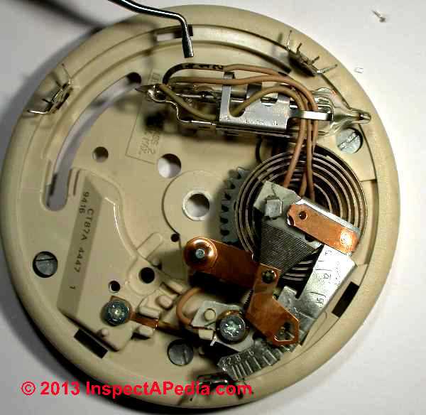
Our page top photo illustrates key parts of a traditional room thermostat including the temperature sensing device, thermostat switch, and the heat anticipator assembly.
InspectAPedia tolerates no conflicts of interest. We have no relationship with advertisers, products, or services discussed at this website.
- Daniel Friedman, Publisher/Editor/Author - See WHO ARE WE?
Why Higher Current (Amps) OR Lower Electrical Resistance Can Generate More Heat
This article explains while it may not be the case in other electrical circuits, less electrical resistance across a room thermostat's heat anticipator winding will generate more heat that in turn will cause a room thermostast to turn off sooner.
Separately at HEAT ANTICIPATOR OPERATION we explain that as used in some room thermostsats, the heat anticipator is a tiny electrical heating element inside the room thermostat.
This anticipator adds warmth to the thermostat's room temperature sensor in anticipation of the additional heat will come out of radiators or baseboards after the heating system has shut off.
When the heat anticipator itself produces more heat it turns the heating system off SOONER.
When the heat anticipator produces less heat it turns the heating system off later, so the heat stays on LONGER.
Why Higher Electrical Resistance Means Less Heat is Generated in a Heat Anticipator Circuit
An InspectApedia reader asked:
I have an OLD ('70s) honeywell class 2 lr1620 and the anticipator dial has an arrow indicating LONGER in the direction of the HIGHER numbers (like the ones you show above).
It is a completely different dial with a metal connector used to set the Amps using your fingernail.
It would seem that the direction of the "LONGER" arrows in both units is not a mistake by Honeywell.
My heating unit is reaching temp, shutting down (mercury switch tipping), then failing to start up again, despite the mercury switch being clearly engaged.
I thought it might be the anticipator which is set on 0.4. Any ideas? Thanks Adam. Melbourne Australia boogweig@gmail.com - 17 June 2015 Adam Williams
Answer by Daniel: Less resistance (shorter wire length) in a thermostat heat anticipator means turn the heating system off sooner.
Bottom line: Your thermostat's heat anticipator Amps scale is correct.
Moving the thermostat's heat anticipator pointer to the left or the direction of the arrow below the word "LONGER" in our photo and thus towards higher current (Amps) numbers means that the heat anticipator will generate less heat to warm the thermostat's temperature sensor, so the building heating system will stay on longer.
Below we'll explain how and why adjusting the heat anticipator to provide less resistance produces more heat at the heat anticipator.
Confustion about Where the word LONGER Appears on the Heat Anticipator Scale
First let's clear up some confustion about the heat anticipator scale and where the word "LONGER" - meaning longer heat on cycle - appears.
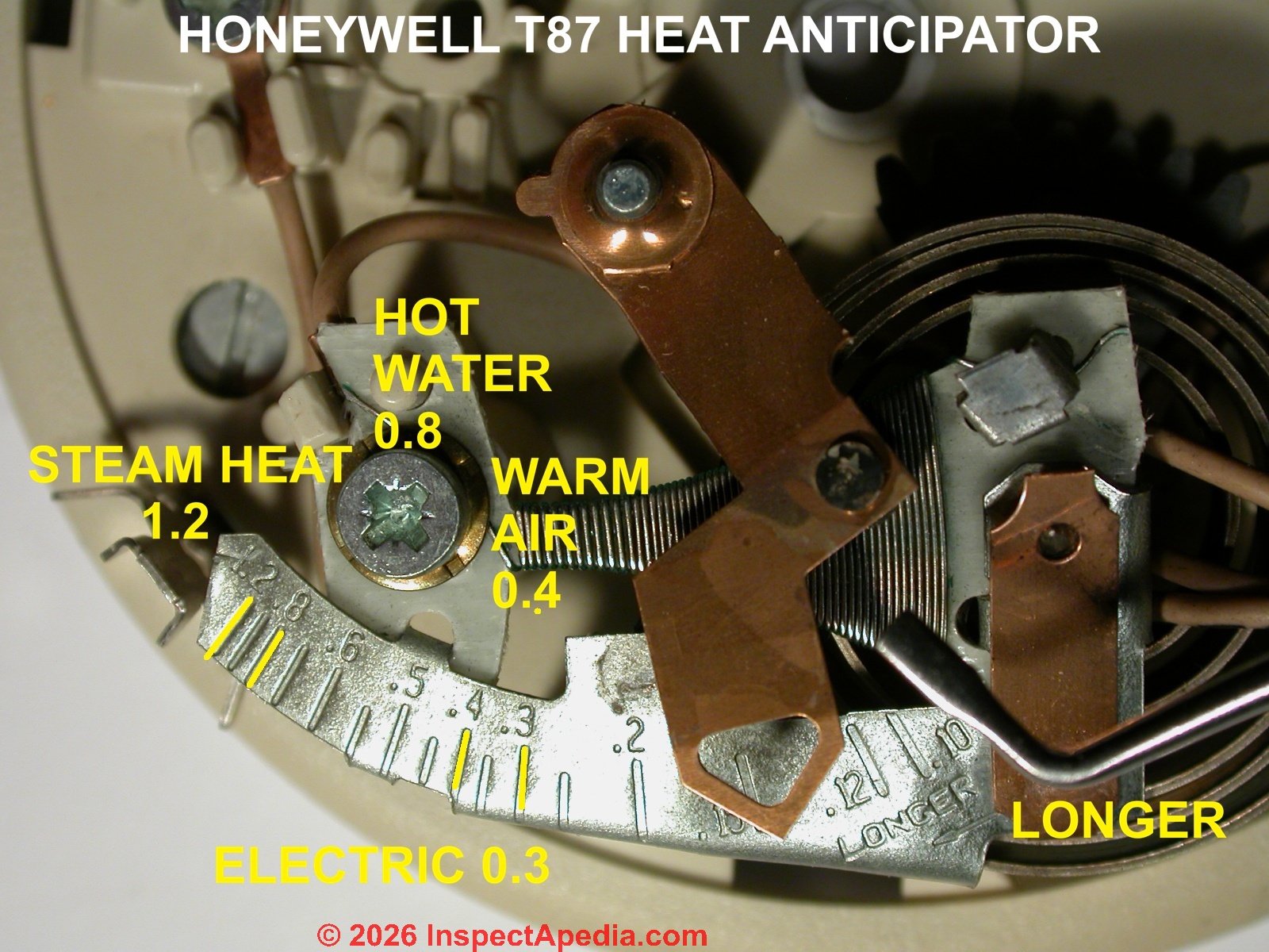
Below I show an enlargement of the right end of the heat anticipator scale showing the hard-to-see arrow pointing to the left below the word "LONGER".
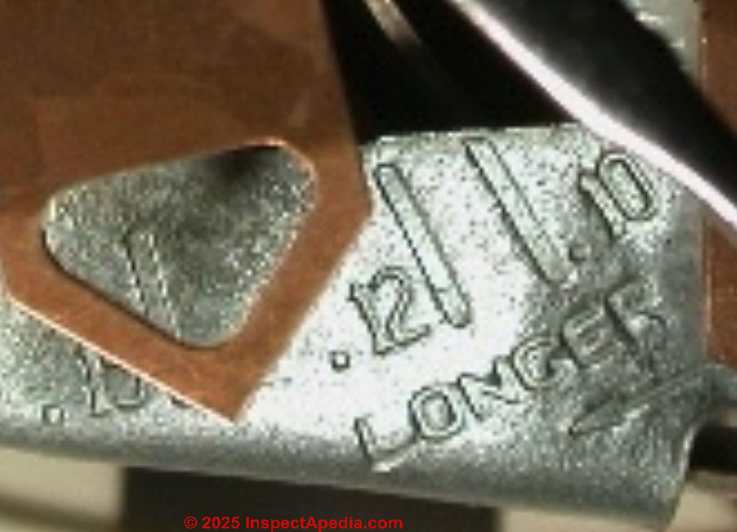
"LONGER" is seen at the low-number end of the current or Amps scale on this thermostat heat anticipator. The location of the word LONGER at the right end of the scale (lower current numbers) is what causes some confusion.
But a closer examination this Honeywell T87 Thermostat will show although the word "LONGER" stamped at the low-number right-end of the scale, below that word there is also an arrow pointing towards the higher numbers on the heat anticipator scale.
The arrow tells us that moving the slider to the left towards higher current numbers means less heat will be generated by the anticipator so the building heat will stay on LONGER.
Honeywell was saying: for longer heat-on times move the pointer in the direction of the arrow (to the left in the photo, towards the higher Amps numbers (more current) along the heat anticipator scale).
I think Honeywell printed Longer where they did because that's where the scale's design gave room for the text. Don't miss that arrow below the word LONGER.
Why Does Less Resistance Produce More Heat in a Thermostat Heat Anticipator Circuit?
At the higher current end of its scale, the heat anticipator winding more current is flowing and electrical resistance is less (keeping voltage unchanged).
Details of why we get this heating effect are at JOULES HEATING LAW but in general, for a fixed voltage V (24VAC in a thermostat circuit) more current (Amps) I flows when resistance R is lower.
From Joule's Law P = I2 R power (or in this case heat) P generated by a resistor (the anticipator wire winding) is proportional to the product of current I squared I2 times resistance R.
LOWER electrical resistance R will produce a higher current I in the circuit (keeping voltage unchanged) that causes greater power dissipation as heat. The amount of heat generated is proportional to the current squared and the resistance.
Notice that it's the I or current value (Amps) that is squared in this equation, giving it more weight in the formula than R (Resistance).
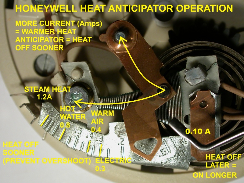
Notice also that the adjustment arm of the heat exchanger is basically moving an electrical contact so as to either increase or decrease the length of wire through which electrical current will flow.
In a photo above my white arrow shows the direction of current flow. You can see that the length of the wire through which current flows will change as we move the slider.
If we keep the voltage unchanged and just change the length of a wire, a longer wire produces more resistance to current flow (resistance in Ohms) and a shorter wire produces less resistance to current flow.
Physics and electrical texts and online forums state that in general Less Electrical Resistance = More current flow = More heat is produced and conversely, More Electrical Resistance = Less current flow = less heat is produced.
But in the heat anticipator circuit as we move the slider towards the longer side of the scale, towards higher current or Amps numbers, the resistance falls but power goes down as well so the wire will take longer to heat up and thus the building heater will stay on longer.
Special Properties of Wire Used on a Thermostat Heat Anticipator
The use of a thin nichrome or chromium wire in a heat anticipator is chosen because at the same total resistance of the electrical circuit, that wire will both reach a higher wire-temperature than would a thick copper wire, and it will also resist burning up when heated.
That's true even though that thin chromium wire is itself considered "high resistance" wire - a fact that can lead us astray.
To get the same total resistance the copper wire would be about 50x longer than the chromium wire and would thus be able to dissipate 50x more heat over its length than would the chromium wire.
Example: the heat given off by a resistor is its energy loss I2R. Keeping Voltage AND Resistance fixed, I = Voltage / Resistance and heat produced is given by (V / R)2 (R)= V2 / R.
When we lower the resistance R we will see more more heat generated in the wire.
Really? That's counter-intuitive to the general observation that "if it's easier for electricity to flow through a wire then it loses less energy so gives off less heat.
Here's what an electronics forum discussion explained: two things can be true at once:
Any given resistor can dissipate the same amount of power. It just depends on the product of voltage and current
P = V x I or Power = Volts x Amps
Since V = I x R and I = V / R the expression for the power can be rewritten as
P = V x (V / R) or
P = V2 / R
or as
P = (I x R) x I or
P = I2 x R
The first equation (P = V x I ) suggests that a higher resistance would be better [to obtain a higher current]
while the second (P = I2 x R ) shows that a lower resistance would be better [to obtain a higher voltage or less voltage drop]
So it depends on the application if it is easier to generate a higher current or a higher voltage and you have to choose the resistor accordingly.
Why is the Thermostat Heat Anticipator Wire Wrapped in a roughly Triangular Shape?
 An expert reader N.D. who asked to remain otherwise anonymous
noted that
An expert reader N.D. who asked to remain otherwise anonymous
noted that
The design of the anticipator is interesting because it is a non-linear function of the stting. For mathematical simplicity, consider an anticipator where the current is 1 Amp, the resistance is 1 Ohm, and the power is 1 Watt.
If the current (Amps) is cut in half, power goes down to one fourth (current squared times resistance).
To maintain the Watt of heating, the resistance needs to go up to 4 Ohms. This means that the resistance needs to be a parabolic function of the Amps setting on the scale.
A glance at the anticipator shape and winding shows that it is indeed a nichrome wire wound on a flred (roughly triangular) mandrel instead of being wound on a regular diameter cylinder as is the case with solenoids.
If the resistance werea linear function of the setting on the scale (bottom of our photo), the numbers would be so crammed together at one end of the scale that it would be unreadable.
Example Heat Anticipator Numbers
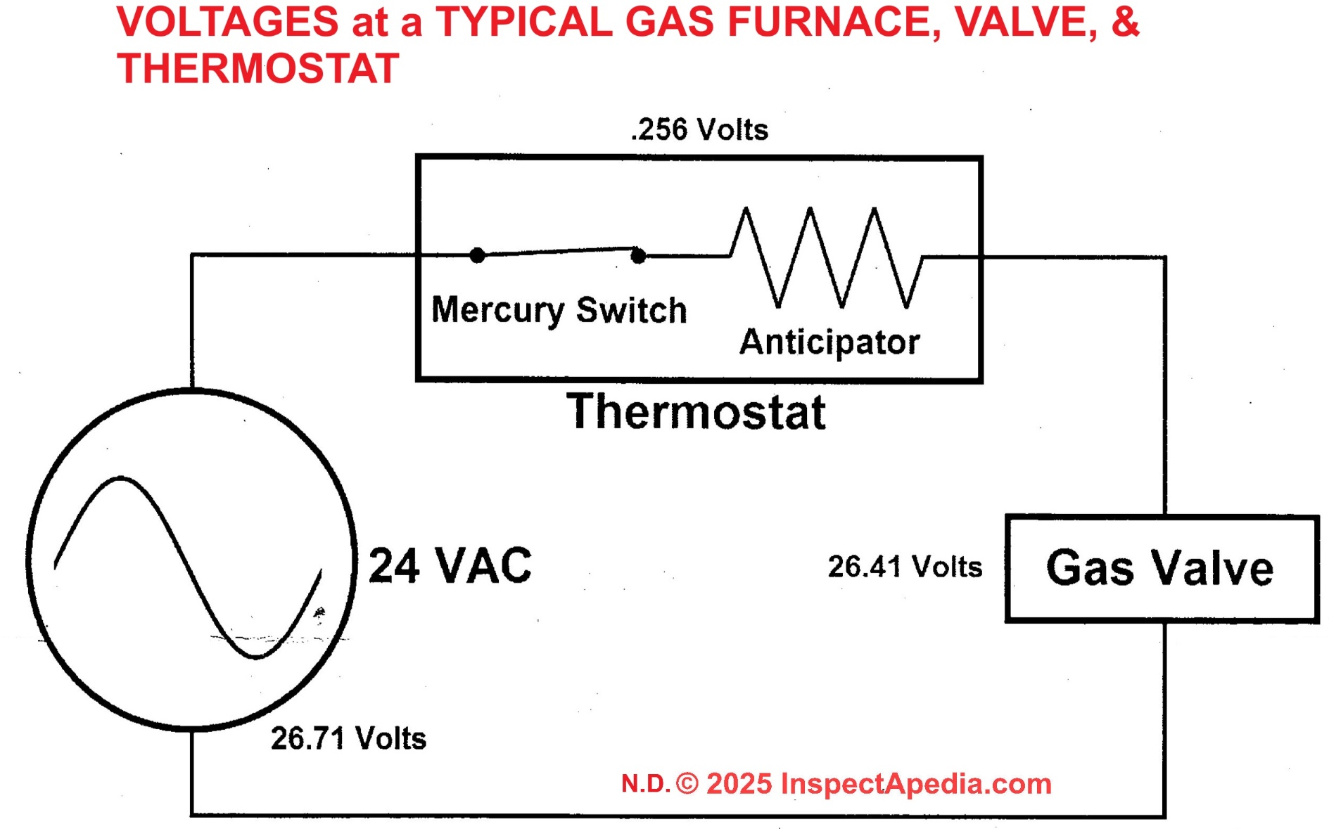
A properly operating gas furnace uses a gas valve drawing 0.57A.
The heat anticipator is also set to 0.57A and at this setting will drop 0.256 VAC across the thermostat.
The resistance of the heat anticipator is therefore about 0.5 Ohms and its power dissipation (heat) is about 0.16 watts (1/6 watt).
Heat Anticipator Device Failure or Burn-Up Warning
Gas valve installation manuals warn the installer not to short out the terminals on the gas valve lest they burn out the thermostat's heat anticipator. A dead short across the gas valve terminals would send 24VAC right across the thermostat.
With a heat anticipator resistance of 0.5 Ohms, the power dissipation would exceed 1000 watts! The transformer itself can't of course provide this much power, but it will put out enough to burn out the anticipator.
For a gas valve to draw 0.57A on a 24VAC circuit it requires an impedence of 42 Ohms. That's about 80 times the resistdance of the heat anticipator. The combination of the 24VAC poer supply and the gas valve provide current to the thermostat and the heat anticipator's setting has only a slight effect on that current flow.
The following is more speculative.
The presence of a discrete resistor in the thermostat complicates this matter. It is probably in parallel with the heat anticipator so that the building heater will still run if the heat anticipator has burned out [we have not checked this - Ed.].
The resistor may be in series to provide a minimal resistance even when the slider is adjusted to zero, avoiding the problem of loss of building heat should the anticipator burn up.
Watch out: a transformer (over-voltage) or gas valve defect or trying to use a 24V-rated room thermostat to directly control or switch equipment operating at 120V or 240V can cause the heat anticipator in a room thermostat to burn up. The result may be at least a heating system that short-cycles or complete loss of heat.
Properly, and as you'll read throughout Honeywell's thermostat manuals, the heat anticipator should be set to match the current draw of the heating system's primary control. And you need to use a line-voltage thermostat to control line voltage heaters such as electric heat.
Research: Which Heats-up more: high-resistance wire or low-resistance wire circuits?
- Electrical Engineering on Stack Exchange, Is higher or lower resistance wire able to heat up more? Are there other factors? [Web page] Electrical Engineering StackExchange, retrieved 2017/10/31, original source: https://electronics.stackexchange.com/ questions/219212/is-higher-or-lower-resistance-wire-able-to-heat-up-more-are-there-other-factors - revise link & title 2025/07/14|
Notice that the engineers point out arguments that diverge and that a higher wire temperature doesn't necessarily mean more total heat generated (e.g. a light bulb filament is hotter than but gives less toatl heat output than an electric stove burner).
- Physics Forum, Resistance of a heating element [Web page] Physics Forums, retrieved 2017/10/30, original source: https://www.physicsforums.com/threads/resistance-of-a-heating-element.5608/ and reviewed 2025/07/14
Excerpt:
The heat a resistor produces is the energy loss given by I2 R.
If you assume a fixed voltage and resistance, then I= V/R so the heat produced is given by (V/R)2(R)= V2/R.
By golly it is true! LOWER resistance will produce a higher current and that is more important than the resistance! Lower resistance will produce more heat.
And Paraphrasing, adapting, and commenting on the above discussion: If the electrical resistance in a circuit is very low, electrons can move right through without losing much energy [in the form of heat], whereas if the resistance is high the electrons meet resistance, lose energy, and that lost energy is given off as heat. (P=VI & V= IR).
But we also see that P=VI is not a measure of heat, it's a measure of power.
The heat given off by a resistor is I 2 R
When we keep the same voltage (24VAC on a thermostat heat anticipator circuit) if we keep the same resistance (Ohms) then
the heat produced is given by (V/R)2 (R) = V2 R.
Dividing the square of the voltage by the circuit resistance means that as we lower the resistance we see more heat produced.
Why does this make sense for the little heater in the thermostat's heat anticipator? Because for that circuit, the little heater wire is the only thing in the circuit. Nothing else is limiting current flow through that little wire, so it gets warm - or even hot.
Conversely, in a house wire circuit that say powers a light bulb or a toaster, the bulb or toaster is providing a much higher resistance than the circuit wire bringing power to that device. So the device heats up enormously more than the circuit wire itself. (And of course the circuit wire is #14 or #12 coppe wire while the heating up wires in the light bulb (tungsten) or toaster (nichrome wire) are quite thin.
Here are the most-helpful comments of this explanatory discussion:
If you use a very large resistance for the element, it drops the majority of the voltage, but limits the current and you get little heating in the element.
If you use a very small resistance, most of the voltage is dropped across the internal resistance of the battery, and you get little voltage across the element and you get little heating.
If you plot the heat (wattage usage) of the element vs the resistance of the element, you will find that the maximum occurs when the Element's resistance equals that of the internal resistance of the source.
This is also the reason for impedance matching in electronic circuits; The maximum signal strength is transfered when the impedance of output and input match.
Sooo,
If you use a very small resistance AND the circuit design is such that the voltage drop is across the resistance of the heating-wire-circuit, [nothing else in the circuit is limiting current flow] you will get more heating. That's what we have in a heat anticipator internal-nichrome-wire-heater device.
The comparatively large #18 copper thermostat wire has maybe 50 times less resistance than the short length of nichrome wire in the thermostat heat anticipator's heater. So the 24VAC fed into the little heater warms up the nichrome wire - where it's functioning similarly to the filament in a light bulb fed by #14 copper wire in a house circuit.
When we adjust the heat anticipator to a higher Amps number we shorten the nichrome wire to lower its resistance still further, more current is pushed through it and it gets still hotter. - Ed.
Does Setting the Thermostat Heat Anticipator to a Higher Number Cause our Heating System to Run Longer?

Yes, higher numbers on the anticipator scale means heat runs longer (and heat anticipator heats-up less).
Let's look at our little heat anticipator mechanism shown above.
On all of Honeywell's heat anticipators, either by the direction of an arrow or by the imprint of the word LONGER we are told that the LOWER Amps (current) numbers on the heat anticipator scale will run the heat longer.
That's because at higher currents (Amps) settings we are moving the contact along the heat anticipator winding to use more of its wire, increasing the heat anticipator circuit resistance, so less heat is generated in the wire that comprises the heat anticipator's actual heater.
- When the heat anticipator generates less heat
(lower Amps on the scale, lower current, less heat generated) running through less of its own nichrome wire length, sees lower resistance, so it is doing more pre-warming the thermostat's temperature sensor so building heat shuts off sooner or the building heater runs for a shorter time.
- When the heat anticipator generates more heat
(higher Amps on the scale, more current, more heat generated) it is running through more of its own nichrome wire length, sees higher resistance, so it is doing less pre-warming of the thermostat's temperature sensor so heat shuts off later or the building heater runs for a longer time.
As we slide the heat anticipator pointer to the left (towards 1.2A - the highest number on the scale), keeping voltage the same, current will run through a longer length of nichrome wire - the total resistance will be more, and heat generated by the heat anticipator will be less - the heating system will stay on longer.
When the heat anticipator generates less heat (lower Amps) it pre-warms the thermostat's temperature sensor less so heat shuts off later,or the heater runs for a longer time.
As we slide the heat anticipator pointer towards the right (towards 0.10A), current has to run through a longer length of nichrome wire - resistance will be more, the current flow will be less, and the heat generated by the heat anticipator will be less.
When the heat anticipator generates less heat it is warming the thermostat's bimetallic spring less, so the thermostat thinks the room is cooler, so the building heating system will run slightly longer and a bit more heat will be delivered to the building from its heating system.
Basically, electrical resistance (measured in Ohms) is the resistance of a wire to the flow of electrical current. Electrical energy is needed to push current (measured in Amps) through a the resistance of a wire. That electrical energy will be dissipated in the form of heat, heating up the wire in the process.
This heating is called Joule heating (James Prescott Joule) or ohmic heating or resistive heating.
The formula for Joule Heating (P) (JOULES HEATING LAW) tells us that the amount of heat generated by a wire is proportional to the product of its resistance and the square of the current passing through it, or
P = I2 R
P = power or energy (converted from electrical energy to heat) or the heat produced by a resistor (or wire)
I = current (amps) through the resistor or wire
R = resistance (Ohms)
Ohm's Law (OHM's LAW) says that the current through a wire is proportional to the voltage, or
I = V / R
I = current through the wire (in Amps)
V = voltage measured across the wire (in Volts)
R = resistance of the wire (in Ohms)
If we keep Voltage unchanged and Resistance unchanged
I = V/R or Current = Volts / Resistance,
and looking at the two formulas we just gave, we can substitute (V/R) for I and the
heat produced is
(V/R)2 x R = V2 / R
Which tells us that lower resistance (R) will produce higher current. Therefore lower resistance produces more heat.
So why don't low-resistance building electrical wires get really hot? Because most of the voltage drop is across the load (light bulb, toaster, dishwasher) rather than across the wire.
It is the resistance of the load, the appliance, light bulb, or whatever the electrical circuit is powering that limits current flow through the electricl wire in a normal building circuit.
In fact if the appliance has a short circuit or failure so that it begins to pass more current than is safe for the circuit, the circuit breaker is designed to open or trip to stop the flow of electricity.
Details about electrical resistance heating
Other readers commented that previously we had not properly explained the properties of electrical resistance and that longer heat on times would be associated with less heat output from the heat anticipator that would occur at higher rather than lower resistance.
The wire wound resistor used in a heat anticipator converts some electrical power into heat. The electrical resistance of a conductor is responsible for the generation of heat.
Joules Law Describes Joule Heating or ohmic heating or resistive heating on this separate page.
This discussion is now found at JOULES HEATING LAW
...
...
Continue reading at HEAT ANTICIPATOR OPERATION or select a topic from the closely-related articles below, or see the complete ARTICLE INDEX.
Or see these
Recommended Articles
- DEFINITION OF AMPS, ELECTRICAL CURRENT
- DEFINITION OF OHMS, ELECTRICAL RESISTANCE
- HEAT ANTICIPATOR OPERATION
- HEAT ANTICIPATOR EFFECTS on ROOM TEMPERATURE
- ELECTRICAL RESISTANCE vs HEAT GENERATED
- FURNACE CONTROLS & SWITCHES
- HEAT ANTICIPATOR ADJUSTMENT
- HEAT ANTICIPATOR ADJUSTMENT - T87
- HEAT ANTICIPATOR SET & TEST by AMMETER
- HEAT ANTICIPATOR THERMOSTAT SOURCES
- JOULES HEATING LAW - Definitions & an explanation of resistive heating or resistance heating, ohmic heating, & Joules Heating
- TEMPERATURE RESPONSE of ROOM THERMOSTATS
Suggested citation for this web page
ELECTRICAL RESISTANCE vs HEAT GENERATED at InspectApedia.com - online encyclopedia of building & environmental inspection, testing, diagnosis, repair, & problem prevention advice.
Or see this
INDEX to RELATED ARTICLES: ARTICLE INDEX to HVAC THERMOSTATS
Or use the SEARCH BOX found below to Ask a Question or Search InspectApedia
Ask a Question or Search InspectApedia
Share this article:Try the search box just below, or if you prefer, post a question or comment in the Comments box below and we will respond promptly.
Search the InspectApedia website
Note: appearance of your Comment below may be delayed: if your comment contains an image, photograph, web link, or text that looks to the software as if it might be a web link, your posting will appear after it has been approved by a moderator. Apologies for the delay.
Only one image can be added per comment but you can post as many comments, and therefore images, as you like.
You will not receive a notification when a response to your question has been posted.
Please bookmark this page to make it easy for you to check back for our response.
IF above you see "Comment Form is loading comments..." then COMMENT BOX - countable.ca / bawkbox.com IS NOT WORKING.
In any case you are welcome to send an email directly to us at InspectApedia.com at editor@inspectApedia.com
We'll reply to you directly. Please help us help you by noting, in your email, the URL of the InspectApedia page where you wanted to comment.
Citations & References
In addition to any citations in the article above, a full list is available on request.
- [1] Proliphix Corporate Headquarters [Website: proliphix.com] , 3 LAN Drive Suite #100, Westford, MA 01886 Phone: +1.978.692.3375 Toll Free (U.S.): 866-IP-LIVING (866.475.4846) Fax: +1.978.692.3378 - Sales: sales@proliphix.com Marketing: marketing@proliphix.com Customer support: support@proliphix.com http://www.proliphix.com/ - quoting from the company's website:
All Proliphix Network Thermostats come with our free Uniphy Remote Management Service. This unique offering lets you monitor and control your HVAC systems by simply pointing your Browser to our secure Proliphix Web Site. Enjoy the convenience of programming a thermostat from any location, using a simple graphical interface. No computer equipment or software is required. And since Proliphix takes care of the network configuration for you, you’ll be up and running in no time. We’ll even proactively monitor your thermostats and send you an immediate email or SMS message when an HVAC problem is detected. - [2] "The Nest Learning Thermostat", Nest Thermostat, 900 Hansen Way Palo Alto, CA 94304, Tel: 855-4MY-NEST, Email: info@nest.com, website http://www.nest.com/, retrieved 1/24/2013.
- [3] Honeywell Controls, the company wants you to use their contact form at this web page: http://www51.honeywell.com/honeywell/contact-support/contact-us.html
Honeywell Consumer Products, 39 Old Ridgebury Road Danbury, CT 06810-5110 - (203) 830-7800
World Headquarters, Honeywell International Inc., 101 Columbia Road, Morristown, NJ 07962, Phone: (973) 455-2000, Fax: (973) 455-4807 1-800-328-5111 - [3a] Honeywell Tradeline T87T Universal Thermostat Installation Instructions for the Trained Service Technician", Honeywell International Inc. Honeywell Limited—Honeywell Limitée 1985 Douglas Drive North 35 Dynamic Drive Golden Valley, MN 55422 Scarborough, Ontario M1V 4Z9, 60-0830—4 G.H. Rev. 8-02, retrieved 12/1/2013 Website: www.honeywell.com
- [3b] Honeywell CT87A,B,J Round® Thermostat Low Voltage (15 to 30 VAC) Thermostat and Mounting Hardware Installation Instructions, Honeywell International Inc. Honeywell Limited—Honeywell Limitée 1985 Douglas Drive North 35 Dynamic Drive Golden Valley, MN 55422 Scarborough, Ontario M1V 4Z9, 60-0830—4 G.H. Rev. 8-02, retrieved 12/1/2013 Website: www.honeywell.com
- [4] White Rodgers Thermostats and HVAC controls,
Homeowner information: http://www.emersonclimate.com/en-US/brands/white_rodgers/Pages/wr-homeowner-info.aspx
Contractor information: http://www.emersonclimate.com/en-US/brands/white_rodgers/wr_contractor_info/Pages/white-rodgers-contractor-info.aspx
White Rodgers Product Catalog (don't misspell the company's name as White Rogers Thermostats) -
http://www.emersonclimate.com/Documents/thermostats.pdf - Thermostat Catalogue - [5] Domestic Central Heating Wiring Systems and Controls, 2d Ed., Raymond Ward, Newnes, ISBN-10: 0750664363, ISBN-13: 978-0750664363, Quoting from Amazon.com:
This unique A-Z guide to central heating wiring systems provides a comprehensive reference manual for hundreds of items of heating and control equipment, making it an indispensable handbook for electricians and installers across the country. The book provides comprehensive coverage of wiring and technical specifications, and now includes increased coverage of combination boilers, recently developed control features and SEDBUK (Seasonal Efficiency of Domestic Boilers in the UK) boilers ratings, where known.
In addition to providing concise details of nearly 500 different boilers fuelled by electric, gas, oil and solid fuel, and over 400 programmers and time switches, this invaluable resource also features numerous easy-to-understand wiring diagrams with notes on all definitive systems. Brief component descriptions are provided, along with updated contact and website details for most major manufacturers. - [6] "Automatic Oil Burner Controls - Thermostats", Domestic and Commercial Oil Burners, 3rd Ed., Charles H. Burkhardt, McGraw Hill, 1969 (and later editions), ASIN B0000EG4Y8
- Hunter Fan 2500 Frisco Ave. Memphis, TN 38114 888-830-1326 www.hunterfan.com
- [7] Fuel Oil & Oil Heating Magazine, 3621 Hill Rd., Parsippany, NJ 07054, 973-331-9545
- [8] Domestic and Commercial Oil Burners, Charles H. Burkhardt, McGraw Hill Book Company, New York 3rd Ed 1969.
- [9] National Fuel Gas Code (Z223.1) $16.00 and National Fuel Gas Code Handbook (Z223.2) $47.00 American Gas Association (A.G.A.), 1515 Wilson Boulevard, Arlington, VA 22209 also available from National Fire Protection Association, Batterymarch Park, Quincy, MA 02269. Fundamentals of Gas Appliance Venting and Ventilation, 1985, American Gas Association Laboratories, Engineering Services Department. American Gas Association, 1515 Wilson Boulevard, Arlington, VA 22209. Catalog #XHO585. Reprinted 1989.
- [10] The Steam Book, 1984, Training and Education Department, Fluid Handling Division, ITT [probably out of print, possibly available from several home inspection supply companies] Fuel Oil and Oil Heat Magazine, October 1990, offers an update,
- [11] Principles of Steam Heating, $13.25 includes postage. Fuel oil & Oil Heat Magazine, 389 Passaic Ave., Fairfield, NJ 07004.
- [12] The Lost Art of Steam Heating, Dan Holohan, 516-579-3046 FAX
- Principles of Steam Heating, Dan Holohan, technical editor of Fuel Oil and Oil Heat magazine, 389 Passaic Ave., Fairfield, NJ 07004 ($12.+1.25 postage/handling).
- [13] "Residential Steam Heating Systems", Instructional Technologies Institute, Inc., 145 "D" Grassy Plain St., Bethel, CT 06801 800/227-1663 [home inspection training material] 1987
- [14] "Residential Hydronic (circulating hot water) Heating Systems", Instructional Technologies Institute, Inc., 145 "D" Grassy Plain St., Bethel, CT 06801 800/227-1663 [home inspection training material] 1987
- [15] "Warm Air Heating Systems". Instructional Technologies Institute, Inc., 145 "D" Grassy Plain St., Bethel, CT 06801 800/227-1663 [home inspection training material] 1987
- [16] Heating, Ventilating, and Air Conditioning Volume I, Heating Fundamentals,
- [17] Boilers, Boiler Conversions, James E. Brumbaugh, ISBN 0-672-23389-4 (v. 1) Volume II, Oil, Gas, and Coal Burners, Controls, Ducts, Piping, Valves, James E. Brumbaugh, ISBN 0-672-23390-7 (v. 2) Volume III, Radiant Heating, Water Heaters, Ventilation, Air Conditioning, Heat Pumps, Air Cleaners, James E. Brumbaugh, ISBN 0-672-23383-5 (v. 3) or ISBN 0-672-23380-0 (set) Special Sales Director, Macmillan Publishing Co., 866 Third Ave., New York, NY 10022. Macmillan Publishing Co., NY
- [18] Installation Guide for Residential Hydronic Heating Systems
- [19] Installation Guide #200, The Hydronics Institute, 35 Russo Place, Berkeley Heights, NJ 07922
- [20] The ABC's of Retention Head Oil Burners, National Association of Oil Heat Service Managers, TM 115, National Old Timers' Association of the Energy Industry, PO Box 168, Mineola, NY 11501. (Excellent tips on spotting problems on oil-fired heating equipment. Booklet.)
- [21] Trane TCONT800 Series Touch Screen Programmable Comfort Control Ownes Guide, American Standard, Inc., Troup Highway, Tyler TX 75711, January 2005, Telephone: Customer Service: 1-877-3381, website: www.trane.com
- [22] ...
- [23] RTI Electronics. "NTC Thermistor Product Guide", 1999, RTI Electronics, Inc., 1800 E. Via Burton St., Anaheim CA 92806, Tel: 714-630-0081
- In addition to citations & references found in this article, see the research citations given at the end of the related articles found at our suggested
CONTINUE READING or RECOMMENDED ARTICLES.
- Carson, Dunlop & Associates Ltd., 120 Carlton Street Suite 407, Toronto ON M5A 4K2. Tel: (416) 964-9415 1-800-268-7070 Email: info@carsondunlop.com. Alan Carson is a past president of ASHI, the American Society of Home Inspectors.
Thanks to Alan Carson and Bob Dunlop, for permission for InspectAPedia to use text excerpts from The HOME REFERENCE BOOK - the Encyclopedia of Homes and to use illustrations from The ILLUSTRATED HOME .
Carson Dunlop Associates provides extensive home inspection education and report writing material. In gratitude we provide links to tsome Carson Dunlop Associates products and services.
 |
HOME | ABOUT | ASK a QUESTION | CONTACT | CONTENT USE POLICY | DESCRIPTION | POLICIES | PRIVACY | |
| © 2026 - 1985 Publisher InspectApedia.com - Daniel Friedman | |||||||||