 Thermostat Heat Anticipator Operation
How a heat anticipator works
- POST a QUESTION or COMMENT about thermostat heat anticipator circuits & controls.
Thermostat heat anticipator function & adjustment: how a thermostat heat anticipator works.
We answer: How Does the Thermostat Heat Anticipator Actually Work.
We explain how adjusting the heat anticipator pointer changes the heat output of the anticipator that in turn changes the behavior of the room thermostat to turn the burner off sooner or later with respect to the actual room temperature.
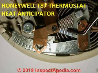
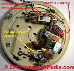
Our page top photo illustrates key parts of a traditional room thermostat including the temperature sensing device, thermostat switch, and the heat anticipator assembly.
InspectAPedia tolerates no conflicts of interest. We have no relationship with advertisers, products, or services discussed at this website.
- Daniel Friedman, Publisher/Editor/Author - See WHO ARE WE?
What is a Thermostat Heat Anticipator & How Does it Work?
 BOTTOM LINE on Room Thermostat HEAT ANTICIPATORS
For most readers the important thing to understand is that IF your thermostat has a heat anticipator, you can actually leave it alone, but your thermostat might work slightly better, avoiding heating "overshoot" on a call for heat, by setting the anticipator to turn off heat slightly early.
A heat anticipator is a very tiny electric heater inside of some room thermostats.
By providing a tiny bit of extra heat inside the thermostat itself, the "anticipator" fools the thermostat into thinking that the room has reached the set temperature on the thermostat a little before the room has actually done-so, causing the thermostat to shut off the boiler slightly "early".
The reason for that feature is that some heating systems such as large cast iron radiators, have so much thermal mass that they continue to radiate a lot of heat even after the thermostat has been satisfied and has turned off the boiler.
The result can be temperature "overshoot" in which the room gets a bit warmer than occupants want.
Details about this little device, how it works, and how it is adjusted are given below.
What's a Heat Anticipator?
Many room thermostats use a flat bi-metallic spring shaped into a coil that responds to changes in room temperature by moving a mercury switch (older units) that turns the buildings heating system on and off.
A heat anticipator, found inside some room thermostats, and usually near the bimetallic spring is itself a tiny electric heater - a wire that gets warm.
Depending on its setting, the heat anticipator warms up the bi-metallic spring enough to turn the actual heating system OFF a bit early - before the room has actually reached the set-temperature on the wall thermostat.
Hence it's name "heat anticipator" - you might say it's "anticipating" the heat rise that will continue occur in the room after the heating system has actually turned off.
Because many people find this concept a bit confusing, the rest of this article explains in more detail how the heat anticipator works and gives a bit of its history.
For readers who need to know just how to set the heat anticipator on their thermostat, you can skip the details below and go directly
to HEAT ANTICIPATOR ADJUSTMENT.
A heat anticipator is used to avoid room temperature overshoot
Heating technicians call this room over-heating problem room temperature overshoot.
Stopping the call for heat a little early allows for the delivery of residual heat that is already in the boiler or furnace but that has not yet reached the living space.
[Click to enlarge any image]
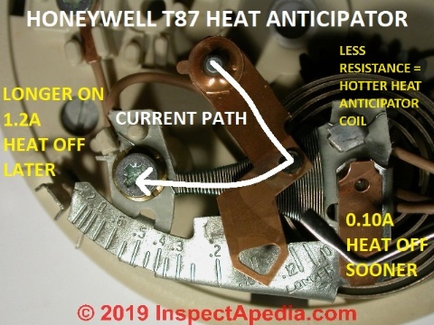
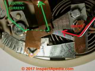
In my photo above the green arrow and dots show the path of electricity through the heat anticipator.
How a Heat Anticipator Produces Its Own Heat
Current flows through a tan wire to the heat anticipator's mounting screw at the left side of the photo, from there through the flat-coiled nichrome wire, up through the black contact button on the movable adjuster, through the adjuster's copper arm, and back into the thermostat.
The green dots show the electrical current's path through the small left end of the heater that is mostly hidden by copper pointer.
The red arrow, which I regret as it clutters the photos, is a pointer to the wider portion of the body of the nichrome wire heating element. Notice that the little nichrome wire heater is located conveniently just above the coiled bi-metallic spring that turns the thermostat's control wire on and off to turn the heating system on and off.
A Nano-Sized History of the Thermostat Heat Anticipator
The first heat anticipator was produced in 1924 (Walker 2008 cited atReferences or Citations ) in a design that, like the heat anticipator described in Honeywell's T87, used the heat output of an electric current passing through a tiny heating device (a coil of nichrome wire) to warm the coiled bimetallic spring that in turn was used to turn off the thermostat ahead of the time when the room would reach the set temperature called for on the thermostat control.
This was an improvement to a much-older device, the electric room thermostat patented in 1883 the U.S. by Warren Johnson (Johnson Controls).
Just two years later in 1885 Albert Butz patented a furnace heat output regulator that used a moving flap to adjust air entry into a heating furnace.
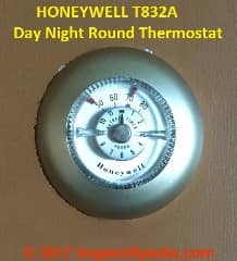
Butz's company, The Electric Heat Regulator Company ultimately became the Honeywell Corporation whose 1960 first round wall thermostat is shown above. This classic 1960 Honeywell T8332A round day-night thermostat is illustrated and discussed further
More details follow below.
A heat anticipator is actually a tiny electric heater inside of the room thermostat
 The heat anticipator, not found on all thermostats, is a tiny little electric heater that will, depending on its setting, warm up the inside of the thermostat, thus warming the thermostat's room temperature sensor, thus fooling the thermostat into thinking the room is a little warmer than it actually is.
That little heat anticipating joke played on the thermostat's room temperature sensor causes it to "open" its contacts (stop calling for heat) a little before the room temperature actually reaches the thermostat's "set" temperature.
The heat anticipator is anticipating the additional heat that is going to arrive and regulating the thermostat accordingly.
Thus we avoid overshooting: we avoid making the room warmer than the thermostat's set temperature.
You won't find a heat anticipator in all thermostats. In fact most newer room thermostats use a thermistor to sense room temperature and they do not usually include a heat anticipator device.
In our photograph above you can see the critical components of a thermostat heat anticipator such as in the Honeywell T87.
Details of how a heat anticipator works inside of a wall thermostat
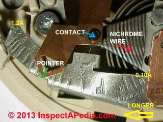
The components of the heat anticipator are shown in the photo and are explained in more detail below. They include:
- A scale showing Amperes or current ranging from 1.2 at the left to 0.10 at the right end of the scale.
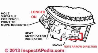
Watch out: The location of the word "LONGER" at the right end of the Amps scale on some but not all Honeywell thermostats may be confusing
The scale includes the word LONGER imprinted at its right end where we see the lowest amps numbers.
Honeywell, a company I admire, ought nonetheless to apologize to everyone for the countless hours of confusion caused by this unfortunate detail.
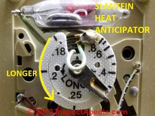
If you click to enlarge the photo you'll see an arrow below the word LONGER that points to the left, to the larger Amps numbers at the other end of the scale.
What is meant by the word "LONGER" is that for a given system, moving the lever to the left as indicated by the arrow, will result in longer cycles (lower Cycles Per Hour - CPH).
This is due to less anticipation heat being generated when moving the lever to the left. If the system current is measured when setting up a system, setting the lever to that current will result in close to 6 CPH when at 50% system load. For loads less than 50% or greater than 50% the cycling rate will be slower. - A brass pointer indicating the heat anticipator setting along the Amps scale.
- A resistance heating wire, probably nichrome wire, wound around a triangular base.
- An electrical contact that slides to different positions on the resistance wire coil.
The Nichrome Wire in the Heat Anticipator is a Tiny Electric Heater
The heat anticipator in an electromechanical thermostat includes a tiny heating coil of nichrome wire which gets warm as electricity (current) flows through the wire.
Moving the pointer along the Amps scale moves the position of the contact that in turn changes the length of nichrome wire that will be used, making the in-use wire shorter or longer.
Meaning of the Numbers on the Heat Anticipator Scale
The heat anticipator numbers along its scale, typically from 0.10A to 1.2A are measurements of current or Amps that will flow through the heat anticipator's little heater at different settings.
At ELECTRICAL RESISTANCE vs HEAT GENERATED we explain that when the electrical resistance of a circuit is higher less current flows and less heat is generated.
When we move the heat anticipator adjusting arm we are moving an electrical contact (blue arrow) along the flat-wound resistor wire, effectively increasing (to the higher current numbers on the left) or decreasing (to the lower current numbers on the right) the amps or current flow through this tiny heating device by lengthening or shortening the total length of wire included in the heater circuit.
Increasing or decreasing the wire length included in the circuit changes how hot the wire gets as current flows through it.
Above: the heat anticipator pointer is set to about 0.45 Amps.
Longest Heat-on Cycle
For the heat anticipator above, when we move the arm and contact fully to the left to the 1.2A (longest-on position) we will see the least current flow, least in-thermostat-heating, so we turn the actual heating system off later.
Thus the highest (1.2A) position gives the longest heat-on cycle. (Jaffe 1997)
Some thermostats like the SlantFin thermostat shown below (actually made by Honeywell for SlantFin) range between 0.18A and 0.8A - the 0.8A setting gives the longest heat-on cycle for this thermostat.
Really? Well not in all thermostat designs: there may be some thermostat heat anticipator designs that use a longer or shorter nichrome wire to provide more or less heat respectively by keeping the current flow (amps) uniform - in such a design the longer heater wire would put out more heat and would give a shorter heating system on-cycle.
Shortest Heat-On Cycle
If we move the arm and contact fully to the right to the 0.1A position we will see the highest current flow through the wire, so the wire gets hotter, so it produces the most in-thermostat-heating, so the thermostat inside warms up faster than the room air, so the thermostat will turn off the actual heating system off sooner.
Thus the 0.1A position gives the shortest heat-on cycle in thermostat heat anticipators of this design.
Watch out: in general Honeywell warns to never set the T87F series heat anticipator below 0.3A. Specifications and settings for other heat anticipator thermostat brands and models will vary.
How & Why Adjusting the Heat Anticipator Changes Its Heat Output - Variable Resistor
 That tiny resistance wire or on older thermostats, a wire wound into a flat coil, is a tiny electrical resistance heater that puts some heat into the interior of the thermostat, fooling it into thinking the room is just a little warmer than it is.
The heating thermostat manufacturer's instructions & heat anticipator operation explanation can be a bit confusing, but significantly, as we detail
at HEAT ANTICIPATOR ADJUSTMENT
The shortest burner-on time will be when the heat anticipator puts out the most heat. This warms up the thermostat's room temperature sensor and therefore tells the thermostat the room is up to set temperature earliest.
The longest burner-on time will be when the heat anticipator puts out the least heat, thus does not turn off heat early, thus lets the burner keep running longer.
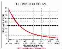
The graph at above left, adapted from one provided by Carrier, illustrates how a different device, a thermistor, translates temperature changes into a change in electrical resistance that in turn can be used by a room thermostat to control building heating equipment. That's how newer thermostats work.
Details of those devices used in many modern heating and cooling thermostats are found
at THERMISTORS
Changing the Heat Anticipator's Pointer Changes the Wire Length, Current Amps, Heat Output
 More heat output from our teensy electrical resistance heater inside the wall thermostat means more room heat anticipation (more pre-heating of the room thermostat's sensor) and thus a shorter heat-on cycle.
Here we explain heat anticipators a second time to offer another way to understand what's happening in a thermostat that uses a heat anticipator circuit.
Moving the heat anticipator pointer (the open triangle at the top of the copper arm) changes the effective wire length and thus the electrical resistance and thus the heat output of the heat anticipator inside the thermostat.
When we move the adjuster we are essentially using more (longer) or less (shorter) lengths of wire, thus causing more or less resistance through the device.
Key Concepts: Relationship of Wire Length, Resistance (Ohms), Current flow (Amps), Heat Generated, Heat Anticipator Warming, Heating System On-Cycle
If we assume, as is the case for a typical heating system thermostat, that the thermostat voltage level remains fixed (typically 24VAC) then moving the heat anticipator position changes the length of the nichrome wire in the active circuit.
Longer Wire = More electrical resistance = less current flow = less heat generated by the heat anticipator = less pre-warming of the thermostat = longer heat on cycle.
Shorter Wire = Less electrical resistance = more current flow = more heat generated by the heat anticipator = more pre-warming of the thermostat's sensor = shorter burner on time
Below: the heat anticipator pointer has been moved down towards the right end of the scale, and is set to about 0.15 Amps.
- LONGER Heat-ON Cycles: if the heating system shuts off before the thermostat set temperature is reached, move the heat anticipator up to a higher number by 0.1A - this will reduce the heat anticipator output and will keep the heating system on longer.
- SHORTER Heat-ON Cycles: If the heating system stays on too long, move the heat anticipator down to a lower number by 0.1A - this will turn the heating system off sooner by telling the heat anticipator to anticipate or pre-warm the thermostat sensor.
Shorter Wire = Less electrical resistance = more current flows, more heat is generated by the heat anticipator = more pre-warming of the thermostat's sensor = shorter burner on time.
Watch out: before changing the heat anticipator setting you might want to read both the manufacturer's actual recommended settings and our explanation about matching the heat anticipator to the actual installed-thermostat circuit's current draw in the rest of this article.
Really? Many of us have found the heat anticipator in thermostats confusing because we think intuitively but incorrectly that more resistance means more heat is generated. No.
That's wrong.
More resistance (higher Amps numbers) = less current flow = less heat is generated = the heat anticipator heats up less = the thermostat turns off the heat later (or it runs "longer").
A heat anticipator will not work accurately unless the following conditions are met:
- The heating or air conditioning system itself has been adjusted to match the electrical current of the valve or relay which the thermostat is controlling. This is a technical problem for your heating or air conditioning service technician, not something a homeowner can address.
- The thermostat is installed at a location where voltage and current (amps) fall on or within the limits of the adjustable heat anticipator
- The thermostat is not installed on a power pile system (don't ask).
- The heat anticipator on the thermostat should be set to match the requirement & electrical characteristics of the particular heating or air conditioning control circuit that it is switching on and off.
Useful References for Thermostat Heat Anticipators
- Honeywell CT87A,B,J Round® Thermostat Low Voltage (15 to 30 VAC) Thermostat and Mounting Hardware Installation Instructions (2002) [PDF]
- Honeywell T87F Thermostat PRODUCT DATA SHEET & CIRCUIT DIAGRAMS [PDF] (2002)
- Honeywell CT87A,B,J Round® Thermostat Low Voltage (15 to 30 VAC) Thermostat and Mounting Hardware Installation Instructions [PDF], Honeywell International Inc. Honeywell Limited—Honeywell Limitée 1985 Douglas Drive North 35 Dynamic Drive Golden Valley, MN 55422 Scarborough, Ontario M1V 4Z9, 60-0830—4 G.H. Rev. 8-02, retrieved 12/1/2013 Website: www.honeywell.com
- Jaffe, James S, THERMOSTAT HEATERS [PDF], Fueloil & Oil Heat with Air Conditioning, February 1997
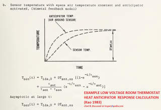
- Kao, James Y., George Sushinsky, David A. Didon, A.J. Matascusa, & Joseph Chi, LOW VOLTAGE ROOM THERMOSTAT PERFORMANCE [PDF] (1983) U.S. Department of Commerce & U.S. National Bureau of Standards, retrieved 2021/02/07 original source: nvlpubs.nist.gov/nistpubs/Legacy/BSS/nbsbuildingscience150.pdf
- T.D. Instruments Corporation, The MINI AMMETER used for adjusting thermostats to work precisely was produced by and may still be available from T.D. Instruments Corporation, 180 Charlotte St., Rochester, NY 14067 - 716-232-4208. We used model T.D. 2, which operates between 0 and 1.2 Amps A.C. If this instrument is not available look for an ammeter capable of operating with precision in the same very low-end range of current draw from 0 - 2 Amps.
- White Rodgers Thermostats and HVAC controls,
Homeowner information: http://www.emersonclimate.com/en-US/brands/white_rodgers/Pages/wr-homeowner-info.aspx
Contractor information: http://www.emersonclimate.com/en-US/brands/white_rodgers/wr_contractor_info/Pages/white-rodgers-contractor-info.aspx
White Rodgers Product Catalog (don't misspell the company's name as White Rogers Thermostats) - http://www.emersonclimate.com/Documents/thermostats.pdf - Thermostat Catalog - Domestic Central Heating Wiring Systems and Controls, [book at amazon] 2d Ed., Raymond Ward, Newnes, ISBN-10: 0750664363, ISBN-13: 978-0750664363, Quoting from Amazon.com:
- "Automatic Oil Burner Controls - Thermostats", Domestic and Commercial Oil Burners, [book at Amazon] 3rd Ed., Charles H. Burkhardt, McGraw Hill, 1969 (and later editions), ASIN B0000EG4Y8
- More reference sources are found at the end of this page atReferences or Citations
Why Lower Electrical Resistance Means More Heat is Generated and Why Higher Electrical Resistance Means Less Heat is Generated in a Heat Anticipator Circuit
Details about the relationship between electrical resistance and heat are at ELECTRICAL RESISTANCE vs HEAT GENERATED.
What is the Difference Between the Heat Anticipator and an Aquastat Heating Control Differential?
The differential is the temperature (or pressure) change or "differential" between the LOW and HIGH settings of a heating system control.
See AQUASTAT CONTROL FUNCTIONS for an example of control differential settings on heating equipment.
...
Reader Comments, Questions & Answers About The Article Above
Below you will find questions and answers previously posted on this page at its page bottom reader comment box.
Reader Q&A - also see RECOMMENDED ARTICLES & FAQs
On 2021-02-07 by anonymous - I knew the engineer who put "LONGER" on the heat anticipator. It is in the correct direction.
I knew the engineer who put longer on that part. It is in the correct direction. As some have pointed out above the anticipation resistance in small compared to the total resistance in the system. Thus the system has nearly constant current when in the on cycle independent on anticipator setting. Why does this make longer point to the left?
Assume the anticipator is set to the farthest right of the scale. This will provide the maximum anticipator heat and shortest cycles for the system. If moved to the left, the resistance will be less as the wire is shorter. The current stays the same therefore the anticipator heat is reduced. Reduced anticipator heat will cause the system to cycle slower therefore longer cycles.
There is a subtle thing that happens when the anticipator contact passes the little twisted tap. Part of the anticipator is in parallel with the bimetal of the thermostat. Part of the current goes through the bimetal when the anticipator is to the right of the tap.
The current in the bimetal produces direct heating of the bimetal. Moving left of the tap less current flows through the bimetal and more current flows through the anticipator but at reduced resistance. This again lowers the anticipator heat.
Many mechanical thermostats are designed to cycle around 6 cycles per hour at a 50% load. The markings are determined by testing at various current levels using a NEMA test chamber as described in:
https://nvlpubs.nist.gov/nistpubs/Legacy/BSS/nbsbuildingscience150.pdf.
This article also delves in to the math behind anticipation.
On 2021-02-07 by (mod)
Thank you very much, Anon for the helpful comment and for that NIST government publication - it's a great find and not one I had in our library; I'll add it for ease of location by other readers;
Kao, James Y., George Sushinsky, David A. Didon, A.J. Matascusa, & Joseph Chi, LOW VOLTAGE ROOM THERMOSTAT PERFORMANCE [PDF] (1983) U.S. Department of Commerce & U.S. National Bureau of Standards, retrieved 2021/02/07 original source: https://nvlpubs.nist.gov/nistpubs/Legacy/BSS/nbsbuildingscience150.pdf
On 2020-09-21 - by William O. - typical resistance across the entire length of an anticipator heater in a thermostat?
RE-posting:
William O. said:
What is a typical resistance across the entire length of an anticipator heater in a thermostat?
This Q&A were posted originally
at ELECTRICAL RESISTANCE vs HEAT GENERATED
Moderator reply:
William
Thanks for a helpful question on the resistance of HVAC thermostat heat anticipators.
Please see details at HEAT ANTICIPATOR OPERATION
where we note that the range of adjustment of a typical Honeywell heat anticipator was between 1.2A and 0.10A.
The current powering most heating system thermostats is 24VAC.
Resistance in Ohms R (Ω) = Volts ÷ Amps or V/I or about 20 ohms.
On 2020-09-23 by William O.
Thanks! I asked because a lot in this article didn’t make sense to me.
I found my answer in the
HEAT ANTICIPATOR ADJUSTMENT - T87 article. [Discusses Ohm's Law - Ed.]
“The anticipator resistance is much lower than the resistance of the gas valve coil [or the circulator relay coil]. That means that no matter where the anticipator is adjusted, it does not appreciably affect the current in the circuit. In other words, the current through the anticipator is constant for your furnace [or hot water boiler or steam boiler], no matter where the anticipator is adjusted.”
So we want the voltage drop across the thermostat to be quite small perhaps 2-volts at most.
On 2020-09-23 - by (mod) -
Thanks, William;
Prompted by your comment, I recall coming across that and inserting it into the text.
Keep in mind that voltage drop is not the same number as electrical resistance - though they're related.
On 2019-02-14 by Anonymous - more resistance is more heat from the anticipator, because the current is basically constant
no, more resistance is more heat from the anticipator, because the current is basically constant (moderated by the resistance of the relays and solenoids at the other end of the wire.
On 2019-04-14 - by (mod) -
This old heating article will be of interest
Jaffe, James S, THERMOSTAT HEATERS [PDF], Fueloil & Oil Heat with Air Conditioning, February 1997
at inspectapedia.com/heat/Thermostat-heaters-Jaffe.pdf
The schematic below is from a current T87F Family product data sheet from Honeywell, cited in these articles
IMAGE LOST by older version of Clark Van Oyen’s useful Comments code - now fixed. Please re-post the image if you can. Sorry. Mod.
On 2017-10-18 by Davetonk - tested my thermostat by blowing on it with a hair dryer
I used a hair dryer to heat my Honeywell T-87 type room thermostat to see if it would shut down my Crown boiler. That worked as a test but now I wonder if that could dammage the anticipator.
On 2017-10-18 - by (mod) -
Dave: possibly if you subjected the thermostat to very high temperature. You'll know if by turning up the thermostat to above the current room temperature that fails to turn on your heating system - an easier test than the hair dryer approach.
On 2017-05-16 by Jenn - thermostat is OFF but I'm still getting heat
I turned my thermostat off but heat is still felt on my heaters I live in a building any suggestions
On 2017-05-16 - by (mod) -
Sure, Jenn,
Please see
HEAT WON'T TURN OFF
And you'll find a sequence of Diagnostic and repair suggestions for just this problem. Please take a look and let me know if you have further questions and I'll be glad to work directly with you on this
Daniel
...
Continue reading at HEAT ANTICIPATOR ADJUSTMENT or select a topic from the closely-related articles below, or see the complete ARTICLE INDEX.
Or see these
Recommended Articles
- AMPS MEASUREMENT AUTOMOTIVE DC
- AMPS MEASUREMENT METHODS
- BOILER CONTROLS & SWITCHES
- DEFINITION OF AMPS, ELECTRICAL CURRENT
- DEFINITION OF OHMS, ELECTRICAL RESISTANCE
- ELECTRICAL RESISTANCE vs HEAT GENERATED
- FURNACE CONTROLS & SWITCHES
- HEAT ANTICIPATOR ADJUSTMENT
- HEAT ANTICIPATOR ADJUSTMENT - T87 - and the role of Ohm's Law (resistance)
- HEAT ANTICIPATOR EFFECTS on ROOM TEMPERATURE
- HEAT ANTICIPATOR OPERATION
- HEAT ANTICIPATOR SET & TEST by AMMETER
- HEAT ANTICIPATOR THERMOSTAT SOURCES
- HEAT WON'T TURN OFF
- STEAM HEATING SYSTEMS
- TEMPERATURE RESPONSE of ROOM THERMOSTATS
- THERMOSTAT WIRE CONNECTIONS
- VOLTS / AMPS MEASUREMENT EQUIP
Suggested citation for this web page
HEAT ANTICIPATOR OPERATION at InspectApedia.com - online encyclopedia of building & environmental inspection, testing, diagnosis, repair, & problem prevention advice.
Or see this
INDEX to RELATED ARTICLES: ARTICLE INDEX to HVAC THERMOSTATS
Or use the SEARCH BOX found below to Ask a Question or Search InspectApedia
Ask a Question or Search InspectApedia
Try the search box just below, or if you prefer, post a question or comment in the Comments box below and we will respond promptly.
Search the InspectApedia website
Note: appearance of your Comment below may be delayed: if your comment contains an image, photograph, web link, or text that looks to the software as if it might be a web link, your posting will appear after it has been approved by a moderator. Apologies for the delay.
Only one image can be added per comment but you can post as many comments, and therefore images, as you like.
You will not receive a notification when a response to your question has been posted.
Please bookmark this page to make it easy for you to check back for our response.
IF above you see "Comment Form is loading comments..." then COMMENT BOX - countable.ca / bawkbox.com IS NOT WORKING.
In any case you are welcome to send an email directly to us at InspectApedia.com at editor@inspectApedia.com
We'll reply to you directly. Please help us help you by noting, in your email, the URL of the InspectApedia page where you wanted to comment.
Citations & References
In addition to any citations in the article above, a full list is available on request.
- Walker, Iain S., and Alan K. Meier. RESIDENTIAL THERMOSTATS: COMFORT CONTROLS IN CALIFORNIA HOMES [PDF] Lawrence Berkeley National Laboratory 7 (2008).
Abstract: This report summarizes results of a literature review, a workshop, and many meetings with demand response and thermostat researchers and implementers. The information obtained from these resources was used to identify key issues of thermostat performance from both energy savings and peak demand perspectives. A research plan was developed to address these issues and activities have already begun to pursue the research agenda. - [1] Proliphix Corporate Headquarters [Website: proliphix.com] , 3 LAN Drive Suite #100, Westford, MA 01886 Phone: +1.978.692.3375 Toll Free (U.S.): 866-IP-LIVING (866.475.4846) Fax: +1.978.692.3378 - Sales: sales@proliphix.com Marketing: marketing@proliphix.com Customer support: support@proliphix.com http://www.proliphix.com/ - quoting from the company's website:
All Proliphix Network Thermostats come with our free Uniphy Remote Management Service. This unique offering lets you monitor and control your HVAC systems by simply pointing your Browser to our secure Proliphix Web Site. Enjoy the convenience of programming a thermostat from any location, using a simple graphical interface. No computer equipment or software is required. And since Proliphix takes care of the network configuration for you, you’ll be up and running in no time. We’ll even proactively monitor your thermostats and send you an immediate email or SMS message when an HVAC problem is detected. - [2] "The Nest Learning Thermostat", Nest Thermostat, 900 Hansen Way Palo Alto, CA 94304, Tel: 855-4MY-NEST, Email: info@nest.com, website http://www.nest.com/, retrieved 1/24/2013.
- [3] Honeywell Controls, the company wants you to use their contact form at this web page: http://www51.honeywell.com/honeywell/contact-support/contact-us.html
Honeywell Consumer Products, 39 Old Ridgebury Road Danbury, CT 06810-5110 - (203) 830-7800
World Headquarters, Honeywell International Inc., 101 Columbia Road, Morristown, NJ 07962, Phone: (973) 455-2000, Fax: (973) 455-4807 1-800-328-5111 - [3a] Honeywell Tradeline T87T Universal Thermostat Installation Instructions for the Trained Service Technician", Honeywell International Inc. Honeywell Limited—Honeywell Limitée 1985 Douglas Drive North 35 Dynamic Drive Golden Valley, MN 55422 Scarborough, Ontario M1V 4Z9, 60-0830—4 G.H. Rev. 8-02, retrieved 12/1/2013 Website: www.honeywell.com
- [7] Fuel Oil & Oil Heating Magazine, 3621 Hill Rd., Parsippany, NJ 07054, 973-331-9545
- [8] Domestic and Commercial Oil Burners, Charles H. Burkhardt, McGraw Hill Book Company, New York 3rd Ed 1969.
- [9] National Fuel Gas Code (Z223.1) $16.00 and National Fuel Gas Code Handbook (Z223.2) $47.00 American Gas Association (A.G.A.), 1515 Wilson Boulevard, Arlington, VA 22209 also available from National Fire Protection Association, Batterymarch Park, Quincy, MA 02269. Fundamentals of Gas Appliance Venting and Ventilation, 1985, American Gas Association Laboratories, Engineering Services Department. American Gas Association, 1515 Wilson Boulevard, Arlington, VA 22209. Catalog #XHO585. Reprinted 1989.
- [10] The Steam Book, 1984, Training and Education Department, Fluid Handling Division, ITT [probably out of print, possibly available from several home inspection supply companies] Fuel Oil and Oil Heat Magazine, October 1990, offers an update,
- [11] Principles of Steam Heating, $13.25 includes postage. Fuel oil & Oil Heat Magazine, 389 Passaic Ave., Fairfield, NJ 07004.
- [12] The Lost Art of Steam Heating, Dan Holohan, 516-579-3046 FAX
- Principles of Steam Heating, Dan Holohan, technical editor of Fuel Oil and Oil Heat magazine, 389 Passaic Ave., Fairfield, NJ 07004 ($12.+1.25 postage/handling).
- [13] "Residential Steam Heating Systems", Instructional Technologies Institute, Inc., 145 "D" Grassy Plain St., Bethel, CT 06801 800/227-1663 [home inspection training material] 1987
- [14] "Residential Hydronic (circulating hot water) Heating Systems", Instructional Technologies Institute, Inc., 145 "D" Grassy Plain St., Bethel, CT 06801 800/227-1663 [home inspection training material] 1987
- [15] "Warm Air Heating Systems". Instructional Technologies Institute, Inc., 145 "D" Grassy Plain St., Bethel, CT 06801 800/227-1663 [home inspection training material] 1987
- [16] Heating, Ventilating, and Air Conditioning Volume I, Heating Fundamentals,
- [17] Boilers, Boiler Conversions, James E. Brumbaugh, ISBN 0-672-23389-4 (v. 1) Volume II, Oil, Gas, and Coal Burners, Controls, Ducts, Piping, Valves, James E. Brumbaugh, ISBN 0-672-23390-7 (v. 2) Volume III, Radiant Heating, Water Heaters, Ventilation, Air Conditioning, Heat Pumps, Air Cleaners, James E. Brumbaugh, ISBN 0-672-23383-5 (v. 3) or ISBN 0-672-23380-0 (set) Special Sales Director, Macmillan Publishing Co., 866 Third Ave., New York, NY 10022. Macmillan Publishing Co., NY
- [18] Installation Guide for Residential Hydronic Heating Systems
- [19] Installation Guide #200, The Hydronics Institute, 35 Russo Place, Berkeley Heights, NJ 07922
- [20] The ABC's of Retention Head Oil Burners, National Association of Oil Heat Service Managers, TM 115, National Old Timers' Association of the Energy Industry, PO Box 168, Mineola, NY 11501. (Excellent tips on spotting problems on oil-fired heating equipment. Booklet.)
- [21] Trane TCONT800 Series Touch Screen Programmable Comfort Control Ownes Guide, American Standard, Inc., Troup Highway, Tyler TX 75711, January 2005, Telephone: Customer Service: 1-877-3381, website: www.trane.com
- [22] ...
- [23] RTI Electronics. "NTC Thermistor Product Guide", 1999, RTI Electronics, Inc., 1800 E. Via Burton St., Anaheim CA 92806, Tel: 714-630-0081
- Our recommended books about building & mechanical systems design, inspection, problem diagnosis, and repair, and about indoor environment and IAQ testing, diagnosis, and cleanup are at the InspectAPedia Bookstore. Also see our Book Reviews - InspectAPedia.
- In addition to citations & references found in this article, see the research citations given at the end of the related articles found at our suggested
CONTINUE READING or RECOMMENDED ARTICLES.
- Carson, Dunlop & Associates Ltd., 120 Carlton Street Suite 407, Toronto ON M5A 4K2. Tel: (416) 964-9415 1-800-268-7070 Email: info@carsondunlop.com. Alan Carson is a past president of ASHI, the American Society of Home Inspectors.
Thanks to Alan Carson and Bob Dunlop, for permission for InspectAPedia to use text excerpts from The HOME REFERENCE BOOK - the Encyclopedia of Homes and to use illustrations from The ILLUSTRATED HOME .
Carson Dunlop Associates provides extensive home inspection education and report writing material. In gratitude we provide links to tsome Carson Dunlop Associates products and services.


