
 Joules Heating Law
Definition of Resistive Heating, Ohmic Heating

- POST a QUESTION or COMMENT about thermostat heat anticipator circuits & controls.
What is Joules Heating Law.
This article defines Joules Heating Law and explains how and why resistive heating or ohmic heating occurs in electrical circuits, appliances, or lights.
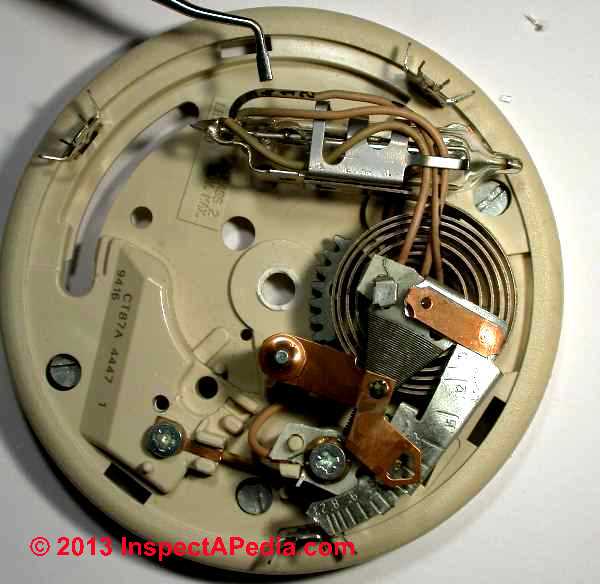
We use an older Honeywell T87 type thermostat heat anticipator device to explain the relationship between electrical resistance and heat generated by a wire when current flows through it.
Our page top photo illustrates key parts of a traditional
InspectAPedia tolerates no conflicts of interest. We have no relationship with advertisers, products, or services discussed at this website.
- Daniel Friedman, Publisher/Editor/Author - See WHO ARE WE?
Jules Heating Law, Resistive Heating, Ohmic Heating Explained
 Joules Law Describes Joule Heating or ohmic heating or resistive heating.
Definition: Joule Heating is a synonym for resistive heating or ohmic heating: forms of heat generated when an electric current flows through a resistant path thus losing energy that is in turn given off as heat.
Joule heating can also be described at a more microscopic level:
In the flow of electricity electrons move through the electrical path whose conductivity is limited.
As flowing electrons smack into atoms that comprise the molecules of the conductor (for example the atoms of the molecules of a nichrome heater wire), the electron's energy is transferred into the conductor's molecules in the form of heat.
In this article we use the teensy wound nichrome wire heater of a Honeywell T87 room thermostat heat anticipator as our example resistive Joules-heating device.
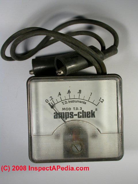
The mini amps checker shown in our photo is used to test the current flow through a room thermostat in order to set the heat anticipator correctly.
[Click to enlarge any image]
Formula for Joules Law
The movement of electrical current through a wire produces heat. The amount of heat that will be produced when electrical current flows through a conductor is described as
Joules Law: H = I2 x R x T
where H = heat, I = current in Amps, R= resistance in Ohms, T is duration of current flow in seconds.
The T or time factor is necessary when we are dealing with alternating current.
In a DC circuit we can forget T.
More resistance means that more heat is generated
Joules Law says that the amount of heat (H) generated when current flows through a wire is the product of the square of the current I2 times the resistance of the wire R to which we can add a factor for time T
If we increase the resistance we increase the amount of heat generated.
If we increase the time (over which the circuit is active) we also increase the total amount of heat generated.
It's a bit simplistic, but if I've got this right, as the atoms in a wire resist the flow of electrons heat is generated as a result of collisions and thus the production of kinetic energy. [Really?]
Think of two nice examples, light bulb filaments in incandescent bulbs and the wire element in an electrical fuse. Eventually the heat is enough to light the filament or melt the fuse wire, opening the circuit.
This is opposite of what some readers cited. They explained that at higher resistance less current flowed so less heat was generated.
 They are right too. Why?
How to calculate the heat output of an electrical-resistance wire
The heat output of an electrical-resistance wire is a function of the supply voltage and the heater resistance (Watts = Voltage2 / Resistance).
Lower resistance produces more heat.
(Paraphrasing from a nice article on electrical resistance heating provided by process technology dot com)
Since in our heat anticipator voltage is constant (say 24V), all we can vary is resistance (moving the slider) where watts (which we can call a measure of heat output) will drop when resistance is increased.
I think part of the trouble we got into was confusion of electrical power with heat. These excerpts are from physicsforums.com
Let's assume that the voltage is constant, say 12V. ... if the resistance was 1 Ohm, ... the current would be 12A. ... the total power would be 144W.
If the resistance was 12 Ohms, ... the current would be 1A, ... the total power is 12W. ... lower resistance would emit more heat.
to which another reader replied:
P= VI but that is NOT the heat. ... heat is energy, not power.
The heat a resistor produces is the energy loss given by I2 R.
If you assume a fixed voltage and resistance, then
I= V/R so the heat produced is given by
(V/R)2(R) = V2 / R.
Look at the math. Lower resistance will produce more heat because more current flows.
It's fair to be confused. In the same forum a subsequent reader explains why house wiring under normal loads would not overheat.
In the Heating element example you are assuming that the wire is the only resistance in the circuit and therefore all the voltage is felt across it. With house wiring, the wire delivers electricity to a load that has a much greater resistance than the wires. Therefore the vast majority of the voltage is dropped across the load, and very little across the wires.
The lower the resistance of the wires, the smaller the voltage dropped by them, and the less heating they experience for any given load.
Now if you change resistances, the following happens.
If you use a very large resistance for the element, it drops the majority of the voltage, but limits the current and you get little heating in the element.
If you use a very small resistance, most of the voltage is dropped across the internal resistance of the battery, and you get little voltage across the element and you get little heating.
If you plot the heat (wattage usage) of the element vs the resistance of the element, you will find that the maximum [heating] occurs when the Element's resistance equals that of the internal resistance of the source.
From the same source another reader [we corrected the physicist's spelling] points out the relationship between electrical resistance and wire length.
This is key in understanding how the Honeywell thermostat's heat anticipator adjustment works since sliding the adjuster towards the maximum resistance end (1.2A) is using the full length of coiled wire while sliding the little adjuster towards the minimum resistance end (0.1A) uses the shortest length of wire.
Consider two equal diameter wires with the same resistance but of different materials, say copper and nichrome, since the resistivity of copper is something like 50 times less then that of nichrome the copper wire will be much longer then the nichrome.
Now each is the same resistance so each will suffer the same I2R loss, but since the copper wire is ~50 times the length of the nichrome wire it will be able to dissipate 50 times the heat at any given temperature (this is assuming equal emissitivity).
Which wire will be hotter? The shorter nichrome wire of course. So you need to look at more then just the resistance to evaluate the temperature of a conducting wire.
and finally from yet another commentator:
... the greater the resistance the more likely collisions will occur with the charge flow transferring some of the kinetic energy from an electron and generating heat in the process, but far less often because the amount of charge that is flowing is perhaps half of what it was.
When the resistance is decreased, more charges can flow per unit time and therefore transfer more energy into the resistance than before.
It is less likely that collisions will occur with a lower resistance for the same charge flowing through it, but given the greater amount of charges that make it through the lower resistance, the collisions that do occur happen more often because there are so many more of them.
In colliding with the resistive material they transfer some of their kinetic energy into heat within the resistance.
... the reason a lower resistance takes more energy from the source per unit time (power) is because more charge is allowed to flow when the resistance is lowered therefore transferring more energy from the source to the resistive load ... - retrieved 17 June 2015 original source: Physics Forum, www.physicsforums.com/threads/resistance-of-a-heating-element.5608/
Calculation Example: Why a Wire with Less Resistance Generates More Heat
Really? Why does a wire with less resistance (Ohms), for example a shorter wire, pass more current (Amps) and why does this less-resistant wire generate more heat than the longer, higher resistant wire?
At DEFINITION of ELECTRICAL RESISTANCE, OHM's LAW we give Georg Ohm's Law,
I = V / R
That formula tells us that the I or current (Amps) through a conductor (wire) between two points on a circuit is inversely proportional to R the resistance between them (ohms).
I = the current, measured in Amps; I = V / R
V = the difference in potential between the same two points, measured in Volts; V = I x R
R = the resistance in the conductor or circuit between the same two points, measured in Ohms; R = V / I
Now let's look not just at electrical resistance but at the heat generated when we change the resistance value or R or Ohms.
In this simplified Joules Law: H = I2 x R
notice that the heat output H of the circuit is the square of the current I x the resistance R.
Watch what happens when we lower the resistance in along the heater wire in a heat anticipator:
Case 1: At a fixed voltage V of 24V, at a resistance R of 24 Ohms
I or current will be I = V / R or I = 1 Amp of current flow
The heat output will be heat H = (1)2 x R or (1) x 1 or 1
We don't care about naming the heat units for this example since all I want to do is show how the heat value changes.
Let's drop the resistance from 24 Ohms down to 1 Ohm - maybe by keeping everything else the same but shortening the wire length:
Case 2: At a fixed voltage V, say 24V, at a resistance R of 1 Ohm
I or current will be I = V / R or I = 24 / 1 which gives us 24V Amps of current flow
The heat output will be heat H = (24)2 x R or (576) x 1 or 576 (we don't care about naming the heat units for this example).
Research & References Explaining Joules Heating, Joules Law, Resistive or Ohmic Heating
- Anders, George J. Rating of electric power cables: ampacity computations for transmission, distribution, and industrial applications. IEEE, 1997.
- Aswani, Anil, Neal Master, Jay Taneja, David Culler, and Claire Tomlin. "Reducing transient and steady state electricity consumption in HVAC using learning-based model-predictive control." Proceedings of the IEEE 100, no. 1 (2012): 240-253.
Abstract & Excerpts:
Heating, ventilation, and air conditioning (HVAC) systems are an important target for efficiency improvements through new equipment and retrofitting because of their large energy footprint. One type of equipment that is common in homes and some offices is an electrical, single-stage heat pump air conditioner (AC). To study this setup, we have built the Berkeley Retrofitted and Inexpensive HVAC Testbed for Energy Efficiency (BRITE) platform. ...
. Experiments on BRITE show that our techniques result in a 30%-70% reduction in energy consumption as compared to two-position control, while still maintaining a comfortable room temperature. The energy savings are due to our control scheme compensating for varying occupancy, while considering the transient and steady state electrical consumption of the AC. Our techniques can likely be generalized to other HVAC systems while still maintaining these energy saving features.
... And even though the thermostat in BRITE has a heat anticipator that adjusts the ... - Berryman, James G., and William D. Daily. "Optimal joule heating of the subsurface." U.S. Patent 5,325,918, issued July 5, 1994.
- Buckingham, R. A., and J. Corner. "Tables of second virial and low-pressure Joule-Thomson coefficients for intermolecular potentials with exponential repulsion." In Proceedings of the Royal Society of London A: Mathematical, Physical and Engineering Sciences, vol. 189, no. 1016, pp. 118-129. The Royal Society, 1947.
- Chiu, S. H., T. L. Shao, Chih Chen, D. J. Yao, and C. Y. Hsu. "Infrared microscopy of hot spots induced by Joule heating in flip-chip SnAg solder joints under accelerated electromigration." Applied physics letters 88, no. 2 (2006): 022110.
- Dulzer, Edward, "PTC Electric Immersion Heaters", Smart One Process Technology, Process Technology, 7010 Lindsay Dr., Mentor, OH 44060 U.S.A. Tel: US/CN: 800-621-1998 Website: www.SmartOneHeater.com or www.process-technology.com Email: info@process-technology.com retrieved 17 June 2015, original source http://www.processtechnology.com/pdf/SmartOnearticle.pdf
- El-Tantawy, F., K. Kamada, and H. Ohnabe. "In situ network structure, electrical and thermal properties of conductive epoxy resin–carbon black composites for electrical heater applications." Materials Letters 56, no. 1 (2002): 112-126.
- Hong, Sukjoon, Habeom Lee, Jinhwan Lee, Jinhyeong Kwon, Seungyong Han, Young D. Suh, Hyunmin Cho, Jaeho Shin, Junyeob Yeo, and Seung Hwan Ko. "Highly stretchable and transparent metal nanowire heater for wearable electronics applications." Advanced materials 27, no. 32 (2015): 4744-4751.
Abstract:
A highly stretchable and transparent electrical heater is demonstrated by constructing a partially embedded silver nanowire percolative network on an elastic substrate. The stretchable network heater is applied on human wrists under real-time strain, bending, and twisting, and has potential for lightweight, biocompatible, and versatile wearable applications. - Magnussen, Freddy, and Chandur Sadarangani. "Winding factors and Joule losses of permanent magnet machines with concentrated windings." In Electric Machines and Drives Conference, 2003. IEMDC'03. IEEE International, vol. 1, pp. 333-339. IEEE, 2003.
- Meier, Alan, Cecilia Aragon, Therese Peffer, Marco Pritoni. THERMOSTAT INTERFACE AND USABILITY: A SURVEY [PDF] Lawrence Berkeley National Laboratory, Environmental Energy Technologies Division September 2010, (2011).
Abstract excerpt:
Thermostats have controlled heating and cooling systems in homes for over sixty years. The home thermostat translates occupants' temperature preferences into system operation and displays system conditions for occupants. In this position of an intermediary, the millions of residential thermostats control a huge amount of fuel and electricity consumption
. In the United States, for example, residential thermostats control approximately 50% of household end energy use, which corresponds to about 11% of the nation's total energy use (Energy Information Administration (EIA), 2008). T
he technologies underlying modern thermostats are experiencing rapid development in response to emerging technologies, new demands, and declining costs. Energy-efficient homes require more careful balancing of comfort, energy consumption, and health.
Coordinating these concerns requires new capabilities from thermostats, including scheduling, control of humidity and ventilation, and ability to respond to dynamic electricity prices. Future thermostats will increasingly join communication networks inside homes.
For these reasons, the success of the thermostat as an interface between occupants and the home's environmental systems deserves investigation. - Multiphysics Cyclopedia "The Joule Heating Effect", retrieved 2017/11/01, original source: https://www.comsol.com/multiphysics/the-joule-heating-effect
- Physics Forum, "Resistance of a Heating Element, Would a heating element have a very high resistance, or a very low resistance?" online discussion, retrieved 17 June 2015 original source: Physics Forum, www.physicsforums.com/threads/resistance-of-a-heating-element.5608/
- Roots, W. K. "An introduction to the assessment of line-voltage thermostat performance for electric heating applications." Transactions of the American Institute of Electrical Engineers, Part II: Applications and Industry 81, no. 3 (1962): 176-183.
- Tang, G. Y., Chun Yang, J. C. Chai, and H. Q. Gong. "Joule heating effect on electroosmotic flow and mass species transport in a microcapillary." International Journal of Heat and Mass Transfer 47, no. 2 (2004): 215-227.
Abstract:
This study presents a numerical analysis of Joule heating effect on the electroosmotic flow and mass species transport, which has a direct application in the capillary electrophoresis based BioChip technology.
A rigorous mathematic model for describing the Joule heating in an electroosmotic flow including the Poisson–Boltzmann equation, the modified Navier–Stokes equations and the energy equation is developed.
All these equations are coupled through the temperature-dependent liquid dielectric constant, viscosity, and thermal conductivity. By numerically solving the aforementioned equations simultaneously, the double layer potential profile, the electroosmotic flow field, and the temperature distribution in a cylindrical microcapillary are computed.
A systematic study is carried out to evaluate the Joule heating and its effects under the influences of the capillary radius, the buffer solution concentration, the applied electric field strength, and the heat transfer coefficient.
In addition, the Joule heating effect on sample species transport in a microcapillary is also investigated by numerically solving the mass transfer equation with consideration of temperature-dependent diffusion coefficient and electrophoresis mobility.
The simulations reveal that the presence of the Joule heating could have a great impact on the electroosmotic flow and mass species transport. - Walker, Iain S., and Alan K. Meier. RESIDENTIAL THERMOSTATS: COMFORT CONTROLS IN CALIFORNIA HOMES [PDF] Lawrence Berkeley National Laboratory 7 (2008).
Abstract: This report summarizes results of a literature review, a workshop, and many meetings with demand response and thermostat researchers and implementers.
The information obtained from these resources was used to identify key issues of thermostat performance from both energy savings and peak demand perspectives. A research plan was developed to address these issues and activities have already begun to pursue the research agenda. - Wikipedia, "Joule Heating", retrieved 2017/11/01, original source: https://en.wikipedia.org/wiki/Joule_heating
Wikipedia provided background information about some topics discussed at this website provided this citation is also found in the same article along with a " retrieved on" date. Because Wikipedia and other website entries can be amended in real time, we cite the retrieval date of such citations and we do not assert that the information found there is always authoritative.
...
Continue reading at ELECTRICAL RESISTANCE vs HEAT GENERATED or select a topic from the closely-related articles below, or see the complete ARTICLE INDEX.
Or see these
Recommended Articles
- DEFINITIONS of ELECTRICAL TERMS
- BASIC FORMULAS Relating VOLTAGE, CURRENT (Amps), & RESISTANCE (Ohms or Ω ), Watts
- DEFINITION of ALTERNATING CURRENT or AC
- DEFINITION of AMPS or AMPERAGE
- DEFINITION of DIRECT CURRENT or DC
- DEFINITION of ELECTRICAL GROUND
- DEFINITION of ELECTRICAL POTENTIAL
- DEFINITION of ELECTRICAL RESISTANCE, OHM's LAW
- DEFINITION of FAN ENERGY INDEX FEI
- DEFINITION of JOULES HEATING LAW
- DEFINITION of POWER FACTOR
- DEFINITION of VOLTS or Voltage?
- DEFINITION of VOLTAGE LEVEL DELIVERED
- DEFINITION of WATTS or Electrical Wattage?
- DEFINITION OF WATT-HOUR OR WH
- DEFINITION of WATTS on a CIRCUIT
- HEAT ANTICIPATOR OPERATION that explains the principles of Ohms law and Jules Heating Law applied to a tiny electric heater in a room thermostat.
Suggested citation for this web page
JOULES HEATING LAW at InspectApedia.com - online encyclopedia of building & environmental inspection, testing, diagnosis, repair, & problem prevention advice.
Or see this
INDEX to RELATED ARTICLES: ARTICLE INDEX to HVAC THERMOSTATS
Or use the SEARCH BOX found below to Ask a Question or Search InspectApedia
Ask a Question or Search InspectApedia
Share this article:Try the search box just below, or if you prefer, post a question or comment in the Comments box below and we will respond promptly.
Search the InspectApedia website
Note: appearance of your Comment below may be delayed: if your comment contains an image, photograph, web link, or text that looks to the software as if it might be a web link, your posting will appear after it has been approved by a moderator. Apologies for the delay.
Only one image can be added per comment but you can post as many comments, and therefore images, as you like.
You will not receive a notification when a response to your question has been posted.
Please bookmark this page to make it easy for you to check back for our response.
IF above you see "Comment Form is loading comments..." then COMMENT BOX - countable.ca / bawkbox.com IS NOT WORKING.
In any case you are welcome to send an email directly to us at InspectApedia.com at editor@inspectApedia.com
We'll reply to you directly. Please help us help you by noting, in your email, the URL of the InspectApedia page where you wanted to comment.
Citations & References
In addition to any citations in the article above, a full list is available on request.
- [1] Proliphix Corporate Headquarters [Website: proliphix.com] , 3 LAN Drive Suite #100, Westford, MA 01886 Phone: +1.978.692.3375 Toll Free (U.S.): 866-IP-LIVING (866.475.4846) Fax: +1.978.692.3378 - Sales: sales@proliphix.com Marketing: marketing@proliphix.com Customer support: support@proliphix.com http://www.proliphix.com/ - quoting from the company's website:
All Proliphix Network Thermostats come with our free Uniphy Remote Management Service. This unique offering lets you monitor and control your HVAC systems by simply pointing your Browser to our secure Proliphix Web Site. Enjoy the convenience of programming a thermostat from any location, using a simple graphical interface. No computer equipment or software is required. And since Proliphix takes care of the network configuration for you, you’ll be up and running in no time. We’ll even proactively monitor your thermostats and send you an immediate email or SMS message when an HVAC problem is detected. - [2] "The Nest Learning Thermostat", Nest Thermostat, 900 Hansen Way Palo Alto, CA 94304, Tel: 855-4MY-NEST, Email: info@nest.com, website http://www.nest.com/, retrieved 1/24/2013.
- [3] Honeywell Controls, the company wants you to use their contact form at this web page: http://www51.honeywell.com/honeywell/contact-support/contact-us.html
Honeywell Consumer Products, 39 Old Ridgebury Road Danbury, CT 06810-5110 - (203) 830-7800
World Headquarters, Honeywell International Inc., 101 Columbia Road, Morristown, NJ 07962, Phone: (973) 455-2000, Fax: (973) 455-4807 1-800-328-5111 - [3a] Honeywell Tradeline T87T Universal Thermostat Installation Instructions for the Trained Service Technician", Honeywell International Inc. Honeywell Limited—Honeywell Limitée 1985 Douglas Drive North 35 Dynamic Drive Golden Valley, MN 55422 Scarborough, Ontario M1V 4Z9, 60-0830—4 G.H. Rev. 8-02, retrieved 12/1/2013 Website: www.honeywell.com
- [3b] Honeywell CT87A,B,J Round® Thermostat Low Voltage (15 to 30 VAC) Thermostat and Mounting Hardware Installation Instructions, Honeywell International Inc. Honeywell Limited—Honeywell Limitée 1985 Douglas Drive North 35 Dynamic Drive Golden Valley, MN 55422 Scarborough, Ontario M1V 4Z9, 60-0830—4 G.H. Rev. 8-02, retrieved 12/1/2013 Website: www.honeywell.com
- [4] White Rodgers Thermostats and HVAC controls,
Homeowner information: http://www.emersonclimate.com/en-US/brands/white_rodgers/Pages/wr-homeowner-info.aspx
Contractor information: http://www.emersonclimate.com/en-US/brands/white_rodgers/wr_contractor_info/Pages/white-rodgers-contractor-info.aspx
White Rodgers Product Catalog (don't misspell the company's name as White Rogers Thermostats) -
http://www.emersonclimate.com/Documents/thermostats.pdf - Thermostat Catalogue - [5] Domestic Central Heating Wiring Systems and Controls, 2d Ed., Raymond Ward, Newnes, ISBN-10: 0750664363, ISBN-13: 978-0750664363, Quoting from Amazon.com:
This unique A-Z guide to central heating wiring systems provides a comprehensive reference manual for hundreds of items of heating and control equipment, making it an indispensable handbook for electricians and installers across the country. The book provides comprehensive coverage of wiring and technical specifications, and now includes increased coverage of combination boilers, recently developed control features and SEDBUK (Seasonal Efficiency of Domestic Boilers in the UK) boilers ratings, where known.
In addition to providing concise details of nearly 500 different boilers fuelled by electric, gas, oil and solid fuel, and over 400 programmers and time switches, this invaluable resource also features numerous easy-to-understand wiring diagrams with notes on all definitive systems. Brief component descriptions are provided, along with updated contact and website details for most major manufacturers. - [6] "Automatic Oil Burner Controls - Thermostats", Domestic and Commercial Oil Burners, 3rd Ed., Charles H. Burkhardt, McGraw Hill, 1969 (and later editions), ASIN B0000EG4Y8
- Hunter Fan 2500 Frisco Ave. Memphis, TN 38114 888-830-1326 www.hunterfan.com
- [7] Fuel Oil & Oil Heating Magazine, 3621 Hill Rd., Parsippany, NJ 07054, 973-331-9545
- [8] Domestic and Commercial Oil Burners, Charles H. Burkhardt, McGraw Hill Book Company, New York 3rd Ed 1969.
- [9] National Fuel Gas Code (Z223.1) $16.00 and National Fuel Gas Code Handbook (Z223.2) $47.00 American Gas Association (A.G.A.), 1515 Wilson Boulevard, Arlington, VA 22209 also available from National Fire Protection Association, Batterymarch Park, Quincy, MA 02269. Fundamentals of Gas Appliance Venting and Ventilation, 1985, American Gas Association Laboratories, Engineering Services Department. American Gas Association, 1515 Wilson Boulevard, Arlington, VA 22209. Catalog #XHO585. Reprinted 1989.
- [10] The Steam Book, 1984, Training and Education Department, Fluid Handling Division, ITT [probably out of print, possibly available from several home inspection supply companies] Fuel Oil and Oil Heat Magazine, October 1990, offers an update,
- [11] Principles of Steam Heating, $13.25 includes postage. Fuel oil & Oil Heat Magazine, 389 Passaic Ave., Fairfield, NJ 07004.
- [12] The Lost Art of Steam Heating, Dan Holohan, 516-579-3046 FAX
- Principles of Steam Heating, Dan Holohan, technical editor of Fuel Oil and Oil Heat magazine, 389 Passaic Ave., Fairfield, NJ 07004 ($12.+1.25 postage/handling).
- [13] "Residential Steam Heating Systems", Instructional Technologies Institute, Inc., 145 "D" Grassy Plain St., Bethel, CT 06801 800/227-1663 [home inspection training material] 1987
- [14] "Residential Hydronic (circulating hot water) Heating Systems", Instructional Technologies Institute, Inc., 145 "D" Grassy Plain St., Bethel, CT 06801 800/227-1663 [home inspection training material] 1987
- [15] "Warm Air Heating Systems". Instructional Technologies Institute, Inc., 145 "D" Grassy Plain St., Bethel, CT 06801 800/227-1663 [home inspection training material] 1987
- [16] Heating, Ventilating, and Air Conditioning Volume I, Heating Fundamentals,
- [17] Boilers, Boiler Conversions, James E. Brumbaugh, ISBN 0-672-23389-4 (v. 1) Volume II, Oil, Gas, and Coal Burners, Controls, Ducts, Piping, Valves, James E. Brumbaugh, ISBN 0-672-23390-7 (v. 2) Volume III, Radiant Heating, Water Heaters, Ventilation, Air Conditioning, Heat Pumps, Air Cleaners, James E. Brumbaugh, ISBN 0-672-23383-5 (v. 3) or ISBN 0-672-23380-0 (set) Special Sales Director, Macmillan Publishing Co., 866 Third Ave., New York, NY 10022. Macmillan Publishing Co., NY
- [18] Installation Guide for Residential Hydronic Heating Systems
- [19] Installation Guide #200, The Hydronics Institute, 35 Russo Place, Berkeley Heights, NJ 07922
- [20] The ABC's of Retention Head Oil Burners, National Association of Oil Heat Service Managers, TM 115, National Old Timers' Association of the Energy Industry, PO Box 168, Mineola, NY 11501. (Excellent tips on spotting problems on oil-fired heating equipment. Booklet.)
- [21] Trane TCONT800 Series Touch Screen Programmable Comfort Control Ownes Guide, American Standard, Inc., Troup Highway, Tyler TX 75711, January 2005, Telephone: Customer Service: 1-877-3381, website: www.trane.com
- [22] ...
- [23] RTI Electronics. "NTC Thermistor Product Guide", 1999, RTI Electronics, Inc., 1800 E. Via Burton St., Anaheim CA 92806, Tel: 714-630-0081
- In addition to citations & references found in this article, see the research citations given at the end of the related articles found at our suggested
CONTINUE READING or RECOMMENDED ARTICLES.
- Carson, Dunlop & Associates Ltd., 120 Carlton Street Suite 407, Toronto ON M5A 4K2. Tel: (416) 964-9415 1-800-268-7070 Email: info@carsondunlop.com. Alan Carson is a past president of ASHI, the American Society of Home Inspectors.
Thanks to Alan Carson and Bob Dunlop, for permission for InspectAPedia to use text excerpts from The HOME REFERENCE BOOK - the Encyclopedia of Homes and to use illustrations from The ILLUSTRATED HOME .
Carson Dunlop Associates provides extensive home inspection education and report writing material. In gratitude we provide links to tsome Carson Dunlop Associates products and services.
 |
HOME | ABOUT | ASK a QUESTION | CONTACT | CONTENT USE POLICY | DESCRIPTION | POLICIES | PRIVACY | |
| © 2026 - 1985 Publisher InspectApedia.com - Daniel Friedman | |||||||||