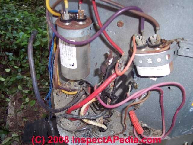
 Electric Motor Start / Run Capacitor Operation
Install Air Conditioning Compressor Motor & Other Electric Motor Start-Boost or Run Capacitors
- POST a QUESTION or COMMENT about installing a hard-start capacitor to get an air conditioner motor, fan motor, or other electric motor running.
How does an electric motor capacitor work? This article gives a short simple explanation of how a motor starting capacitor or motor run capacitor actually works to get a motor spinning or to keep it spinning efficiently.
Capacitors are electric devices that get an electric motor running at start-up or that help keep a motor running once it has started. If the capacitor has failed the most common symptom is that the motor won't start.
InspectAPedia tolerates no conflicts of interest. We have no relationship with advertisers, products, or services discussed at this website.
- Daniel Friedman, Publisher/Editor/Author - See WHO ARE WE?
Explanation of How a Starting Capacitor or Booster for Hard Starting Air Conditioners Works
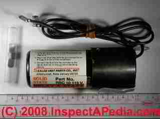 Capacitors are electric devices that get an electric motor running at start-up by providing a "jolt" of stored electrical energy, or that help keep a motor spinning once it has started.
[Click to enlarge any image]
The starting capacitor, used on many 120V or 240V single-phase electric motors such as air conditioning compressors, refrigerators and well pumps that require a high starting torque, helps a motor start spinning by creating a high-torque, rotating, electrical field in the motor. Motors that operate using this method are called a single-phase capacitor-start-run electric motor.
To deliver that starting kick or torque boost, a motor that uses a start capacitor will have a high microfarad (MFD or µF) rating compared to the run capacitor used for the same motor. Electrolytic type starting capacitors are designed only for intermittent use (each time the motor starts), so the start capacitor must be switched off as the motor approaches running speed.
In capacitor-start, capacitor-run electric motors, a second, smaller capacitor, the run capacitor, helps keep the motor rotating once it has achieved operating speed.
Starting capacitors extend electric motor or HVACR compressor motor life, and surprising to non-engineers, a hard start compressor actually reduces the operating cost of the equipment it is serving by reducing the in-rush of current during the start-up phase of motor operation.
But starting capacitors themselves can fail for any of several reasons including exposure to harsh conditions, weather, corrosion, loose connections, failure of a centrifugal switch used to switch off the start capacitor when the motor is spinning, or improper control, selection, or use.
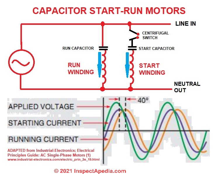 If the start capacitor has failed the symptom is that the motor won't start. If either or both start and run capacitors are defective the motor may try to start but will hum and won't keep running.
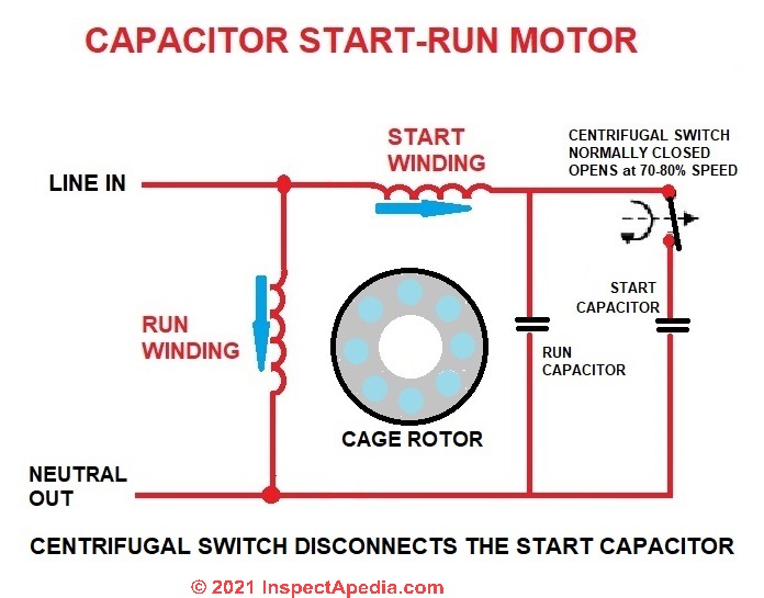
Our illustration shows that the start and run windings in this capacitor-start electric motor are connected in parallel. The centrifugal switch cuts out both the start capacitor and the start winding as the motor speeds-up.
This is a simplified conceptual drawing and is not technically exhaustive.
A key concept is that the start and run windings are built 90° out of electrical phase with one another in the motor, so that the aux or start winding can give an extra push to help the motor begin to spin regardless of the position the motor was in when it stopped.
That design is evident in the phase differences depicted by the purple starting-current curve and the orange running current phase curve. These motor power curves are adapted and from Electrical Principles Guide: AC Single-Phase Motors by Industrial Electronics.
In induction electric motors like the A/C or heat pump compressor motors mentioned above, both the start capacitor and start winding or auxiliary winding are switched off by a centrifugal switch when the motor reaches 70-80% of its full running speed.
Watch out: If you observe a humming electric motor that is not starting we suggest that to avoid damage you turn off the system while waiting for repairs.
Note: Many electric motors are designed to operate without using a starting capacitor.
See those explained
at ELECTRIC MOTOR TYPES - 8 types of single phase, split phase, 2 & 3 phase motors
Electric motor starting capacitors are only very rarely present on small refrigeration compressors, such as those in refrigerators, and as far as we know, never present on 3-phase power systems.
The drawing below is more-technically-accurate in that it shows that the start winding and run winding are oriented 90 degrees apart in the motor - or to produce electrical fields at right angles to one another.
This electric motor drawing also shows a different capacitor start/run design in which the start capacitor turned off once the motor reaches 70-80% of its full run-speed.
For a motor designed to run at 3450 rpm, this means the start cap should cut out at about 2400 rpm, and for a 1725 rpm electric motor the starting capacitor should cut out at or above about 1200 rpm.
In this design if the centrifugal switch fails to open when it should (at higher motor speed) the starting capacitor will be destroyed.
How & Why Does a Start Capacitor Help an Electric Motor Start?
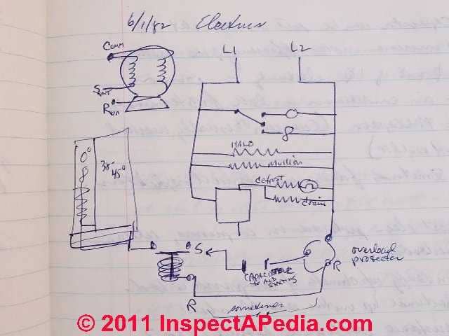 Our little sketch of a basic refrigeration circuit shown at left illustrates where and how a starting capacitor fits into a refrigeration or air conditioning electrical circuit.
The starting capacitor works by "accumulating" a large electrical charge inside the capacitor. During compressor or other motor startup, the start capacitor releases its charge to give a voltage "boost" to get the electric motor spinning.
During an electric motor start-up (such as an air conditioner compressor motor and some fan motors) where a starting capacitor is included in the circuit, with the added charge stored in the capacitor, run-start and start-common voltages increase to a maximum value to start the motor spinning.
The total supply subsequently current drops back to normal run conditions when the start device is dropped from the circuit - the motor continues to run.
This "electrical starting booster charge" can be particularly needed if an air conditioner is suddenly switched off and back on when it has been operating.
Suddenly switching off an air conditioning compressor leaves a high "head pressure" inside the compressor which can provide extra mechanical resistance when the motor is attempting to re-start.
Traditionally electrical capacitors were also called "accumulators" for this reason.
The capacitor's electrical charge is released at motor start-up time, gives the compressor motor or other electrical motor a boost for starting.
What makes a Start Capacitor Drop from the Circuit when the Motor has Started?
As we explain at CAPACITOR SIZE DETERMINATION for ELECTRIC MOTORS, once a starting capacitor has provided the necessary boost to get the electric motor spinning, to avoid possible motor damage the capacitor has to drop from the electrical circuit, leaving the motor to run on normal operating current.
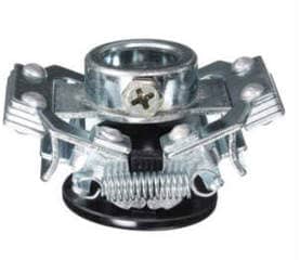
Typically a centrifugal switch or possibly a PTC or PRD drops the start capacitor from the motor's electrical circuit once the motor has spun up to operating speed. The centrifugal switch uses spring tension to keep the switch closed and the start capacitor in the motor circuit; when the motor reaches an appropriate speed it overcomes spring tension and the switch opens.
We illustrate and explain these special controls or features
at ELECTRIC MOTOR CAPACITOR SPECIAL FEATURES
Why Must a Start Capacitor Must Drop from the Circuit After the Motor Starts?
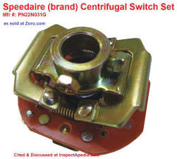 To avoid burning out the motor windings or the capacitor itself, the huge current delivered by the start capacitor has to be turned off once the electric motor is running.
There are two reasons the start capacitor can’t stay in the circuit full time.
1. The start winding of the compressor can’t carry such a heavy current continuously without overheating and burning out.
2. The start capacitors are made very compact and would overheat in a short while because they aren’t big enough to dissipate heat as rapidly as it’s generated.
The plastic casing on the start capacitor also plays a role in its tendency to overheat.
When a start capacitor does overheat, the little putty filled hole in the top of the capacitor blows and all the fluid inside runs out, causing the capacitor to fail. - SUPCO Hard Starts booklet cited below.
See also ELECTRIC MOTOR CENTRIFUGAL SWITCH or PTC PRD
Electric Motor Capacitor Special Features
Bleed-Through Resistors on Starting Capacitors
![Starting capacity with a 15K ohm [15K Ω 2W], 2 Watt Resistor (C) InspectApedia.com](Starting-Capacitor-Bleed-Down-Resistors.jpg) Some starting capacitors such as those designed by and used in Copeland HVACR compressor motors, include a bleed-through resistor wired between the capacitor's two terminals. Typically a 15K-18Kohm two-watt resistor is used for this purpose
Some starting capacitors such as those designed by and used in Copeland HVACR compressor motors, include a bleed-through resistor wired between the capacitor's two terminals. Typically a 15K-18Kohm two-watt resistor is used for this purpose
Copeland describes the bleed-through resistor as follows:
The use of capacitors without these resistors will result in sticking relay contacts and/or erratic relay operation especially where short cycling is likely to occur. This is due to the start capacitor discharging through the relay contacts as they close, following a very short running cycle.
The resistor permits the capacitor charge to bleed down at a much faster rate, preventing arcing and over-heating of the relay contacts.
... If sticking contacts are encountered on any start relay, the first item to check is the start capacitor resistor. If damaged, or not provided, install a new resistor, and clean the relay contacts or replace the relay.
Suitable resistors can be obtained from any electronic parts wholesaler or retailer. - Copeland Electrical Handbook p.A5- A6.
A pack of five 15K ohm [15K Ω 2W], 2 Watt Resistors from Electron Components, an online vendor in July 2018, sells for as little as less than $1.00 USD.
Centrifugal Switch Drops Starting Capacitor from Motor Circuit
A mechanical centrifugal switch may be used to disconnect the starting capacitor when the motor speed has reached a critical rpm, typically about half of the motor's run speed.[2]
PTC-devices Can Drop the Start Capacitor from a Circuit
Positive Temperature Coefficient devices are the traditional means of dropping the capacitor from the motor circuit once the motor has successfully started.
PTC devices have the advantage of being simple and avoiding the need for more complex electrical wiring of a motor starting system.
PRD Potential Relay Device + Hard Start Capacitors Boost Starting Torque for HVAC Motors on TXV-based systems
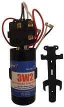
Potential Relay Devices use voltage sensing (The Supco method) or current sensing devices (two different approaches) to determine when to release the starting capacitor from the motor run circuit.
Supco points out that "The electronic potential relay is inherently more reliable and precise than the older type mechanical potential relay." [1]
The SUPCO booklet we cite below provides wiring connection details for 3-wire and 2-wire connected potential relay / hard start kits.
Details about all three of these devices are
at ELECTRIC MOTOR CENTRIFUGAL SWITCH or PTC PRD
Excerpt from SUPCO: Wiring & Using a 2-Wire Hard Start Kit on an HVACR Compressor
 A more convenient method for providing increased torque to the compressor is the 2-wire
potential relay hard start device.
In this case, the device can add as much starting torque as a 3-wire hard start, but installation is made simpler and cost is usually lower.
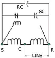
The Figure [shown here] illustrates the wiring diagram for a 2-wire hard start.
Two wire hard start kits are connected in parallel with the run capacitor for Permanent Split Capacitor (PSC) type compressors; and connected to the Start and Run terminals on the compressor for Capacitor Start Induction Run(CSIR) type compressors.
There is no need for a third connection to common wire.
The start relay has normally closed contacts, so when the compressor starts, both the run and start capacitors are connected to the start terminal.
This causes a very high current to go through the start winding when power is first applied. This high start current increases the starting torque of the compressor motor enough that the motor will start even though the refrigerant pressures haven’t equalized, or in an “under-voltage” condition.
Once the compressor begins running, the voltage across the start winding increases. This occurs because the motor acts partly like a generator and partly like a transformer.
The start relay coil is connected in parallel with the start winding. When the voltage across the start winding increases above the pick-up rating on the start relay coil, the start relay contacts open. The start capacitor is then out of the circuit. - SUPCO Hard Starts booklet cited below.
Start & Run & Dual Capacitor Sources & Reference Texts
- COPELAND ELECTRICAL HANDBOOK [PDF]
- Essex, Brown: "Motor Repair Supplies" (Catalog), Essex Group, Inc., 1601 Wall St., Fort Wayne, Indiana 46801, Tel: 219-461-4633, Website: www.superioressex.com, retrieved 6/20/14, original source: http://www.essexbrownell.com/uploadedFiles/Content/Products/MR%20Supplies%20Catalog-s.pdf - see pp. 86-89.
- Sealed Unit Parts Co., Inc., PO Box 21, 2230 Landmark Place, Allenwood NJ 08720, USA, Tel: 732-223-6644, Website: www.supco.com, Email: info@supcocom, Supco Catalog, retrieved 6/20/14, original source: http://www.economicelectricmotors.com/cdrom/catalogs/Supco_catalog.pdf - see pp. 2-6.
- van Roon, Tony, "Capacitors", [online article], retrieved 6/20/14, original source: http://www.sentex.ca/~mec1995/gadgets/caps/caps.html, gives a very detailed history of the invention and history of electrical capacitors beginning with van Musschenbroek's Leyden jar in 1745. This article includes
"Capacitor Nomenclature" by Dean Huster. - Kaiser, Cletus J., The Capacitor Handbook Book for sale at Amazon.com] A Comprehensive Guide For Correct Component Selection In All Circuit Applications. Know What To Use When And Where, 2d Ed., [at Amazon.com] C.J. Publishing (2011), ISBN-10: 0962852538, ISBN-13: 978-0962852534 - product description
This book provides practical guidance and application information when using capacitors in electronics and electrical circuit design. This easy-to-use book covers the following capacitor types: Ceramic, Plastic Film, Aluminum Electrolytic, Tantalum, Glass, Mica, and others. This book also has a very comprehensive Glossary and Index.
The Selection Guidelines and the Symbols and Equations sections have the answers to all of your daily application questions. This book is one in a series of component handbooks. - SUPCO AC Hard Starts, HARD START CAPACITOR BOOKLET [PDF], SUPCO, Sealed Unit Parts Co., Inc., PO Box 21, 2230 Landmark Place, Allenwood NJ 08720 USA, Tel: 732-223-6644, Website: www.supco.com, Email: info@supco.com retrieved 2018/07/11, original source: http://www.mcaair.com/docs/supco/hardstartbooklet.pdf
...
Reader Comments, Questions & Answers About The Article Above
Below you will find questions and answers previously posted on this page at its page bottom reader comment box.
Reader Q&A - also see RECOMMENDED ARTICLES & FAQs
On 2022-06-11 by InspectApedia-911 (mod) - can I wire a hard start capacitor to my gas dryer?
@Kyle,
Thank you for the added detail. That's helpful.
Have you actually measured the initial current draw?
Would a slow-trip breaker such as used on A/C or heat pumps work?
Also I'm still reluctant to add a fix when I'm not convinced that there isn't something else wrong that we haven't determined.
It doesn't make sense to me that you'd have a problem when connected to a higher-capacity power source that doesn't occur when you're connected to a lower capacity source.
On 2022-06-11 by Kyle
@InspectApedia
There is no problem with the dryer motors. Both of these lp gas dryers use a motor with start and run windings but no capacitors.
I have tried these dryers on grid power and generator power (3400w) and they work great. It's the solar system that I'm using (3000w with a 6000w peak inverter).
When you start the motor, the sudden inrush of current trips the inverter off. I need to find a way to either boost the start winding or possibly limit current to the motor somehow.
It's the 10x normal amp draw that happens for like a few milliseconds when I start the dryer that trips the inverter.
I have found a 120v inrush current limiter that I'm thinking of trying. It's an outlet box that limits the max current to 15a. I'm not sure how this works but I think I'll try that first. Thanks.
On 2022-06-10 by InspectApedia (mod)
@Kyle,
Thanks, that's a really interesting question. We both need to do some research. I don't think you would just arbitrarily add a start capacitor to an electric motor that doesn't use one.
I should say something important which is that we should diagnose the problem before we prescribe the fix.
For example, if your motor or wiring is shorted, or the motor has a failing bearing, you don't want to risk an electrical fire by just forcing the motor to run.
On 2022-06-09 by Kyle
I'm having a problem with starting my gas dryer on my 6000w 24v inverter. The second I hit the start button, the surge shuts off the inverter. Other appliances like my fridge don't cause this problem at all. I've come to the conclusion that most gas dryers use a motor without a start capacitor. I have tried multiple dryers and they always do the same thing yet when I run them on my 3400w generator they work fine.
My question is this. Is it possible to wire a hard start capacitor in line with this type of motor and if so, what type of capacitor should I use. I imagine if I could get one installed correctly, it should reduce the surge and voltage drop on my inverter when I start the dryer. Thank you for your time!
On 2021-08-23 by inspectapedia.com.moderator
@RJ,
see the diagnostic suggestions at ELECTRIC MOTOR DIAGNOSTIC GUIDE
On 2021-08-21 by RJ
Occasionally my compressor motor won't start, I can spin the fan and it comes on ok. I've changed the start capacitor, and the new one works about 2 to 4 times then doesn't, so I put the old one back in and it works for several months, then stops and I have to give it a spin to get it going and it will work between days or weeks again. What do you think. I'm thinking maybe a lose connection or bad wire some where affecting the capacitors charging or discharge.
On 2021-04-17 by danjoefriedman (mod) - capacitor is very inexpensive and easy to replace
@Anonymous,
That's got to be $190 in labor and $10 for the capacitor. It might be a plug-in repair part.
If your capacitor is in specifications it's easy to replace.
Watch out: Take care however; if you do not know how to do safe electrical repair and wiring you could be shocked or killed.
On 2021-04-17 by Anonymous
@danjoefriedman, they want over 200 dollars for the capacitor. So, I should probably buy it myself? And thanks for the immediate response. It’s my rental and I am 400 miles away from the unit
On 2021-04-17 by danjoefriedman (mod)
@Sharon,
A motor start or run capacitor is so inexpensive that in my opinion it makes no sense to fool around or delay or debate the question; just replace the capacitor(s) and you and the tech will know right off if the cap was the trouble.
Because of the cost of visits to a site along with labor costs and the time and trouble to more thoroughly diagnose a failing AC compressor or blower motor, it's common for a tech to just replace the capacitor;
Keep in mind that if the motor is failing a start-run capacitor might keep it going for a time, but the motor is going to fail hard.
On 2021-04-17 by Sharon
My AC tech is telling me my start/run capacitor is running below manufacture’s spec. Yet, he also says, the electrical components seemed to be working properly. The unit is about is about 3 years old. How important would it be to replace the capacitor, or could I let this slide without any damage to the unit as a whole?
On 2021-02-08 by danjoefriedman (mod)
Thanks, Johnny, that's an interesting idea; not a solution with which I am familiar; I'll see what I can find.
By "FF" are you referring to a food freezer or something else?
On 2021-02-08 by JohnnyK
Hi, is there an additional device that can simply be plugged inline on the AC side, powered by a DC battery running a pure sine wave AC inverter to ENHANCE the hard start facility of a capacitor start for a fridge / freezer?
The reason I ask: my FF works fine off AC mains in the UK. However I wish it to function from the above in a SHTF / grid-down situation. My setup above struggles to start the FF, but if started, it will then run the FF easily thereafter. There are many newly designed so called, solar generators with batteries sold throughout the USA that cannot start a FF for the same reason as my home setup.
Maybe someone could suggest a capacitor upgrade (bigger, more micro-farads?) or an inline wizzy-bang thingy that would give the start-up more oommmpphhh?
I've sort-of solved it myself, by adding extra batteries (more power / more voltage) & adjusting the AC output voltage of the pure sine-wave inverter to 250v AC, but I'd like a better method / solution, as my 12v car batteries won't maintain full power / voltage during bad days in the winter months using limited solar power on cloudy winter days.
On 2021-02-07 by (mod) - how do I buy a replacement motor capacitor?
 David: it looks to me as if your Daly capacitor (it's not a resistor) for use on an electric motor, probably as a "run" capacitor, gives 40-70 uF or "micro-Farads" of capacitance; that's the *range* over which it's expected to function.
Safest would be to find a cap with the exact same specs but you could get close enough; e.g. with a 70uF device. A common example is below.
[Click to enlarge any image]
The voltage is an upper limit, so your replacement could safely be 275 V or higher.
You'd buy an equivalent of the same uf and voltage range from any electronics or electrical supplier.
Just search for Motor Capacitor 70 uf 270V and you'll get in the right range of responses. These are not expensive parts.
Sorry, not from us. We do not sell anything. No products, no services.
InspectAPedia.com provides building and environmental diagnostic and repair information. In order to absolutely assure our readers that we write and report without bias we do not sell any products nor do we have any business or financial relationships that could create such conflicts of interest.
Wiring and capacitor selection guides are in the ARTICLE INDEX as well as in the Recommended Articles list above.
Watch out: if you are not familiar with safe electrical wiring you could be shocked or killed.
On 2021-02-07 by David
I need to replace the capacitors on my air compressor the info on the resistor is Daly, 40-70uf, 275 V RMS, MSHP1K452C, UK, UK MADE, I do not know why there are two uf numbers on the capacitors, but if you could supply me with two or assist me with a supplier I would be most grateful.
On 2021-01-18 by (mod) - what is an “InstaWatt” device, how does it work, and do such devices really reduce your electric utility bill?
Sam
Thank you for the helpful question that I’d re-phrase is what is an “InstaWatt” device, how does it work, and do such devices really reduce your electric utility bill?
The Insta-Watt "electrical power saver" is one of a class of devices sold to supposedly save on electrical usage and thus energy cost by using capacitor(s) to absorb or smooth peaks or surges in power as it is delivered by the electric utility. The device manufacturers say that un-stable surging electrical power wastes energy by simply converting it to heat.
Bottom line: these devices function as power conditioners, smoothing the delivery of power as voltage to the circuit where they are employed.
But an electrical engineering explanation demonstrates that the claims of “saving of 25% to 40% of your electric bill” will not be realised - these devices can not work in actual practice.
It is possible that consumers who report seeing a drop in their electric bills are actually seeing the effect of a more attentive use of such users to their own use of electrical devices.
Really?
That is because improving power quality does not improve the energy efficiency of your home appliances. (There are useful applications of power conditioners at certain industrial applications where such devices are installed right at the power-using equipment.)
More-technically, electric utilities charge their customer for actual power used, measured in KWH or kilowatt-hours. The utility does not charge for “apparent” power (measured in KVA) nor for “reactive power” KVAR, nor does your electric meter even record those latter two measures.
Electrical engineering experts explain that while there may be a possible, though probably modest, improvement in the efficiency with which a circuit protected by such a device is used, it's probably less than promised or believed by vendors or consumers.
The devices we're discussing typically are comprised of a control circuit and a collection of capacitors, similar to your guess. The capacitors smooth the delivery of electrical power to the using appliances by storing energy that arrives during peaks of fluctuating voltage.
That such devices work at all it's because the electrical power delivered to a consumer is not dead flat in voltage; there are voltage surges and dips. The extent or size and frequency of voltage fluctuations varies considerably for a number of reasons including peak demand, generator properties, distribution properties, and can considerably different depending on where you live. The electrical voltage level at our office in central Mexico varies more than at our office in New York, for example.
In essence you're installing a surge protector.
The Insta Watt is not identical to an electric motor start or run capacitor as those are sized and designed specifically to get a motor spinning (overcome initial torque) or to keep it spinning once started.
A thorough explanation and exploration of this question is provided by EEP the Engineering Power Portal and can be read at
https://electrical-engineering-portal.com/the-real-truth-behind-household-power-savers
where the writers explain the relationship of real power measured in watts, apparent power, power factor, and the difference between a resistive load energy use (such as an electric heater or light bulb having a power factor of 1) and inductive or capacitive loads such as electric motors that have a power factor of less than one. The claim is that the power saving device brings the efficiency of inductive or capacitive loads closer to the desired 1 found in resistive loads, thus reducing the total current use on such appliances (dishwashers, refrigerators, freezers, washing machines, etc.)
But your household electric bill won’t be reduced - because the “real power” or actual amount of energy use by the appliance (measured in KWH) remains un-changed - and it’s only KWH that is being monitored by your meter and charged-for by your electric company.
On 2021-01-17 by Sam Becker - Is the device "Insta Watt" just a motor run capacitor, plugged into a 110-vlot wall outlet?
Is the device "Insta Watt" just a motor run capacitor, plugged into a 110-vlot wall outlet?
On 2020-09-10 by (mod)
Bob
Normally you'd replace the existing cap with the hard-start capacitor;
Provided you choose a hard-start capacitor in the proper range for the AC motor's original cap, it won't damage the equipment.
See details at CHOOSE a START / RUN CAPACITOR, HOW TO https://inspectapedia.com/electric/Motor_Capacitor_Selection.php
Keep in mind that the very condition that makes one try a hard-start capacitor - that is, an electric motor that's having trouble starting-up - is often caused by an underlying failure in the motor itself, such as a failed bearing that causes rotational resistance that makes starting difficult. So it will be no surprise if such a motor later fails completely. The hard-start capacitor is in sum a temporary band-aid repair effort that sometimes lets us squeeze a bit more use out of a failing motor.
On 2020-09-10 by Bob
Will a hard start capacitor added to a standard capacitor (to assist in generator start) damage ac motor in reg household operation?
On 2020-07-25 by Graham
I am trying to fix a capacitor start motor. It "hums" on start-up until I turn it manually to start - then it runs OK (in either direction). Before I replace the capacitor I checked and found that there was a current running in the start coils (capacitor disconnected) so I suspect that the centrifugal switch is not opening and therefore the start coils are generating the current. Is this possible ?
On 2020-06-23 - by (mod) -
Joe please find your question and a stab at a reply now near the bottom of the article above. let me know if that helps or what questions or comments you can add.
On 2020-06-09 by Joe Bloe
If a start capacitor does not increase voltage, how does it provide a "boost" to the compressor. If it only applies voltage for a brief. To the start winding why would you even need a capacitor then it's a voltage has an increased why not just apply line voltage to the start winding briefly
On 2020-06-23 - by (mod) - why does my motor need a start capacitor?
Thanks for the great question, Joe.
The capacitor has also been called, especially in older literature, an "accumulator". Fed by voltage the capacitor accumulates and stores a electrical charge. When the capacitor's accumulated charge is released a very high voltage (think of volts here as "pressure") is sent to the motor to give it a start-up kick. That charge voltage is much much higher than the typical 120VAC or 240VAC line voltage.
A simple and maybe too-short answer is that while not all motors need or use a starting capacitor - as there are various designs, voltages, electrical phase driven motors - for a typical small electric single-phase motor such as used in HVACR or on well pumps and table saws, the motor needs an extra jolt or push to overcome some force or load to get the motor spinning.
The way reader Brandon put it below was:
A farad is 1 coulomb which when in motion becomes 1 amp. So a cap with 100 microfarads is only capable of storing 100th of an amp. It’s just adds resistance to the start winding the illusion of a “boost” in the circuit that hasn’t been altered.
The electric motor starting capacitor (classified as a capacitor rated between 25uf-1400 uf and at 125V, 250V, or 330V) is ONE way of boosting the starting torque (twisting force) applied to a single-phase electric motor. [uf = microfarad = MFD]
See CAPACITOR SIZE DETERMINATION for ELECTRIC MOTORS
for typical motor start and run capacitor sizes
The capacitor's "charge" is expressed in coulombs where
Q = CV
C = capacitance
V = voltage
Q = charge in Coulombs
The amount of energy stored in a capacitor is written as
W = ½ QV = ½ CV2
W = energy in Joules.
and
1 Electron volt (eV) = 1.602176565 x 10¹⁹ joules (J)
or put another way, converting between Volts and Joules,
V(V) = E(J) / Q(C)
where
V = Volts (V)
E = Energy in Joules (J)
Q = Charge (Q) expressed in Coulombs (C)
Continuing to explain the push or jolt to a motor from a starting capacitor,
A 1 f (Farad) Capacitor stores a charge of 1 Coulomb at 1 Volt
and
in Current or Amps,
a 1 Farad capacitor has stored 1 Amp-Second of Current (or electrons) at 1 Volt
So when the 1 Farad cap releases its charge to the motor it pushes the motor at 1 Amps at 1 Volt for 1 Farad of capacitance.
On 2020-06-09 by Joe Bloe - why not just apply line voltage to the start winding briefly
If a start capacitor does not increase voltage, how does it provide a "boost" to the compressor. If it only applies voltage for a brief. To the start winding why would you even need a capacitor then it's a voltage has an increased why not just apply line voltage to the start winding briefly
On 2020-01-06 - by KC - replacement capacitor for a 1 HP table saw motor
RE-posting from private email rec'd 12/20/2019 from K.C.
I have concerns about a replacement capacitor for a 1 HP table saw motor was manufactured by Driver Custom Built Motors for the Walker-Turner Division of Kearney & Trecker Corp. I believe the saw was manufactured around 1952. The Service Information Plate reads:
Frame - 120
Type - KEB10F
Amps - 19/9.5
Temp Rise - 40° C Cont(inuous)
H.P. - 1
Volts - 115/230
Cyc(les) - 60
Phase - 1
R.P.M. - 3450
The capacitor (I assume it is a start capacitor) information (not the original):
Cornell-Dublier
341 - 4112 MFD
110 VAC
60 HZ
HF
ETW 10079
Size is 1 13/16" D x 4 3/8" L (Case Code 5)
The motor was rewound about 45 years ago and the capacitor was replaced with the Cornell-Dubilier (has a resister installed between the terminals). The capacitor is going/gone bad and the saw will not start without a "helping spin." Tricky at best to keep fingers intact!
The motor is wired to run with 230 volts (220 actual). I think I recall I had to change the wiring from the 110 terminals back to the 220 terminal after it was rewound. The saw has been working in the mode described since the rebuild.
I have checked on line and do not find an exact replacement for the existing. The closest Cornell-Dubilier is 340 - 408 MFD, 110/125 volt, Case Code 4 (1 13/16" x 3 3/8"), Catalog Part Number PSU34015.
The closest with a Case Code 5 (like the one on the motor) with the same MFD rating is rated for 165 volts (Part Number PSU43065).
BUT, based my understanding of your information and explanation related to replacing a motor start capacitor, that with the motor being run at 220 volts / 9.5 Amps, a capacitor with a capacity to run at 25/250 volts should be used. If that is correct, what MFD should I use? I think I understand that the MFD at 220 volts is much lower than what is required at 110 volts since the motor is much easier to start (9.5 Amps). But, it does not appear to necessarily be a linear MFD reduction. That is where I get lost in the weeds and need assistance.
First - I am assuming this is a Start Capacitor, not a combined Start/Run Capacitor.
Second - What capacitor and MFD is recommended for this motor set up at "230" Volts? I was not attempting to necessarily replace with a Cornell-Dubilier, but found the information for a go-by. Also, the the length of a replacement can be reduced and still fit the mounting bracket. But, the diameter needs to remain the 1 13/16" to fit the end caps (attachment wires run through one of the end caps) and bracket.
Third - I assume I can remove the resister that is on the existing capacitor and reuse it.
Any and all information to resolve my dilemma will be greatly appreciated.
On 2020-01-04 by (mod) -
Thanks Brandon; indeed one of the reasons I research and write is to learn by the process. To explain requires understanding.
On 2020-01-04 by Brandon
Very true about the way electricity works. It’s all theoretical physics. Movement of the electron, and we have never seen an electron, were just pretty dang sure it exists because we see the effects. I’ll say based on your article you clearly have a commanding practical understanding of electric motors. Knowing something is easier than teaching someone who doesn’t know. I appreciate having this conversation with you.
On 2020-01-04 by (mod) -
I certainly agree in principle. Years ago I sat in a room with six fellow electrical engineers and turned to one, Trudi Kappel who had a phD in the topic, and asked "So Trudi, how does electricity actually really work?"
Her answer: "Well we really can't say exactly" ... which deteriorated into a six-way argument about electrons and force, current, potential, ultimately quantum physics.
I appreciate that we certainly don't want to mislead or get folks in trouble on the topic. I appreciate your comments.
On 2020-01-04 by Brandon
That explanation you just made I feel is true enough without needing degree. But just because something is the middle ground doesn’t mean it’s correct. The way electricity works is not up for debate simply because it may be harder to understand.
I do appreciate the fact that your trying to educate people, so let’s educate them with the correct knowledge. It’s worth understanding.
The hardest part for me to understand electricity was simply getting to the point to realize 90% of information out their is wrong and won’t allow for actual understanding of your mind is clouded with misinformation from an otherwise great source.
On 2020-01-04 by (mod) -
I appreciate the argument for accuracy and clarity. When there's enough here I'll edit the article accordingly.
On 2020-01-04 by (mod) - Basics of Starting Capacitors & Centrifugal Switch in Electric Motors
Thank you Brandon for that added and more-technically-accurate detail on how a capacitor-start electric motor works.
There is some danger is making it so correct as to confuse a non-electrician, right?
Simple Explanation of how a start capacitor gets a motor spinning
A single-coil AC induction motor's pulsating field (AC means 60 cycle power fluctuating between + 120VAC to 0 to - 120VAC 60 times a second) can keep a motor spinning but can't get it started, so we'd need some external force to get the motor spinning at start time.
Typically we do this by adding a second coil (a coil is a wire round about an axis) - a START COIL or "start winding" - that will create a magnetic field (when energized) to push the motor to get it started.
The starting capacitor "lags" the electrical current or puts it out of phase with the "run" current to the motor so that the two can work together to spin the motor.
Typically these motors have a centrifugal switch ( a switch that will open when it's spun at sufficient speed) that opens to take the start coil or aux coil out of the circuit once the motor is up to speed.
Together those components are in essence giving the motor a "push" or as some writers say a "kick" to get it started.
That's the simplest design though not the most-efficient.
A "fancier" design includes an aux coil that stays in operation as the motor is running, assisted by a "run" capacitor that requires and uses less power once the motor has started. So this design will have either two capacitors (a bigger "start" cap and a smaller "run" cap) or a single physical device that combines the two (a "Start-Run") cap.
Most writers simplify this a bit from the truth. Perhaps we need to make the article suit two audiences.
On 2020-01-04 by Brandon citing John R Duff third edition chapter 18 principle of operation single phase motors
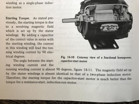
“By adding a capacitor of the correct value in series with the start winding, the current in this winding will lead the current in the run winding by 90 electrical degrees. The angle between the stating winding and the running winding is almost 90 degrees.
The magnetic field set up by the stator windings is almost identical to that of a two phase induction motor. Therefore, the starting torque for the capacitor start motor is much better than the torque of resistance start induction run motor”- source alternating current fundamental John R Duff third edition chapter 18 principle of operation single phase motors.
Here is more-technically-accurate explanation of how a starting capacitor works
Please read the excerpt, nothing about boosting here.
It’s a misconception of how the capacitor works in relation to a AC motor.
Excerpting from the above more-technically-accurate description of how a capacitor-start motor works, you will read that the motor start capacitor provides additional starting torque to the motor.
[Electric motor] Starting Torque
... the starting torque is due to a revolving magnetic field which is set up by the stator windings. By adding a capacitor of the correct value in series with the starting winding, the current in this winding will lead the running winding current by 90 electrical degrees.
The angle between the starting winding current and the running winding current is almost 90 degrees (figure 18-11, not shown here). The magnetic field set up by the stator windings is almost identical to that of a two-phase induction motor. Therefore the starting torque for the capacitor-start motor is much better than the torque for a resistance-start, induction motor.
On 2020-01-04 by Brandon
2-3 are completely wrong. If you think your right please go into more detail like I did.
On 2020-01-04 by (mod)
Brandon
The basic things we want read readers to understand here is
1. an electrical capacitor is a device that stores an electrical charge
2. when a motor is starting up, that electrical charge is used (or "discharged") to give the motor a "kick" to help it get spinning
3. a smaller capacitor (combined or as a separate device) is used to help keep the motor spinning once it's started
Unlike a battery (that also stores an electrical charge) a capacitor's job is to give a big push or a big jolt of power over a short time.
We can recommend a couple of books whose explanation is easy to follow:
Blume, Steven W. Electric power system basics for the nonelectrical professional. John Wiley & Sons, 2016.
Rozanov, Yuriy, Sergey E. Ryvkin, Evgeny Chaplygin, and Pavel Voronin. Power electronics basics: operating principles, design, formulas, and applications. CRC press, 2015.
On 2020-01-04 by Brandon
Thanks for reading, it’s important to say that this misinformation is out there because it’s like a game of telephone, and analogy that got way out of hand to explain very complex things. I also will say my explanation isn’t perfect as I was typing it out on my phone off the cuff.
Making a comment on how electric motors work is like saying how long is a piece of string is, depends on the string, I’m biased to give information on capacitor start capacitor run motors which behave slightly differently than say a ceiling fan motor. If you really want to know how electric motors work, buy a few textbooks on Amazon
On 2020-01-03 by (mod) - almost the entire explanation of how a start capacitor is wrong.
Thank you very much for your comments Brandon
On 2020-01-01 by Brandon
almost the entire explanation of how a start capacitor is wrong.
It works by adding capacitive resistance to the circuit, that will alter the time the start winding is energized vs the run winding. That difference in time between the start and run winding energization is what creates the rotating magnetic field. Once the rotor is rotating it can drop out the run cap in 1/10th of a second. A start cap cannot “boost” it can only hold a charge. So if it’s charged with 120v it will only let out 120v
A farad is 1 coulomb which when in motion becomes 1 amp. So a cap with 100 microfarads is only capable of storing 100th of an amp. It’s just adds resistance to the start winding the illusion of a “boost” in the circuit that hasn’t been altered.
A run capacitor allows the start/auxiliary winding to pricing a small amount of energy to the motor (around 5% maybe) it’s mostly to smooth motor operation
On 2017-06-26 by Wayne
Need help with wiring the capacitor in on my 2hp bench grinder. It has a power switch, centrifugal switch, capacitor, two main windings, and a start winding
On 2016-05-19 by Lou
Can I use a 3 in 1 capacitor to start a soda machine compressor?
On 2016-05-09 by (mod) -
Jim I'm answering beyond my expertise so this is just a guess: I think that up to a limit you can oversize a starting cap but if you go too far you simply burn up a seized motor or component.
Keep in mind that a starting cap may be simply giving a kick to a normally-operating motor, or it may be giving a big kick in the seat to an electrical motor in trouble, such as a hard-starting AC compressor. In the latter case, something is failing in the motor, maybe a bearing, and we're getting a bit more life by giving the hard-starting motor an extra push. But too big a push on a motor that's seized could cause something ugly to flare up.
An SPP6E is rated for 1/2 - 3 Horsepower Range, 88-106F Capacitor Size
An SPP8E is rated for 1-10 Horsepower.
So I think that on a 1 HP motor, either starting cap is in-range. But on a 1/2HP motor the 8E might cause or permit damage.
In sum, take a look at the voltage, HP, and F (Farad) range of the capacitors and check those against the original cap and/or the motor data plate info.
On 2016-05-09 by Jim Mcconn
If adding a hard start capacitor, SPP6 to an rv air conditioner enables it to start on a small (3000 watt) generator sometimes would an SPP8E not give it even more help starting? Could the SPP8e damage the compressor?
Thank you
On 2015-12-31 by (mod) -
Sorry I don't know what a stamp switch is.
On 2015-12-31 by Ken sylvester
Where can I buy a stamp switch for a 1 hp 110 V electric motor
On 2015-04-16 by Jerry Trainello
Thank you for a very well presented illustration on "Capacitors".
Question:
(Feb 21, 2014) Anonymous said:
is it possible to rebuild a submersible well pump
Reply:
Yes ... maybe; it depends on the condition of the pump casing, parts, an in my opinion, an accurate diagnosis of the trouble; at some point rebuilding is not cost effective. Indeed there are specialists (H Shreck in Poughkeepsie used to be one of them) who rebuild electric motors of all kinds.
There are also many water pumps whose design makes it quite reasonable to replace pump impellers.
So to answer your question, I dunno - it depends on what's broken.
Question: fan will start but won't keep running.
(June 1, 2014) Anonymous said:
The fan on my Conquest 80 will not stay on (interior fan). It starts and then stops after a few seconds. It was installed in 2005. Help.
Reply:
Anon,
The start capacitor is for getting a motor started, not keeping it running.
Often motors have two windings, a start winding and a run winding. Your motor's run winding may be damaged.
Or your fan motor may require a dual capacitor (start and run) or a separate run capacitor to keep it spinning.
Or your system may have a faulty control.
Question: will a hard start capacitor reduce current drawn and stop tripping a breaker
(June 7, 2014) Joel said:
I have a commercial hood & exhaust fan (120v) running in a food truck that is used for catering. We occasionally need to run off a generator (3000w) and we've found that the fan cause the generator overload to trip.
The fan has been tested and observed to draw 8 amps running at full speed. Given this, would it be possible to add a hard start kit, such as SUPCO SPP4E? Will need to confirm the motor size, just wondering if this would help.
The total draw of all items is less than 20 amps and the generator is capable of supplying 25 amps constant.
Thanks for the advice.
Reply:
Joel I think the problem lies elsewhere and needs some further diagnostics. I suspect that your total current draw is exceeding the ability of the generator - you may be running more than the fan, such as lighting, a cooler, toasters, other electrical appliances. If it were just the fan, drawing 8A, it has no business tripping the breaker.
Put another way if the problem is the fan and there are NO other appliances running, then there is a failing fan motor drawing high current, or an electrical short circuit or other unsafe condition to find and fix.
A start capacitor or a run capacitor won't change the current drawn by the motor.
...
Continue reading at TEST a MOTOR START or RUN CAPACITOR or select a topic from the closely-related articles below, or see the complete ARTICLE INDEX.
Or see these
Recommended Articles
- BASIC ELECTRICAL TESTS for BURNED OUT COMPRESSOR MOTORS
- CAPACITOR TYPES, for MOTORS
- CAPACITORS for HARD STARTING MOTORS
- CAUSES of HARD STARTING ELECTRIC MOTORS
- CAPACITOR SIZE DETERMINATION for ELECTRIC MOTORS
- COPELAND ELECTRICAL HANDBOOK [PDF]
- HARD STARTING COMPRESSOR MOTORS
- HOW a STARTING CAPACITOR WORKS
- HOW to TEST the MOTOR to ID TERMINALS
- LOCATE the STARTING CAPACITOR
- MOTOR CAPACITOR WIRING GUIDE
- STARTING CAPACITOR SAFETY
- TEST a MOTOR START or RUN CAPACITOR
- ELECTRIC MOTOR CENTRIFUGAL SWITCH or PTC PRD
- ELECTRIC MOTOR DIAGNOSTIC GUIDE
- HARD STARTING ELECTRIC MOTOR CAUSES
Suggested citation for this web page
HOW a STARTING CAPACITOR WORKS at InspectApedia.com - online encyclopedia of building & environmental inspection, testing, diagnosis, repair, & problem prevention advice.
Or see this
INDEX to RELATED ARTICLES: ARTICLE INDEX to ELECTRICAL INSPECTION & TESTING
Or use the SEARCH BOX found below to Ask a Question or Search InspectApedia
Ask a Question or Search InspectApedia
Try the search box just below, or if you prefer, post a question or comment in the Comments box below and we will respond promptly.
Search the InspectApedia website
Note: appearance of your Comment below may be delayed: if your comment contains an image, photograph, web link, or text that looks to the software as if it might be a web link, your posting will appear after it has been approved by a moderator. Apologies for the delay.
Only one image can be added per comment but you can post as many comments, and therefore images, as you like.
You will not receive a notification when a response to your question has been posted.
Please bookmark this page to make it easy for you to check back for our response.
IF above you see "Comment Form is loading comments..." then COMMENT BOX - countable.ca / bawkbox.com IS NOT WORKING.
In any case you are welcome to send an email directly to us at InspectApedia.com at editor@inspectApedia.com
We'll reply to you directly. Please help us help you by noting, in your email, the URL of the InspectApedia page where you wanted to comment.
Citations & References
In addition to any citations in the article above, a full list is available on request.
- Supco, Sealed Unit Parts Company, PO Box 21, 2230 Landmark Place, Allenwood, New Jersey, 08720, Tel: 732-223-6644, 201-449-3300, email: info@supco.com, provided the compressor starting capacitor and packaging information (purchased by the author from an air conditioning parts supplier in New York) - our example uses a Sealed Unit Parts Company Solid State part No. RSC 10 115V starting capacitor which was designed for installation on refrigerators and freezers. See www.supco.com/
- Industrial Electronics, ELECTRICAL PRINCIPLES GUIDE: AC SINGLE-PHASE MOTORS [PDF] retrieved 2021/11/30, original source: http://www.industrial-electronics.com/electric_prin_2e_19.html
We attempted to obtain contact information for this company but their home page does not identify authors nor could we find contact information. - [1] "The E Class Advantage", Supco (op cit), describes the company's advanced start/run capacitor products. Web search 08/04/2011, original source: http://www.supco.com/eclassadvantage.htm Quoting from that article:
The SUPCO E-Class Series comprise the most advanced developments in start device technology:
1. Voltage sensing technology that monitors for motor start (current sensing devices require internal fuse protection).
2. A 2-wire connection that simplifies installation
3. A secondary timing circuit that ensures that the capacitor is not permanently left in the start winding circuit
4. A fully electronic device - minimizing the limitations of mechanical devices and secondary fusing associated with triac devices
5. A start device matched with an appropriately sized capacitor to cover the range of compressors for the intended application (one size does not fit all)The use of compressor start devices results from a need to ensure that a compressor (usually air conditioning) will start under voltage conditions that are less than ideal. As discussed, several options exist in the market to address compressor start concerns. Start devices exist in many forms for specific applications.
SUPCO provides a full range of products in all relevant technologies to effectively match the proper start device to the application. Care should be taken to utilize a device that meets the requirements of the job. Extra caution should be observed when employing the "one-size-fits-all" and "a bigger capacitor is better" approach to applying a start device. Consult SUPCO, a manufacturer with a complete product range, to ensure the greatest success in the start device application. - [2] "Motor Start and Run Capacitors", AFCAP (African Capacitors Limited), web search 08/05/2011, original source: http://www.afcap.co.za/manual/Part2.pdf
- COPELAND ELECTRICAL HANDBOOK [PDF] free download from Emerson Climate Controls, at InspectApedia.com
- [3] "Kenmore model 580. 75121 room unit air conditioner wiring diagram", Sears Roebuck window air conditioner wiring diagram for a typical room or window air conditioner
- George Fazio, reader, contributed comments on failed starter capacitor diagnosis by noting the bulged capacitor ends. 09/25/2009
- Troubleshooting Compressor Problems," Henry Puzio, Fuel Oil & Oil Heat with Air Conditioning Magazine, June 1993, p. 39
Tom Morris, Engineer, capacitor discussion and correction to the original data. Email to D Friedman 5/29/2006 - Thanks Tom for critical editing. The text above explaining about capacitors was suggested by Mr. Morris. The original text of the 1993 compressor diagnosis article had the resistance explanation backwards. - Thanks to reader Diane McGivney for asking about air conditioner compressor motor starting capacitor costs and typical air conditioner service call fees - (May 2010)
- Thanks to reader James Oiler for reporting on the replacement of a heat pump starter capacitor, August 2010.
- Modern Refrigeration and Air Conditioning, A. D. Althouse, C.H. Turnquist, A. Bracciano, Goodheart-Willcox Co., 1982
- Principles of Refrigeration, R. Warren Marsh, C. Thomas Olivo, Delmar Publishers, 1979
- "Air Conditioning & Refrigeration I & II", BOCES Education, Warren Hilliard (instructor), Poughkeepsie, New York, May - July 1982, [classroom notes from air conditioning and refrigeration maintenance and repair course attended by the website author]
- In addition to citations & references found in this article, see the research citations given at the end of the related articles found at our suggested
CONTINUE READING or RECOMMENDED ARTICLES.
- Carson, Dunlop & Associates Ltd., 120 Carlton Street Suite 407, Toronto ON M5A 4K2. Tel: (416) 964-9415 1-800-268-7070 Email: info@carsondunlop.com. Alan Carson is a past president of ASHI, the American Society of Home Inspectors.
Thanks to Alan Carson and Bob Dunlop, for permission for InspectAPedia to use text excerpts from The HOME REFERENCE BOOK - the Encyclopedia of Homes and to use illustrations from The ILLUSTRATED HOME .
Carson Dunlop Associates provides extensive home inspection education and report writing material. In gratitude we provide links to tsome Carson Dunlop Associates products and services.


