Copper-Clad Aluminum Wire Safety & History
Comments on the history, testing, & safety of Copper-Clad Aluminum electrical wiring
- POST a QUESTION or COMMENT about Copper-Clad Aluminum electrical wiring
Copper-Clad Aluminum Electrical Wiring identification, safety, production methods.
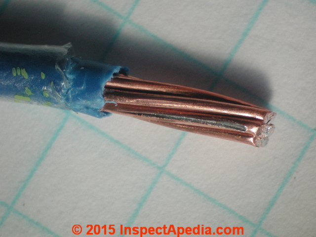
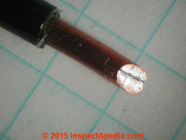
This article describes the history of copper-clad aluminum electrical wiring and its safe use in homes in the United States. Photo at page top: a #10 copper-clad aluminum electrical wire showing the stripped and cut end. Click to enlarge the image and you can see the thickness of the copper cladding around the solid aluminum conductor core of this wire.
InspectAPedia tolerates no conflicts of interest. We have no relationship with advertisers, products, or services discussed at this website.
- Daniel Friedman, Publisher/Editor/Author - See WHO ARE WE?
Copper-Clad Aluminum Electrical Wiring
 Thomas J. D'Agostino, P.E., C.I., & Daniel Friedman updated 2016/09/26 2018/11/18
The photograph of copper-clad aluminum wiring shown above illustrates this product installed in a installed in a Minnesota home: photo provided by and used with permission of Roger Hankey, a Minnesota home inspector.
Article Contents
- DEFINITION of COPPER-CLAD ALUMINUM WIRE
- IS COPPER-CLAD ALUMINUM WIRE SAFE?
- HOW to IDENTIFY COPPER-CLAD ALUMINUM WIRE
- HISTORY of COPPER CLAD ALUMINUM WIRE
- COPPER-CLAD ALUMINUM vs TINNED COPPER vs CU/AL or COALR
- COPPER CLAD ALUMINUM ELECTRICAL WIRE RESEARCH
What is copper-clad aluminum wire?
 Copper-clad aluminum wire is made of a solid aluminum core covered with a copper skin in order to improve its performance in the field. This product was installed in homes in the United States between 1972 and 1975.
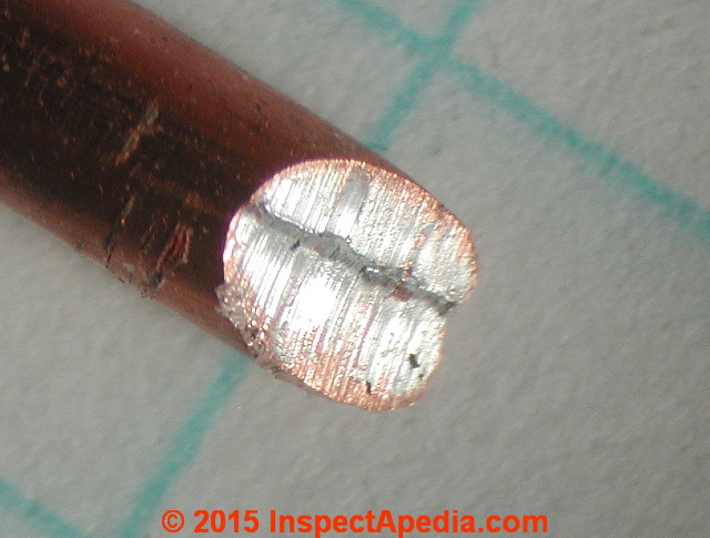
Above you can see a close-up of a typical end-cut of a #10 copper clad aluminum wire. The image shows the thickness of the copper cladding (yellow arrow) as well as cut marks across the end of the wire's aluminum conductor (white arrow).
In fact a small amount of the copper cladding was smeared across the cut wire-end by the wire-cutting process as you might notice at the lower edge of the cut edge above the "COR" in the word "CORE".
Some details about copper-clad aluminum wiring are provided by Tom D'Agostino:
Copper clad aluminum electrical wire is comprised of a solid aluminum core covered with a thin clad of copper. Approximately 10 percent of the cross-sectional area of the conductor is copper clad, thickness is not specified.
This product (only wire size Nos. 12-10 AWG), was designed by Texas Instruments for use with standard copper-only wiring devices, ie. switches, receptacles (binding head screw, back-wired, and pressure plate type terminals) and was treated as "aluminum" conductor for use in AL-CU pressure wire connectors in response to field failures of solid aluminum conductor branch circuit wiring. - D'Agostino (2014)
I would not assume that copper-clad AL wire might not appear in an older home in which electrical wiring was added or changed during that same interval, and it's also possible, though less likely, that copper clad aluminum wire might appear in new home built after 1975 if an electrician had and wished to use up old copper-clad aluminum wire stock.
Is copper-clad aluminum wire safe to leave in place?
Yes. Copper-clad aluminum electrical wire is described in REDUCE THE AL WIRE RISK: DETAILS, as well as in Aronstein (2011). There Aronstein states
Copper-clad aluminum wire (Nos. 12-10 AWG) has a thin copper outer skin and a core of aluminum. Therefore when installed and where visible in the main electrical service panel, it looks like "fat" copper wire (i.e., 10-12 AWG v. 12-14 AWG) and on the cut end, the copper skin looks to be "smeared" over the aluminum core.
Markings on the cable jacket would include "Al" or "Aluminum". There is no known history of connection overheating problems associated with copper-clad aluminum wire. No corrective actions are required for copper-clad aluminum wire. - Aronstein (2011), D'Agostino (2014)
Above: Renolds Aluminex 12/2 AL (CU-CLAD) With Ground copper-clad aluminum electrical wiring, courtesy Lawrence Transue, cited below.
[Click to enlarge any image]
How to identify copper-clad aluminum wire
Recognizing that electrical wire is copper clad aluminum is useful for technical reasons. For example, the wire gauge or diameter sizes of copper clad aluminum wire will follow the same physical sizes as for solid core aluminum wiring. A 15 Amp electrical circuit would have been wired with #12 aluminum wire, #12 copper-clad aluminum wire, or with #14 solid copper wire.
We summarize these wire sizes for aluminum and copper and copper-clad wire at SIZE of WIRE REQUIRED for ELECTRICAL RECEPTACLES for common household branch circuit wiring, and also at SE CABLE & BRANCH CIRCUIT WIRE SIZES vs AMPS including wire sizes from #14 AWG through 4/0 AWG.
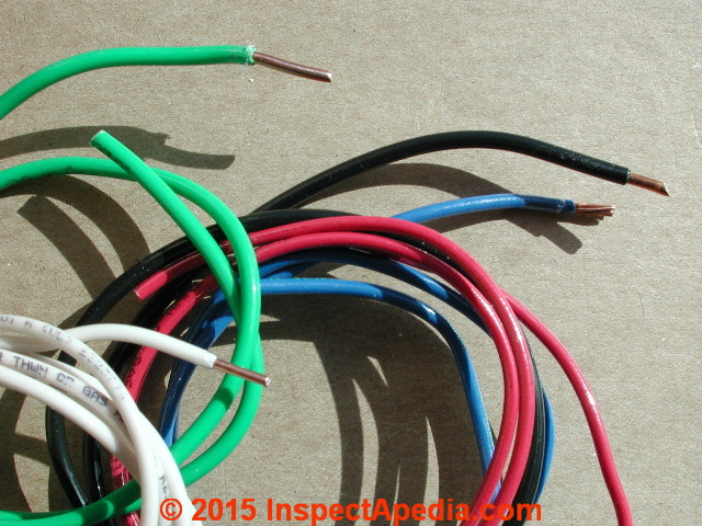
Externally, if we eschew noticing printed labels and marking that may be present on copper clad aluminum wire, and if we simply look at the wire itself, stripped of insulation, the wire looks like a copper.
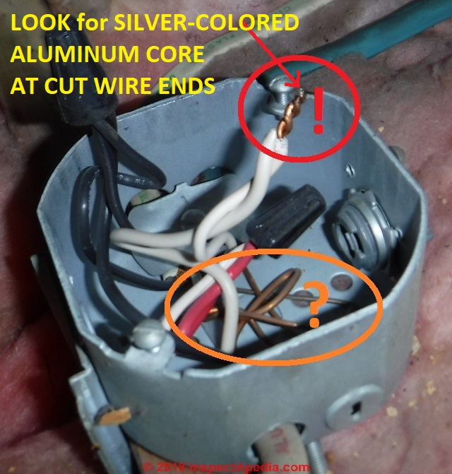
Below, in our photograph of Renolds Aluminex 12/2 AL (CU-CLAD) With Ground copper-clad aluminum electrical wiring (Lawrence Transue) shows what looks like a bare copper ground wire (circled in orange) in the bottom of the electrical box, and what on casual inspection looks like a pair of twisted copper neutral wires (circled in red) with the twist-on connector removed. ,
Click to enlarge this photo and look closely at the cut-ends of the "copper" wire and you'll notice that the cut ends look silver - a telltale sign of the wire's aluminum core.
That silver cut-end is always present but can be difficult to spot, for two reasons:
- Oxidation grays the aluminum:
Older wiring copper clad aluminum wire ends that were originally shiny silver when first-cut will have oxidized to a gray color that's easy to miss.
And just about any copper clad aluminum wire you find in buildings today will be old. - Tapered-extruded copper covers the aluminum:
The silver-colored aluminum wire ends wll also be obscured by the wire's exterior copper cladding that is often extruded by the wire nippers when the wire is cut.
When the CU-CLAD AL wire was originally cut the wire cutters do not produce a square-cut wire end.
Rather the wire end is pinched onto an angle, further extruding the copper cladding over the aluminum that might be visible on the wire end.
However if we can take a closer look at a relatively square-cut end of the wire we should see an aluminum core surrounded by a copper skin.
For my [DF] photos shown below I filed the wire ends flat in order to make the aluminum wire core more-visible.
Watch out: filing wire ends to show the aluminum core is not something that a home inspector or electrical inspector will normally do in the field. Obviously you'd need to turn off electrical power to the circuit first to avoid a nasty shock.
Without disassembly and possibly even careful cutting of the end of the wire this detail may not be easily visible, since typical wire nippers compress the end of the wire when making a cut.
Scraping copper clad aluminum wire may not be adequate to identify its silver-colored aluminum core unless the scrape is vigorous enough to cut completely through the copper cladding.
Above: #12 multi-strand copper-clad aluminum electrical wire. Click to enlarge this photo and you'll see that when I [DF] stripped the wire my stripping tool produced a long horizontal gouge on one of the wire strands, exposing the aluminum through the copper cladding.
Both Aronstein and D'Agostino suggest that nicks and scratches such as this won't prevent successful use of the wire as there is plenty of other copper-clad wire surface available to be in contact with the wire connector. Below, a close-up of the cut-ends of this wire product.
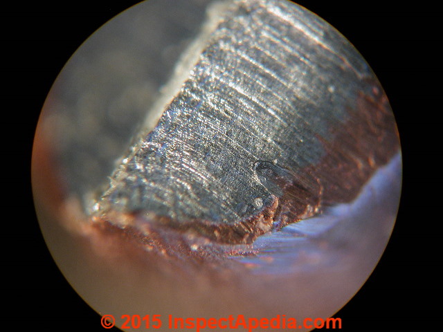
Below we illustrate the typical end of a copper-clad aluminum wire that was cut using a wiring tool, magnified about 120x.
You can see that the copper "skin" on the aluminum wire surface is rather thick. (The entire field of view is about 1.5mm).
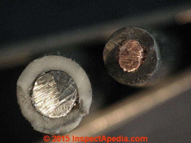
Let's compare the copper clad wire cross-cut image (above) with solid aluminum and solid copper wire.
Below is a cross-section cut of a solid aluminum electrical wire with no copper cladding (with white insulation) and a solid copper conductor (with black insulation).
History of Copper Clad Aluminum Electrical Wiring
Early Efforts to Apply Aluminum, Tin, or other Coatings to Copper Wire Conductors: metal plating, metal tinning, vs metal cladding
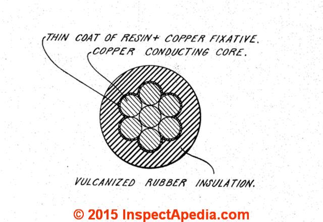
Above: coatings on the copper wire to avoid interaction with the vulcanized rubber insulation. (Meyer 1945).
Wire coatings using plating or tinning
Early wire coating efforts and later wire cladding efforts addressed the effects on copper wire of sulphur in vulcanized rubber insulation.
Ideas for producing wire of one metal covered in another by covering the copper core wire with one or more layers of other metals had been around since at least the 1920's but it is interesting to learn that early wire coating attempts started with using aluminum (or other alloys) to coat copper.
Tinning copper wire was employed to reduce the harmful interaction of rubber insulating coatings with the copper wire, including deterioration of the rubber insulation. (Meyer 1945) Note that tinning or plating coatings on wire does not produce the same coating thickness and these are different processes from copper cladding methods.
David's patent illustrated this early in the history of electrical wire production: the effort to coat the copper with aluminum (probably by plating then by tinning) was presumably to protect it from damage or from oxidation during manufacture. David had better results with a multi-layered approach of molten aluminum coating on nickel-coated copper.
The present invention relates to the manufacture of aluminum coated copper conductors, and as a consequence of my invention I have provided a conductor in which the core and coating are so well united that they will not separate, and in which the core is not injured or oxidized during the process of manufacture.
Heretofore, when attempt were made to coat copper wire with aluminum, it was found that the copper when brought into contact with molten aluminum became oxidized so that the coating would be imperfect. A tin coating on the copper also became oxidized.
Furthermore, molten aluminum alloyed with the copper to such an extent that wire being coated became reduced in diameter, its strength and current carrying capacity were impaired and it was rendered brittle.
In accordance with my invention a nonferrous foundation metal such as copper is first coated with nickel and then aluminum is applied upon the nickel. No deleterious effects are produced by molten aluminum upon nickel-coated copper. (David 1927)
Wire cladding with other metals
Attempts at coating the wire by using a metal cladding tape of a different metal were discussed along with other wire coating methods by Sprecht in 1934 who improved on earlier attempts to use silver solder or other coatings by using a metallic tape along with dies through which wire was drawn:
According to the present invention I propose to first produce a core of wire of the proper temper and diameter desired in the finished wire, and produce separately a strand of covering metal or other material in the form of a fiat ribbon-like strip, which when rolled about the core will cover it.
The core wire and covering wire are placed in juxtaposition and are first drawn through a die which bends the covering into U-form about the core, and then through other dies which close the covering over the core. (Sprecht 1937).
The inverse of copper-clad aluminum wire, that is, aluminum-clad copper wire, was still attempted in the late 1950's and updated in the early 1960's when Carlson and Rosecrans described a method of making aluminum-clad copper wire - the inverse of the final and important product discussed just below. (Carlson 1963).
This invention relates to the preparation of composite flexible wire and the like comprising a core of copper and an external sheath of aluminum metallurgically bonded thereto, and processes for producing the same. This application is a division of our U.S. patent application Serial No. 558,699, filed January 12, 1956, now Patent 2,947,069, and assigned to the same assignee.
It has long been desirable to produce wire, strip, rod and similar elongated members comprising a core of copper or copper base alloy with a relatively thin sheath of aluminum applied to the exterior surfaces thereof. It has been highly difficult to produce a satisfactory composite aluminum clad copper ,wire member heretofore.
... We have discovered processes for producing flexible, well bonded, composite elongated members comprising a copper core, a thin barrier layer of silver and a thin sheath of aluminum. By this process the composite member may be produced rapidly and economically. The composite members have proven highly satisfactory for use either as enameled wire or in other applications in the electrical industry. - (Carlson 1963)
That is, Carlson's patent described applying an an aluminum sheath as the exterior of a copper core. Significant was that the metallic sheath was "metallurgically bonded to the inner core".
[Click to enlarge any image]
Illustrated at above left is the production method for cladding one metal with another to produce a wire of one metal with a cladding of another metal. - Carlson et als. (1963).
Continuing by quotation:
When the aluminum wire and the strips enter the rolls from the plenum chamber, heat flows from the copper strips mostly to the aluminum core and some to the rolls. This rapidly brings the aluminum-copper composite to equilibrium temperature as the composite is being bonded by reduction in the solid phase.
Roll geometry copper thickness and aluminum diameter is such as to produce clad composites in the usually demanded three percentages of copper by volume, i.e. 10%, 15%, and 20%. ... The field of the invention is the manufacture of clad wire and the like as exemplified in U.S. Patents 3,220,106 and 3,220,106. - Dion (1969) This patent cites earlier work and patents by Dion (1966) and Thompson (1966, 1967).
Shift to Efforts to Apply Copper Coatings to Aluminum Wire: Copper-Clad Aluminum
Later work described by Ziemek (1974) reversed this process, placing the copper as the outer sheath and solid aluminum as the interior or main body of the wire as we discuss next. It seems likely that this reversal, placing copper on the exterior of solid-conductor aluminum electrical wiring, was in anticipation of or in response to the poor field performance of aluminum electrical wire in homes. By this time electrical wire insulation had been re-formulated from early vulcanized rubber coatings, allowing inventors to eschew the earlier concern with harmful interactions between the copper wire surface and the wire insulating material.
It was in his 1972 U.S. patent, that Gerhard Ziemek provided a succinct description of copper-clad aluminum electrical wire:
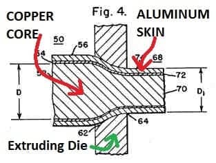
Aluminum is extruded, and the resulting core when still warm is lined with copper by deforming a copper tape around the core, welding the tape edges and drawing the resulting tube onto the core, and possibly further to obtain wire of desired diameter. (Ziemek 1972).
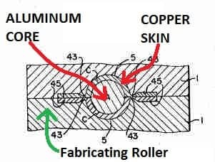
Dion (1966) and Dion and Thompson (1967) first described the successful manufacture of copper clad aluminum wire. Rolled aluminum wire is pulled through a lubricated draw to eliminate flat spots and to prepare the wire surface for a solid-bonding phase in which two copper cladding strips are added to the wire exterior.
The patent included provisions to assure that the aluminum surface was free of contaminants as were the copper strips. [Abstracted from the patent.]
Illustrated above is Dion's method of cladding aluminum wire with a layer of copper. It is significant to note that the copper thickness in this method is much greater than the typical thickness imparted by plating one metal on another. It is likely that it's that thickness that prevents a device connector screw from cutting through the copper, possibly leading to connector failures in field use.
Quoting from a later description of this process, a copper band is formed around an aluminum core wire and the single seam in the sheath material is welded without bonding of the sheath and core, care being taken that all surfaces are clean and maintained free of oxides. - Ziemek (1974)
Mr. D'Agostino relates that in 1971 as project engineer at UL, he conducted tests evaluating the performance of copper-clad aluminum conductor wiring using a number of types of copper-only receptacles (i.e. binding head screw terminals, back-wired push-in terminals, sid-wired pressure plate screw terminals) and a number of types of AL-CU pressure wire connectors.
That research, conducted under the auspices of U.L., demonstrated that performance of copper-clad wire was
- similar to that of solid copper-only wiring devices (with binding head screw terminals
- satisfactory for use in AL-CU pressure wire connectors and
- along with copper wire performed poorly, less than adequate in "back-wired push-in" wiring devices.
The findings of this research was published in a 1971 UL bulletin that was distributed / reviewed by industry and government (i.e. David Rabinov of the U.S. National Bureau of Standards).
The copper clad aluminum wire product produced by Texas Instruments is attributed by D'Agostino to John Fan (see patent citations below).
Following successful testing by D'Agostino at U.L., copper-clad aluminum electrical conductor ["copper clad electrical wire" in lay terminology] was recognized by UL/Industry and soon thereafter Nos. 10-12 AWG solid copper-clad aluminum conductor in THHN wire was used UL Listed NM Sheathed Cable. NM Cable using copper-clad aluminum electrical conductors was subsequently distributed and installed in homes in the United States (and possibly Canada) between 1972 and 1976.
Original patents on the production of copper-clad aluminum wire were awarded to a variety of parties (cited below) with early patent applications in 1956 (Carlson) and key patents (Carlson, Roserans, Westinghouse Electric) dating from 1963.
Research into the production and use of copper-clad aluminum wire continues to the present, with work by Kwon (2004) and Rhee (2004) and others on fabrication methods and by Sasaki (2010) on the metallurgy of copper-clad aluminum.
- Special thanks to Tom D'Agostino for recapping the history of aluminum electrical wiring and copper clad aluminum electrical wiring. Personal communication 5/3/2014. Mr. D'Agostino presently lives on Long Island, NY. and continues to write and research electrical hazards. He has also worked as a professional home inspector and is a member of ASHI, the American Society of Home Inspectors.
Don't confuse copper-clad wire with plated wire nor with tinned-copper plated wire nor with COALR or CU-AL Devices
Technical note: copper-clad wire or any metal "cladding" surface on wire refers to the physical application of a thin metal strip (or strips) of cladding metal that is forced-against or wrapped around the wire. This will be a thicker coating of metal skin on the wire than that typically afforded by other wire coating methods such as tin-plating.
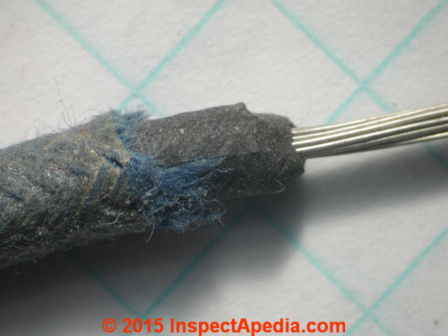
Above: tinned copper multi-strand #12 copper wire used in wiring a fluorescent light ballast in a Minnesota home constructed in the 1960's.
This discussion has moved to TINNED COPPER ELECTRICAL WIRE
Watch out: tin-plated copper wire is a completely different product that, because its conductors sport a thin plated silver colored surface, might be mistaken for unsafe aluminum wire. It is not aluminum and it is safe unless, as with any electrical wiring, it has been damaged in some manner.
Watch out: don't confuse references to copper-clad aluminum wire or tin-plated electrical wire with devices such as electrical receptacles and switches marked COALR or CU-AL. The latter two are device labels not wire types and are not a recommended repair for aluminum electrical wire. COALR and CU-AL and their field performance and safety warnings are described in more detail at ALUMINUM WIRING REPAIR COALR & CU-AL
Contact the authors
- Thomas J. D’Agostino, P.E, ASHI Certified Home Inspector, T.D’Agostino Home Inspection USA Corp.
(Islandwide Home Inspection Service)
9 Forest Court, Ste. A
Ronkonkoma, New York 11779
Office # 631-467-4663
Fax # 631-585-7048
Cell # 631-831-2076
Email:
tdagosti@aol.com
Mr. Tom D'Agostino was employed at Underwriters Laboratories from 1969 to 1996 and spent a decade and a half studying and testing the safety of aluminum electrical wiring. - Daniel Friedman can be reached via InspectApedia at CONTACT US
- Thanks to Dr. Jess Aronstein and to Tom D'Agostino, both of whom provided samples of copper-clad aluminum electrical wire that we used to prepare the photo-illustrations in this article. Dr. Jess Aronstein, protune@aol.com is a research consultant and an electrical engineer in Schenectady, NY.
Dr. Aronstein provides forensic engineering services and independent laboratory testing for various agencies. Dr. Aronstein has published widely on and has designed and conducted tests on aluminum wiring failures, Federal Pacific Stab-Lok electrical equipment, and numerous electrical products and hazards.
See ALUMINUM WIRING BIBLIOGRAPHY and FPE HAZARD ARTICLES, STUDIES and also BACK-WIRED ELECTRICAL DEVICES for examples. - Thanks to Lawrence Transue [website] an ASHI member and certified home inspector working in New Jersey. Lawrence provide the two in-situ photos of Renolds Aluminex 12/2 AL (CU-CLAD) With Ground copper-clad aluminum electrical wiring, 2018/11/18. Mr. Transue can be found on facebook at https://www.facebook.com/IntegrityInspection or contacted by Email: Lawrence@lawrencetransue.com Tel: (610) 417-0763
References for copper clad aluminum wire & related research
- Also seeReferences or Citations at the end of this or any InspectApedia.com article
- Ahmed, N. "Extrusion of copper clad aluminum wire." Journal of Mechanical Working Technology 2, no. 1 (1978): 19-32.
- Aronstein, Jesse, and Doug Lee. "Selection Criteria for Residential Aluminum Connections." In Electrical Contacts (Holm), 2012 IEEE 58th Holm Conference on, pp. 1-8. IEEE, 2012.
- Aronstein, Jesse. "Analysis of field failures of aluminum-copper pigtail splices made with twist-on connectors." In Electrical Contacts, 1999. Proceedings of the Forty-Fifth IEEE Holm Conference on, pp. 87-93. IEEE, 1999.
- Aronstein, J. "Evaluation of receptacle connections and contacts." In Electrical Contacts, 1993., Proceedings of the Thirty-Ninth IEEE Holm Conference on, pp. 253-260. IEEE, 1993.
- Aronstein, J. E. S. S. E., and THOMAS K. Hare. "Evaluation and analytical electron microscopy investigation of a plated aluminum wire for branch circuit applications." Components, Hybrids, and Manufacturing Technology, IEEE Transactions on 11, no. 2 (1988): 218-226.
- Austin, David, John Cabral, and Joseph Longever. "Copper clad aluminum strips and a process for making copper clad aluminum strips." (2002)
- Bahre, Werner, Karl H. Stobaus, and Gerhard Ziemek. "Cold drawing, annealing." U.S. Patent 4,134,528, issued January 16, 1979.
- Carlson, Charles L., Rosecrans, Irwin and Stanley A., assignors to Westinghouse Electric Corporation, Pittsburgh PA, Original application 12 Jan. 1956, Patent No. 2,947,069 dated 2 Aug. 1960, divided and this application 9 June 1960. U.S. Patent No. 3,096,577, 9 July 1963.
- David, Basch. "Composite electric conductor." U.S. Patent 1,637,033, issued July 26, 1927.
Excerpt:
The present invention relates to the manufacture of aluminum coated copper conduc tors, and as a consequence of my invention I have provided a conductor in which the core and coating are so well united that they will not separate, and in which the core is not injured or oxidized during the process of manufacture.
Heretofore, when attempt were made to coat copper wire with aluiinum, it was found that the copper when brought into contact with molten aluminum became oxidized so that the coating would be imperfect. A tin coating on the copper also became oxidized. Furthermore, molten aluminum alloyed with the copper to such an extent that wire being coated became reduced in diameter, its strength and current carrying capacity were impaired and it was rendered brittle.
In accordance with my invention a nonferrous foundation metal such as copper is first coated with nickel and then aluminum is applied upon the nickel. No deleterious effects are produced by molten aluminum upon nickel-coated copper. - D’Agostino, Thomas. J. "Recognition of copper-clad aluminum conductor for use in terminals suitable for copper conductor." Underwriters Laboratories, Inc., Melville, NY, Bulletin, Subjects 4, 44,83,486,498, 719 (April 2, 1971).
- D'Agostino, T.J., personal communication with D Friedman by telephone & email, May 2014.
- Dion, Paul A., & Carr, Martin W., assignors to Texas Instruments, "Manufacture of Clad Wire and the Like", United States Patent No. 3,455,016, 15 July 1969.
- Fan, John CC. "Cermet film selective black absorber." U.S. Patent 4,312,915, issued January 26, 1982.
- Kwon, Hyouk Chon, Taek Kyun Jung, Sung Chul Lim, and Mok Soon Kim. "Fabrication of copper clad aluminum wire (CCAW) by indirect extrusion and drawing." In Materials Science Forum, vol. 449, pp. 317-320. 2004.
- Lin, Mei-mei. "Manufacturing process for making copper-plated aluminum wire and the product thereof." U.S. Patent 4,919,769, issued April 24, 1990.
- Meyer, Albert W., "Rubber covered copper article." U.S. Patent 2,379,978, issued July 10, 1945.
Excerpt:
This invention relates to rubber covered copper articles, and more particularly latex-rubber insulated electrical conductors having a metallic copper conducting core whereby to inhibit or prevent the discoloration of the rubber by the copper.
While the invention is not limited to wire, it is particularly important in that field. Rubber insulation on copper wire rapidly decreases in its tensile strength and other physical properties, and in the case of light colored stock, the rubber insulation is soon darkened.
The copper has a harmful effect on rubber; it causes reduction in tensile strength, modulus, and abrasion resistance, and eventually may produce a sticky mass. Tinning of .the copper before the rubber covering is applied reduces the harmful effects but is not completely effective since the copper can migrate through the tin into the rubber. - National Electrical Code, U.S., For aluminum and copper-clad aluminum conductors, see NEC Section 310.15.
- Perrard, Wayne. "TECHNICAL PAPERS-Strategies for optimizing cable design and performance through the use of bimetallic wire-Used separately or in combination, copper-clad aluminum wire and copper-clad steel wire." Wire Journal International 34, no. 7 (2001): 154-159.
- Polleys, William V. "Copper Clad Aluminum Wire." Wire Ind., 1974 Yearbook, 188, 191. (1974).
- Rhee, K. Y., W. Y. Han, H. J. Park, and S. S. Kim. "Fabrication of aluminum/copper clad composite using hot hydrostatic extrusion process and its material characteristics." Materials Science and Engineering: A 384, no. 1 (2004): 70-76.
- Ruemmler, Waldemar P. "Low tin content, durable, tinned copper conductor." U.S. Patent 2,742,687, issued April 24, 1956.
Claim excerpt:
This invention relates to coatings for electric conductors and more particularly to substitute coatings for tin on copper wire. - Sasaki, T. T., R. A. Morris, G. B. Thompson, Y. Syarif, and D. Fox. "Formation of ultra-fine copper grains in copper-clad aluminum wire." Scripta Materialia 63, no. 5 (2010): 488-491.
- Shea, J., and Xin Zhou. "Material effect on glowing contact properties." In Electrical contacts-2007, the 53rd ieee holm conference on, pp. 90-97. IEEE, 2007.
- Snyder, Clermont J., and Willis G. Maclelland. "Method of tinning copper wire." U.S. Patent 2,515,022, issued July 11, 1950.
Excerpt:
This invention relates to the art of tinning metals, and has for its principal object to provide an improved method of forming on metal articles, such as wires, thin, substantially uniform, continuous, adherent metallic coating. This application is a continuation-in-part of our copending application, Serial No. 462,002, filed October 14, 1942, now abandoned.
... The tinning metal heretofore used for tinning these and other metal articles has been either commercially pure tin, or a lead-tin alloy containing a high percentage of tin. In recent years much effort has been directed to finding a suitable tinning alloy containing only a small proportion of tin, or none at all, but to a large extent only indifferent success has heretofore resulted from these efforts. For example, lead base alloys containing no tin have been proposed as substitutes for tin for this purpose, but such alloys for the most part do not adhere well to wire or other metal particles.. - Specht, Harry G., "Method of producing covered wire." U.S. Patent 2,088,446, issued July 27, 1937. Assigned to Eastwood Nealley Corp.
Excerpt:
Claim. The present invention relates to an improvement in covered wire and method of producing the same, an object being to produce a wire comprising a core of metal or other material and a covering of a different material than the core, in a manner whereby the desired characteristics of the covering material may be provided without respect to the characteristics of the core, as distinguished from previous methods of producing covered wire wherein the limitations of the materials of the core and covering had to be considered and compromised for, with the result that it was not always possible to obtain all of the desired characteristics in the core and covering.
This was particularly true of small diameter covered wire such as silver solder covered wire, and other alloy coatings on hard and soft cores, as used in the formation of soldered seams in wire mesh fabric, and in the jewelry and other trades.
In making solder covered wires or in coating a core of one material with the shell of another material the methods heretofore employed consisted in rolling and drawing out a billet which had the covering material bonded about the core.
One well-known process consists in turning up a core of material from one inch to six inches in diameter, placing this in a graphite or other suitable mold, and pouring the melted .30 covering material about the core and allowing it to solidify, binding the covering material to the core.
The billet of combined metal is then taken from the mold and through a rolling, annealing and drawing process is reduced to the desired wire size. Another method consists in shrinking around a core a shell or tube of suitable bonding material, as for instance hard or soft solder, and then shrinking on top of this a shell or tube of the desired covering material.
This three-piece billet is then heated to a temperature where the middle shell of bonding material will melt and form an intimate union between the cone and the outside shell. billet is then rolled and annealed and drawn into wire of the desired diameter. These methods are used both for producing very small diameter covered wire, and also in the making of copper and brass clad wire, and lead coated and other types of wires used in cable and electrical power lines.
Obviously this continual rolling, annealing and drawing process is expensive and complicated, and has the further disadvantage that it does not permit of covering the core with materials that have a lower melting temperature than the annealing tempeature of the core. This is because due to the rolling and drawing operations the material hardens and before it can be further processed, it must be annealed.
If the melting temperature of the outside shell is below the annealing temperature of the core, the material cannot be annealed, and for this reason it has been impracticable to produce solder covered wire in which the solder had a relatively low melting point and in which the proper malleability and 0 ductility were maintained.
It is also not possible to obtain uniformity in the covered wire produced by these methods, with the result that the covering may have thin and thick spots, the core is apt to be out of center, and the wire 15 is not of uniform cross-section.
According to the present invention I propose to first produce a core of wire of the proper temper and diameter desired in the finished wire, and produce separately a strand of covering metal or other material in the form of a fiat ribbon-like strip, which when rolled about the core will cover it.
The core wire and covering wire are placed in juxtaposition and are first drawn through a die which bends the covering into U-form about the core, and then through other dies which close the covering over the core.
In the case of a metal covering the seam of the covering may be fused, soldered, brazed or otherwise joined to produce a solid covering, and/or the covering may be bonded at its inner surface to the core, as by beating to a proper fusing temperature, or by interposing an intermediate bonding layer.
By this process I can cover any core material with a shell of any covering material, regardless of the melting temperature of either the core or the shell, and the core will always be perfectly central and of uniform cross-section. - "Equipment Wiring Terminals for Use with Aluminum and/or Copper Conductors - UL 486E", Underwriter Laboratory Standards, Retrieved 5/4/2014, original source: http://ulstandardsinfonet.ul.com/scopes/0486e.html [Abstract only]
- Wolfram, Klebl, Schatz Friedrich, Staschewski Harry, and Ziemek Gerhard. "Method and apparatus for making copper clad steel wire." U.S. Patent 3,894,675, issued July 15, 1975.
- Yamaguchi, Tetsuo, Teruyuki Takayama, and Masao Hiderita. "METHOD OF PRODUCING COPPER CLAD ALUMINUM WIRE." U.S. Patent 3,854,193, issued December 17, 1974.
- Ziemek, Gerhard. "Heating steel wire, joining metal bands to surface by rolling under reducing gas, reducing cross-section, heating copper wire, joining to first element." U.S. Patent 5,924,194, issued July 20, 1999.
- Ziemek, Gerhard, and Michael Meyer. "Method for producing a sector conductor for electric power cables." U.S. Patent 5,732,875, issued March 31, 1998.
- Ziemek, Gerhard B., Izyaslav G. Peshkov, Grigorij Svalov, Victor E. Sytnikov, and Valerij A. Mitrochin. "Flexible, high temperature superconductive cables." U.S. Patent 5,143,897, issued September 1, 1992.
- Ziemek, Gerhard. "Method for producing copper-clad aluminum wire." U.S. Patent RE28,526, issued August 26, 1975.
Note: The abstract text for this patent is garbled so we include below excerpts from the body of the patent description:
OBJECTS OF THE INVENTION An object of the present invention is to provide an improved method of producing copper-clad aluminum wire. Another object of the present invention is to provide a method of producing copper-clad aluminum wire which avoids the creation of any embrittling phases in the product. A further object of the present invention is to provide a method of producing copper-clad aluminum wire wherein tearing of the copper sheath during processing is avoided.
A still further object of the present invention is to provide a method of producing copperclad aluminum wire which does not require preheating of the work pieces. Various other objects and advantages of the invention will become clear from the following description of embodiments thereof, and the novel features will be particularly pointed out in connection with the up pended claims.
METHOD FOR PRODUCING COPPER-CLAD ALUMINUM WIRE Matter enclosed in heavy brackets 1 appears in the original patent but forms no part of this reissue specification; matter printed in italics indicates the additions made by reissue.
BACKGROUND OF THE INVENTION
1. Field of the Invention The present invention relates generally to the continuous production of clad wire and, more particularly, it relates to the production of wire comprising a thin sheath of copper clad onto an aluminum core. Such products combine the light weight and economy of aluminum with the outstanding electrical properties of copper.
2. Prior Art Originally, the production of composite wire I stands I strands having a core of one metal and a sheath of another metal was carried out by merely electroplating a wire, or by hot melt dipping. Such methods were unsatisfactory because of either the lack of prod uct uniformity or by not being adapted for continuous production on high speed automatic equipment.
More recently, clad wire products have been produced by a method known as roll bonding. One supply reel holds the core wire and two other reels hold narrow strips of the cladding meta]. All three pieces are first fed through appropriate cleaning stations, where gross contaminants and oxide films are removed, it being well recognized that any sort of impurity will prevent good bonding. Between the cleaning and bonding stations, re-oxidation is prevented by maintaining a protective atmosphere, either inert or reducing, around the workpieces.
At the same time, the workpieces are heated to proper bonding temperatures, which may be the same for sheath and core metals or may be different. The heated workpieces, with the core wire disposed between the two flat sheath strips, are then fed into the nip of a pair of grooved rolls, which bend the sheath strips around the core, bonding one to the other and bonding the sheath pieces to each other at diametrically opposed seams.
Means are provided to shear off excess sheath material at the seams, and further rolling may be provided to bring the material to desired size and improve the bond. Variations, including the use of a single strip of sheath material bent into tubular form around the core, are known.
Typical of the many US. patents describing roll bonding processes are US Pat. No. 3,220,107 of K. B. Clark, and US. Pat. No. 3,320,666 of P. A. Dion I More recently, somewhat simpler methods have been developed for cladding wire, and US. Pat. No. 3,562,899 describes one such method. The core wire is initially straightened after it comes off the supply reel, and the sheath and core are cleaned, rinsed and dried in continuous equipment. A series of rolls form the sheath around the core, with some slight clearance
A welder then welds the seam, care being taken that the weld not penetrate the entire sheath, which could alter the metallurgical condition of the core. Sizing rolls bring the wire to its final dimensions, and it is either coiled or cut into discrete lengths.
It is noted that many workers in the cladding field recognize the utility of heat treatments subsequent to cladding, both to overcome the effects of mechanical deformation (i.e., work hardening) and to improve the quality of the bond. Typical of these is the US patent of Boessenkool, US. Pat. No. 2,753,623 - Ziemek, Gerhard, assigned to Kabel-und Metallwerke Gutehoffnungshuette AG, Hannover Germany, Issued 5 June 1974, as a reissue of U.S. Patent No. 3,800,405 2 April 1974
Abstract: A copper band is formed around an aluminum core wire and the single seam in the sheath material is welded without bonding of the sheath and core, care being taken that all surfaces are clean and maintained free of oxides.
The copper tube is reduced to the diameter of the aluminum core. This composite wire is then passed through a plurality of drawing dies which reduce the diameter of the wire, preferably at least 50 percent, care being taken to prevent the copper sheath from tearing.
The drawing operation produces, depending on the reduction rate, an initial or a complete bond between the core and sheath.
Subsequently, the clad wire is either subjected to a limited diffusion heat treatment, conditions of the heat treatment being controlled to produce a complete and flawless bond between the sheath and core but, at the same time, avoiding the formation of any CuAl2, a phase which is brittle or is annealed to get the required grade.
Generally, the diffusion layer on either side of the sheath-core interface is limited to about 10 μ, preferably less. - Ziemek, Gerhard, "Method for Making Copper Plated Aluminum Wires." U.S. Patent 3,648,356, issued March 14, 1972.
Abstract:
Aluminum is extruded, and the resulting core when still warm is lined with copper by deforming a copper tape around the core, welding the tape edges and drawing the resulting tube onto the core, and possibly further to obtain wire of desired diameter.
Excerpts:
METHOD FOR MAKING COPPER PLATED ALUMINUM WIRES The invention relates to a method of making so-called copper-clad, aluminum wires comprising a wire core element of aluminum with a coating or lining of copper.
Copper-clad aluminum wires have the particular advantage of comparably low specific weight, and they combine economy resulting from use of inexpensive aluminum with good electric properties of copper. For making such wires, it is known, for example, to provide a copper tube, to fill the same with aluminum, and to draw the resulting structure in a manner known per se, so that the diameter is reduced to the desired dimension. In order to avoid formation of cavities which would be detrimental to the homogenity of the resulting wire, it is necessary that the pipes used are of limited length.
Therefore, continuous manufacturing of copper-clad wires in this manner is not possible. Furthermore, it was found that at temperatures equal to or above the melting temperature of the aluminum, the diffusion of copper into aluminum is considerable. The resulting diffusion layer has harder consistency so that the subsequent drawing requires particular precautions.
In accordance with another method it is known to provide an aluminum wire and two copper tapes of predetermined length. The copper tapes are deformed around the aluminum wire so that the wires become enclosed in two half cylinders, running in longitudinal direction parallel to each other and to the aluminum wire.
Subsequently, the edges of the two half cylinder-copper tapes are welded to form a sleeve. The thus formed copper sleeve is then applied to and drawn onto the aluminum wire core to obtain a smaller diameter. In addition, it has been suggested to provide an aluminum wire core, to continuously deform a copper tape to as to establish a sleeve, and to weld adjoining edges of such tape. Subsequently, the sleeve diameter is reduced by drawing, at least down to the diameter of the aluminum wire.
The present invention proceeds in a different manner for manufacturing copper lined or clad aluminum wire. The copper-plating, lining or coating is also to be made from a deformed copper tape which is being welded to provide a tube or sleeve around the aluminum core. However, in accordance with the present invention, an extrusion press is provided for producing a continuously running and extractable aluminum string to serve as aluminum core.
As the extruded aluminum core is still warm, it is clad with a copper sleeve, there being a tape running longitudinally into the production line, and being deformed to establish a tubular sleeve around the aluminum string. 'I'hat copper tape or sleeve is welded along its edges and subsequently the copper tube is reduced in diameter by drawing it onto the aluminum wire.
The aluminum core with copper tube applied may subsequently be reduced further in diameter to obtain the desired dimensions of the wire of the wire to be produced. This way, it is possible to provide copper-clad aluminum wire in a single working step though serially operating stages may be provided.
A faultless, mechanically firm connection is established between the copper coat and the aluminum core if one proceeds in accordance with the teaching of this invention. During the production of copper-clad wires in accordance with known methods an oxide layer forms usually on the aluminum core which layer is partially destroyed only during the diameter reduction step or has to be removed in a separate step.
In order to impede or to inhibit formation of an oxide layer it is of particular advantage to extract the aluminum core from the press in a protective gas environment, and preferably the subsequent coating of the core by lining it with copper tape is likewise carried out in a protective gas atmosphere. In other words, the uncovered aluminum core, from the point where leaving the extrusion press up to the point where the copper lining is closed, should traverse a protective gas atmosphere, that part of the production line being enclosed accordingly.
...
Continue reading at ALUMINUM WIRING IDENTIFICATION or select a topic from the closely-related articles below, or see the complete ARTICLE INDEX.
Or see these
Recommended Articles
- ALUMINUM WIRING HAZARDS & REPAIRS - home
- ALUMINUM WIRE GROUNDS
- ALUMINUM WIRING IDENTIFICATION
- ALUMINUM WIRING SAFETY ASSESSMENT - CPSC
- ALUMINUM WIRIING SUMMARY free to copy page
- COPPER-CLAD ALUMINUM WIRE
- SAFETY for ELECTRICAL INSPECTORS
Suggested citation for this web page
COPPER-CLAD ALUMINUM WIRE at InspectApedia.com - online encyclopedia of building & environmental inspection, testing, diagnosis, repair, & problem prevention advice.
Or see this
INDEX to RELATED ARTICLES: ARTICLE INDEX to ELECTRICAL INSPECTION & TESTING
Or use the SEARCH BOX found below to Ask a Question or Search InspectApedia
Ask a Question or Search InspectApedia
Try the search box just below, or if you prefer, post a question or comment in the Comments box below and we will respond promptly.
Search the InspectApedia website
Note: appearance of your Comment below may be delayed: if your comment contains an image, photograph, web link, or text that looks to the software as if it might be a web link, your posting will appear after it has been approved by a moderator. Apologies for the delay.
Only one image can be added per comment but you can post as many comments, and therefore images, as you like.
You will not receive a notification when a response to your question has been posted.
Please bookmark this page to make it easy for you to check back for our response.
IF above you see "Comment Form is loading comments..." then COMMENT BOX - countable.ca / bawkbox.com IS NOT WORKING.
In any case you are welcome to send an email directly to us at InspectApedia.com at editor@inspectApedia.com
We'll reply to you directly. Please help us help you by noting, in your email, the URL of the InspectApedia page where you wanted to comment.
Citations & References
In addition to any citations in the article above, a full list is available on request.
- [1] J. Aronstein, "Fire Due to Overheating Aluminum Wired Branch Circuit Connections", Electrical Safety Conference: Electrical Fires; Cause, Prevention, Investigation. University of Wisconsin, Extension, Madison WI, April 7, 1981.
- [2] "National Controlled Study of Relative Risk of Overheating of Aluminum Compared With Copper Wired Electrical Receptacles in Home and Laboratory", Executive Summary. Prepared for U.S. Consumer Product Safety Commission. Report #F-C4812-01, Franklin Research Center, Philadelphia, PA, April 20, 1979.
- [3] R. Newman and W.H. King, Jr., "Pilot Study of Branch Wiring Systems in Montgomery County, Maryland", U.S. Consumer Product Safety Commission, Sept., 1977.
- [4] J. Aronstein, "Summary Report, Study of Overheating of Aluminum-Wired Electrical Receptacles in Scarborough, Toronto, Homes", Wright-Malta Corp., Ballston Spa, NY, January 11, 1982.
- [5] J. Aronstein, "Test of 'Old Technology' Aluminum Wire With Twist-On Connectors", Project Report CPSC-C-79-0079, Task II, For U.S. Consumer Product Safety Commission, Wright-Malta Corp., Ballston Spa, NY, Feb. 24, 1981.
- [6] J. Aronstein, "Overheating Failures of Presently-Listed Aluminum-Wired Connection Combinations Within Rated Service Conditions", Wright-Malta Corp., Ballston Spa, NY, November 23, 1981.
- [7] "The Trouble With Aluminum Wiring", Consumer Reports, January, 1981, p. 42.
- [8] R.L. Hicks, "Pigtail Splicing Connections for Baseboard Heaters and Similar Cyclic Loads", Ontario Hydro Research Division, Report #78-235-K, May 17, 1978, p. 3, (Table 1).
- [9] "Aluminum Building Wire Installation Manual and Design Guide", The Aluminum Association, Inc., Washington, DC. (p. 12 in 1978 Edition).
- [10] J. Aronstein and T.K. Hare, "Evaluation and Analytical Electron Microscopy Investigation of a Plated Aluminum Wire for Branch Circuit Applications", IEEE Transactions: Components, Hybrids, and Mfg. Tech., V. CHMT-11 No. 2, June 1988.
- [11] J. Aronstein, "Evaluation of a Twist-On Connector for Aluminum Wire", Transactions, 43rd IEEE Holm Conference on Electrical Contacts, Philadelphia, 1997
- [12] J. Aronstein, "Analysis of Field Failures of Aluminum-Copper Pigtail Splices Made With Twist-on Connectors", Transactions, 45th IEEE Holm Conference on Electrical Contacts, Pittsburgh, PA, 1999
Reducing the Fire Hazard in Aluminum-Wired Homes Sept. 12, 2000 p. 17
6. BIBLIOGRAPHY: TECHNICAL REPORTS, CONNECTOR PERFORMANCE WITH ALUMINUM WIRE
R. Newman, "Hazard Analysis of Aluminum Wiring", April, 1975, U.S. CPSC, NIIC-0600-75-H006
M. Leger, "Metallurgical Analysis of Failed CO/ALR Devices", Ontario Hydro, #78-54-K, Ontario, Canada, February, 1978
J. Aronstein and W.E. Campbell, "Failure and Overheating of Aluminum-Wired Twist-on Connections", IEEE Trans. Components, Hybrids, and Mfg. Tech., V. CHMT-5 No.1, March 1982
J. Aronstein, "Tests of 'Old Technology' Aluminum Wire at Special Crimp Type Compression Connectors" (Amp COPALUM), Wright-Malta Corp. Project Report CPSC-C-79-0079 Task III, U.S. Consumer Product Safety Commission, Washington, DC, Feb. 5, 1983
J. Aronstein, "Tests of 'Old Technology' Aluminum Wire", Wright-Malta Corp. Project Report CPSC-C-81-1418, U.S. Consumer Product Safety Commission, Washington, DC, Feb. 10, 1983
J. Aronstein and W.E. Campbell, "Overheating Failures of Aluminum-Wired Special Service Connectors", IEEE Trans. Components, Hybrids, and Mfg. Tech., V. CHMT-6 No. 1, Mar. 1983
J. Aronstein and W.E. Campbell, "The Influence of Corrosion Inhibitor and Surface Abrasion on the Failure of Aluminum-Wired Twist-On Connections", IEEE Trans. Components, Hybrids, and Mfg. Tech., V. CHMT-7 No. 1, Mar. 1984
J. Aronstein and W.E. Campbell, "Evaluation of an Aluminum Conductor Material for Branch Circuit Applications", IEEE Trans. Components, Hybrids, and Mfg. Tech., V. CHMT-8 No. 1, Mar. 1985
R. Schubert, "Erratic Behavior of Al/Al Wire Junctions", Electrical Contacts - 1986, Proceedings of the 32nd IEEE Holm Conference on Electrical Contacts, Boston, 1986.
[Following added 3/5/2003 at Dr. Aronstein's suggestion, not part of original article -- DJF]
J. Aronstein, "Evaluation of a Twist-on Connector for Aluminum Wire", Forty-Third IEEE Holm Conference on Electrical Contacts, Jan 1997, 0-7803-3968-1/97. [This article describes the Ideal Industries Ideal#65 purple "Twister" twist-on connector marketed as a repair/retrofit for residential aluminum wiring .--DJF]
Abstract: A new type of twist-on splicing component for use with aluminum and copper wire combinations is tested to determine initial resistance, performance in a zero-current environment test, performance in a heat-cycle test, and portion of current carried by the connector's steel spring.
The splices tested consist of two aluminum wires and one copper wire. The aluminum wire samples used for the test are of the types actually installed in aluminum-wired homes. Initial resistance is found to be relatively high, and there is a significant sample-to-sample variation.
This reflects failure to consistently establish low-resistance wire-to-wire contact Through the insulating oxide film on the wire. Results of the environmental and heat-cycle tests show deterioration of a significant portion of the samples. The splices made with this connector are also found to be sensitive to mechanical disturbance, such as applied in normal installation when the completed splice is pushed back in to the junction box.
Based on the test results, it is concluded that this connector has not overcome the fundamental deficiency of twist-on connectors for use with aluminum wire applications. Keywords: aluminum wire, connectors, twist-on connectors, environmental test, heat-cycle test.
 The Aluminum Wiring Information Website Aluminum Wiring Hazards and Repairs: in-depth info, photos, documents. Main Page.
- The Aluminum Electrical Wiring Hazard Explained (in the document you are presently viewing)ALUMINUM WIRE REPAIR METHODS to reduce risk in buildings with Aluminum Electrical Wiring - Overview of Acceptable Repair Practices (in the document you are presently viewing)Aluminum Wire Repair Method Details - "How to" details, how to identify, COPALUM repair, alternative repairs, history, products, research, source of special AMP TYCO COPALUM connectors & COPALUM Electricians (in the document you are presently viewing)COPALUM Electricians: Sources of TYCO COPALUM -Certified/Trained Aluminum Wire Repair Services (in the document you are presently viewing)
- ALUMINUM WIRING REPAIR, Other Products, Ideal 65 Purple Twister (not recommended), & other Aluminum Wire Products/Articles (in the document you are presently viewing)
- The Aluminum Wiring Bibliography: extensive resources on Aluminum Wiring
- Aluminum Wire Failure Reports & Photos: Real life aluminum wiring field failure reports can be seen at InspectAPedia.com/aluminum/Aluminum_Wiring_Failure_Reports.php
- Reducing the Fire Hazards in Aluminum-Wired Homes, Jess Aronstein, Ph.D., This document answers most technical questions about the hazards and remedies of aluminum electrical wiring. Some of the sections of this very thorough document are listed below:
- Fire Hazards With Aluminum to Copper Twist-on Connectors & Acceptable Aluminum Wiring Repair Practices Color Photos, Current Issues. 9/28/95 CPSC Meeting Minutes
- "Is YOUR Aluminum Wiring Safe?" article discussing safety claims made by some people without looking at the wiring, J. Aronstein, 11/21/95
- REPAIRING ALUMINUM WIRING, US CPSC Pub. No. 516 U.S. Consumer Product Safety Commission Publication available online
- Our recommended books about building & mechanical systems design, inspection, problem diagnosis, and repair, and about indoor environment and IAQ testing, diagnosis, and cleanup are at the InspectAPedia Bookstore. Also see our Book Reviews - InspectAPedia.
- In addition to citations & references found in this article, see the research citations given at the end of the related articles found at our suggested
CONTINUE READING or RECOMMENDED ARTICLES.
- Carson, Dunlop & Associates Ltd., 120 Carlton Street Suite 407, Toronto ON M5A 4K2. Tel: (416) 964-9415 1-800-268-7070 Email: info@carsondunlop.com. Alan Carson is a past president of ASHI, the American Society of Home Inspectors.
Thanks to Alan Carson and Bob Dunlop, for permission for InspectAPedia to use text excerpts from The HOME REFERENCE BOOK - the Encyclopedia of Homes and to use illustrations from The ILLUSTRATED HOME .
Carson Dunlop Associates provides extensive home inspection education and report writing material. In gratitude we provide links to tsome Carson Dunlop Associates products and services.


