 Balancing Heating & Air Conditioning Air Flow
Fix duct mistakes or damage that reduce air delivery
- POST a QUESTION or COMMENT about balancing air delivery or air supply in duct systems for heating and air conditioning
Heating & air conditioning HVAC ductwork air flow balancing:
This building air supply ductwork diagnosis and repair article describes proper (and improper) balancing of heating & air Conditioning duct air flow in residential buildings and in commercial office space including high-rise buildings.
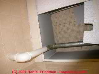
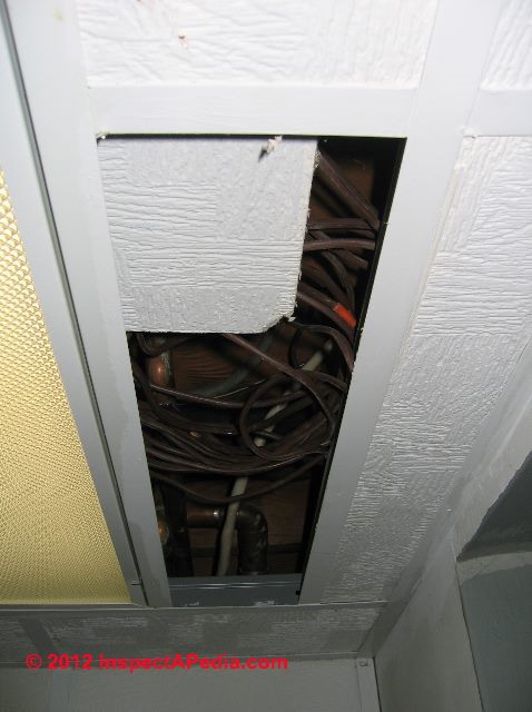
Our page top photo shows how individual office occupants who are too hot or too cold can foul up carefully balanced air distribution in a building. Just push over a section of suspended ceiling.
InspectAPedia tolerates no conflicts of interest. We have no relationship with advertisers, products, or services discussed at this website.
- Daniel Friedman, Publisher/Editor/Author - See WHO ARE WE?
Balance Air Ducts for Proper Warm or Cool Air Delivery
 HVAC duct air flow balance means that we have adjusted the flow through the air duct system such that we get the desired quantity of cool or warm air in all of a building's occupied spaces.
If the duct air flow system is out of balance you will find that when heating, some rooms are not warm enough while others are too cool. While in cooling or air conditioning mode you'll find similarly that some rooms are not cool enough while others are too warm.
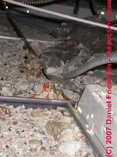
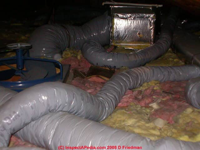
Shown in our photo: rather excessive loops of flex duct in an attic have the effect of significant air flow reduction.
When ductwork runs like a crazy twisting worm all through an attic its unnecessary length and extra sinuous bends and crips can seriously block air flow to some building areas.
Generally we want to keep ductwork as short and direct as possible.
Article Contents:
Look for indications that the system has not been balanced for optimum air flow:
- Uneven temperatures throughout the air conditioned space, room to room, or within rooms, when the system is operating in either heating or cooling mode
- All registers are open but airflow varies widely from register to register
- In cooling mode, uneven condensate production (maybe)
- Also see ZONE DAMPER CONTROLS where we explain the use of manual or automatic duct dampers for adjusting and balancing building airflow through its HVAC duct system
You may want your service person to review air flow in different rooms, to add manual balancing dampers in the duct system (and show you where they are located and mark on the duct just where the balancing damper levers are normally set.
Air conditioning cool air balancing in offices & commercial spaces or in homes with long HVAC duct runs
Location of Air Supply and Air Return Registers Causing Un-Balanced or Poor HVAC Air Flow
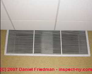
The photographs above show both supply and return ceiling registers in a commercial office space. In this case they are located too close together. The second photograph (above right) shows that a ceiling tile has been removed from a suspended ceiling over an office which uses the ceiling cavity as a common return air plenum.
While this may produce more airflow in the office where this suspended ceiling tile was removed, it has unbalanced the entire air conditioning system for the rest of the offices in the building.
Many commercial spaces and offices are cooled (and sometimes heated as well) by an air handler which delivers supply air to each office area by flex duct connected to ceiling registers.
Return air is passed back to the air handler through the large common space above a suspended ceiling over the occupied space.
Special vents either around the supply registers or placed separately are intended to pass return air to the common ceiling space, and their location and adjustment are important to provide balanced airflow in the work space.
Single Return Air Inlet & Un-Balanced Cooling or Heating Airflow
Use of a single return air location invites un-balanced air flow delivery into various rooms in a building, especially if room doors are left shut and there is no provision for air movement out of closed rooms to the central return register.
In addition, distance to the central return air register, obstructions, or circuitous routing through hallways or even among different floors in a building all argue that a single central return air register can contribute to an air-starved air handler or uneven air delivery to the conditioned spaces.
See RETURN AIR REGISTERS & DUCTS
and
UNDERSIZED RETURN DUCTS for details.
RETURN AIR, INCREASE may also be helpful.
Poor Heating or Cooling Air Flow & Debris & Contaminants in Ceilings Used as Return Plenums Risk Entrainment in Building HVAC Airflow
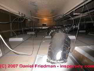
This photograph shows a common ceiling plenum over a commercial office space in a Manhattan high rise building. Notice the considerable amount of debris atop the ceiling tiles?
All of the office conditioned air moves through this area, risking additional levels of irritating or harmful particles, particularly if the debris contains asbestos fragments or lead paint chips. (In this particular case tests showed that this was not the case.)
Here are some common concerns or defects in commercial installations that use this design:
- Missing ceiling tiles: People in individual offices subvert the system by seeking more or less cool air by removing suspended ceiling tiles.
These un-planned openings make it impossible for the system to be properly balanced. - Common return air plenum Use of the ceiling space as a giant return plenum above the work area means that any debris, mold (perhaps from roof leaks), fiberglass, asbestos, or other problematic particles that are in this space are readily circulated through the building air
Openings that Subvert Proper HVAC Duct Airflow
These photos show a common ceiling return air plenum over commercial offices. In the first or left hand photo, notice that rectangular opening in the distance?
The second photo (below) is a close-up showing a big surprise: the ceiling area used as return air plenum for an office suite is wide open to the rest of the building ceilings on the same floor.
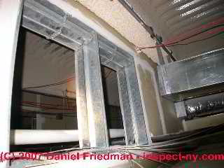
Openings had been left open between the office space and the top floor hallway and also between the hallway and other office spaces in the building, so that particles, leak-related mold, or other irritating particles developing over any office will be shared among all of the tenants on this building floor.
Watch out: unanticipated or improper openings between building areas may also be a fire hazard, contributing to the rapid spread of fire from one building area to another.
See FIRE & SMOKE DAMPERS, AUTOMATIC.
Also see UNSAFE DUCT OPENINGS.
Missing or incomplete ceiling partitioning
in large commercial buildings may mix air (and odors or contaminants) from multiple offices or building use areas, redistributing these un-wanted odors or particles to other building areas.
One of our clients who maintained a law office in a strip mall complained of chemical odors which were traced to a beauty parlor located at the extreme other end of the building.
Open windows,
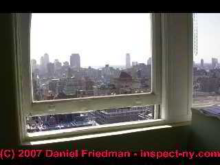
especially in a tall office building such as shown by this photograph, cause a tremendous up-draft through the building, moving particles, gases, or other potential IAQ concerns up through the building.
In this instance (above left) the office occupants on the 18th floor of this Manhattan office opened their windows and also their office entry door to try to cool off their offices because they were unable to turn off the building heating radiators.
See AIR MOVEMENT in BUILDINGS for details.
Other Causes of & Cures for Un-Balanced or Poor Air Flow Through Commecial or Long Residential HVAC Duct Runs
In addition to the HVAC air duct flow balancing problems & recommendations discussed above, consider these possible causes of inadequate cool air or warm air deliver to some building areas:
- Air register locations
poorly chosen: placing supply and return air registers too close to one another, or placing them too high or too low on a wall or through a floor behind a couch or under a rug are examples of mistakes that can leave some building areas without good cooling or heating.
See LOCATION OF REGISTERS & DUCTS - HVAC Duct leaks
leaky ducts or even open duct connections, especially un-discovered in hidden areas, can completely subvert balanced cool or warm air flow distribution in a building even if the original duct layout and design were well done.
See LEAKY DUCT CONNECTIONS - HVAC Duct layout problems
Un-balanced HVAC air flow or cool air or warm air delivery due to differences in HVAC duct length, diameter, bends, restrictions may fail to properly balance air flow across a long flat building, between building floors, or where ducts have to make tortous passage from one building area to annother;
See DUCT ROUTING & SUPPORT
Also see DUCT SYSTEM DESIGN SIZE & DEFECTS - home - HVAC Duct Size, Materials, Cleanliness
all also affect air flow. Since these conditions can vary among various airduct segments in a building, obstructions will certainly create duct balancing problems that can take some trouble (and careful duct inspection) to resolve. - Inadequate return air or tight rooms
if a building uses centralized return air inlets to the HVAC system then remote building areas may lack adequate air flow because of inadequate return air flow out of that building area back to the system air handler;
for example closing the door to a room that has no in-room return duct inlets may substantially reduce the flow of conditioned air into that room.
See RETURN AIR REGISTERS & DUCTS and
also see UNDERSIZED RETURN DUCTS. - Stuck or not-working HVAC Duct Dampers, Booster Fans:
check to make sure that duct balancing dampers have not been manually left in the wrong position (shut, open when should be partly closed, etc) and that automatic devices such as duct balancing dampers and duct booster fans and their controls are in fact operating - Supply air registers
have been adjusted improperly, allowing too much or too little conditioned air to enter individual rooms in the building.
See SUPPLY DUCTS & REGISTERS - - Vertical air flow problems:
in a tall building, even a residential property, if a single air handler is used for both heating and cooling, a basement located air handler will have an easier time pushing warm air up into higher floors of the home than it will pushing cool air up into the same spaces during the cooling season.
(Warm air rises through a building by convection while heavier cool air tends to fall).
Increased fan speed for cooling operation or booster fans may help. To avoid this problem some HVAC designs use two air handlers, placing the second unit in the attic or ceiling above the uppermost floor. - Other steps to improve HVAC air flow
through the duct system are described
at AIR FLOW IMPROVEMENT, HVAC
Research on HVAC Air Duct Balance & Design Improvements
- Abushakra, Bass, Iain S. Walker, and Max H. Sherman. A STUDY OF PRESSURE LOSSES IN RESIDENTIAL AIR DISTRIBUTION SYSTEMS [PDF] Lawrence Berkeley National Laboratory (2002).
Abstract:
An experimental study was conducted to evaluate the pressure drop characteristics of residential duct system components that are either not available or not thoroughly (sometimes incorrectly) described in existing duct design literature.
The tests were designed to imitate cases normally found in typical residential and light commercial installations. The study included three different sizes of flexible ducts, under different compression configurations, splitter boxes, supply boots, and a fresh air intake hood.
The experimental tests conformed to ASHRAE Standard 120P – Methods of Testing to Determine Flow Resistance of HVAC Air Ducts and Fittings. The flexible duct study covered compressibility and bending effects on the total pressure drop, and the results showed that the available published references tend to underestimate the effects of compression in flexible ducts that can increase pressure drops by up to a factor of nine.
The supply boots were tested under different configurations including a setup where a flexible duct elbow connection was considered as an integral part of the supply boot.
The supply boots results showed that diffusers can increase the pressure drop by up to a factor of two in exit fittings, and the installation configuration can increase the pressure drop by up to a factor of five. The results showed that it is crucial for designers and contractors to be aware of the compressibility effects of the flexible duct, and the installation of supply boots and diffusers. - Abushakra, B., Dickerhoff, D., Walker, I. and Sherman M. 2002. Laboratory Study of Pressure
Losses in Residential Air Distribution Systems. Lawrence Berkeley National Laboratory
Report LBNL-49293, Berkeley, CA (in press). - Alam, Tabish, R. P. Saini, and J. S. Saini. "Use of turbulators for heat transfer augmentation in an air duct–a review." Renewable Energy 62 (2014): 689-715.
Abstract:
Energy and material saving considerations, as well as economic incentives, have led toward making effort for producing more efficient heat exchange equipment such as solar air heaters, heat exchangers.
In order to enhance the heat transfer rate to flowing air in the duct of solar air heater and heat exchangers various turbulence generators viz. ribs, baffles and delta winglets are considered as an effective technique.
Investigators reported on various turbulators in literature for studying heat transfer and friction characteristics in a duct of solar air heaters and heat exchangers. An attempt has been made in this paper to carry out an extensive literature review of various turbulators investigated for enhancing heat transfer and friction in solar air heaters and heat exchangers.
The correlations developed for heat transfer and friction factor in solar air heaters and heat exchangers by various investigators have been presented and reviewed. - ASHRAE. 1995. ASHRAE Standard 120P, Methods of Testing to Determine Flow Resistance of HVAC Air Ducts and Fittings, December 1995. American Society of Heating Refrigerating and Air-conditioning Engineers, Atlanta, Georgia.
- Brundrett, Ewart, and Paul R. Burroughs. "The temperature inner-law and heat transfer for turbulent air flow in a vertical square duct." International Journal of Heat and Mass Transfer 10, no. 9 (1967): 1133-1142.
Abstract:
The temperature near heated walls of a vertical aluminum square duct has been measured for turbulent air flow. A miniature thermocouple probe was developed for the investigation, as well as special techniques for interpreting the results close to a wall.
Moderate heat-transfer rates were employed and it was found that the temperature inner-law parameters correlated the profiles at all positions around the duct wall if the local values of the wall shear stress and wall heat flux were specified in the correlation. The local wall heat-transfer rates were obtained by a recently described heat-flux probe. For the wall shear stress determination Preston tube data were employed.
The distributions of wall shear stress and wall heat flux were specified by a single curve over the range of Reynolds and Nusselt numbers employed in the investigations.
La température au voisinage des parois chauffées d'un conduit vertical en aluminium de section carrée a été mesurée pour un écoulement turbulent d'air. Une sonde miniature à thermocouple a été imaginée pour cette étude, en même temps que des techniques spéciales pour l'interprétation des résultats près d'une paroi.
On utilise des flux de transport de chaleur modérés et l'on a trouvé que les paramétres de la loi intérieure de température corrélaient les profils à toutes les positions tout autour de la paroi du conduit, si les valeurs locales de la contraintes tangentielle pariétale et du flux de chaleur à la paroi étaient spécifiées dans la corrélation.
Les densités de flux de chaleur pariétales ont été obtenues à l'aide d'une sonde de flux de chaleur décrite récemment. On a utilisé les résultats d'un tube de Preston pour la détermination de la contrainte tangentielle pariétale. Les distributions de la contrainte tangentielle pariétale et du flux de chaleur à la paroi ont été représentées à l'aide d'une courbe unique dans les gammes des nombres de Reynolds et de Nusselt utilisés dans les recherches. - Ciampi, M., F. Leccese, and G. Tuoni. "Ventilated facades energy performance in summer cooling of buildings." Solar Energy 75, no. 6 (2003): 491-502.
- Drees, Kirk H. "Pressure dependent variable air volume control strategy." U.S. Patent 5,769,315, issued June 23, 1998.
Abstract:
A control strategy for rejecting supply air temperature disturbances in variable air volume air conditioning units using staged DX cooling. The strategy, and corresponding system, minimizes supply air temperature disturbances by controlling zone air dampers through a mapping of zone heat transfer requirements and damper positions.
The mapping maintains a zone temperature setpoint, even with relatively large temperature swings caused by system-supplied conditioned air. The primary parameter that is controlled by the strategy of the present invention is a heat transfer rate associated with a temperature-controlled zone.
The control strategy of the present invention estimates the zone heat transfer rate at a particular sampling instant and controls the damper position in response thereto. - Feist, Wolfgang, Jürgen Schnieders, Viktor Dorer, and Anne Haas. "Re-inventing air heating: Convenient and comfortable within the frame of the Passive House concept." Energy and buildings 37, no. 11 (2005): 1186-1203.
- Fisk, William J., Woody Delp, Rick Diamond, Darryl Dickerhoff, Ronnen Levinson, Mark Modera, Matty Nematollahi, and Duo Wang. "Duct systems in large commercial buildings: physical characterization, air leakage, and heat conduction gains." Energy and Buildings 32, no. 1 (2000): 109-119.
- Guo, R. W., and J. Seddon. "The swirl in an S-duct of typical air intake proportions." The Aeronautical Quarterly 34, no. 2 (1983): 99-129.
Abstract:
The paper presents the results of measurement of the static pressure, total pressure and swirl in the flow through an S-shaped duct of typical air intake proportions mounted in a wind tunnel and tested at different incidences and different through-flow ratios.
In order to reduce the magnitude of swirl at high incidence, two methods have been studied - one, to change the distribution of pressures by means of a spoiler and two, to re-energize the separated flow with an inflow of free stream air through auxiliary inlets. Measurements were also made, at 0° incidence, with a perforated spoiler intended to simulate roughly the taking in of low energy flow from the fuselage boundary layer.
The results show a small degree of swirl at low incidence which takes the classical pattern of two contra-rotating flows, and a large degree of swirl at high incidence, in the form of a single rotating flow.
Of the anti-swirl devices, the spoiler is the more powerful and can be sized either to reverse the swirl direction or to eliminate the swirl completely. A parameter of swirl coefficient, SC60, has been suggested. Values of SC60 at 30° incidence are 0.188 for the duct as designed, 0.068 for the arrangement with auxiliary inflow and −0.039 with a solid spoiler of width 0.15 times throat width.
The various arrangements tested, together with results of an earlier study, shed useful light on the general nature of swirl in an S-duct, its method of generation and its final form and magnitude. A further experiment will be made on a duct having both a horizontal and a vertical offset. - Jump, David A. FIELD MEASUREMENTS OF EFFICIENCY AND DUCT EFFECTIVENESS IN RESIDENTIAL FORCED AIR DISTRIBUTIONS SYSTEMS [PDF] Lawrence Berkeley National Laboratory (2011). Retrieved 2017/11/03, original source: https://escholarship.org/content/qt8f0026hc/qt8f0026hc.pdf
- McKeen, Wilbert John, and Steven James Rhodes. "Baffle arrangement for an airflow balance system." U.S. Patent 5,914,858, issued June 22, 1999.
- Petrie, A. M., and I. D. Huntley. "The acoustic output produced by a steady airflow through a corrugated duct." Journal of Sound and Vibration 70, no. 1 (1980): 1-9.
- Pita, Edward G., and Suçie Stevenson. Air conditioning principles and systems. Columbus, OH: Prentice Hall, 1998.
- Tamblyn, R. T. COPING WITH AIR PRESSURE PROBLEMS IN TALL BUILDINGS [PDF] Ashrae Transactions 97, no. 1 (1991): 824-827.
- Tsal, R.J. 1989. Altshul-Tsal friction factor equation. Heating, Piping and Air Conditioning
- West, Jonathan D., and John E. Seem. "Controller for operating a dual duct variable air volume terminal unit of an environmental control system." U.S. Patent 6,296,193, issued October 2, 2001.
- Wray, Craig P., Iain S. Walker, and Max H. Sherman. "ACCURACY OF FLOW HOODS IN RESIDENTIAL APPLICATIONS." [PDF] Lawrence Berkeley National Laboratory (2002).
- Zheng, G. R., and M. Zaheer-Uddin. "Optimization of thermal processes in a variable air volume HVAC system." Energy 21, no. 5 (1996): 407-420.
Abstract
The problem of optimizing the thermal processes in a variable air volume (VAV) of heating, ventilating and air conditioning (HVAC) system is explored. Steady-state models of HVAC system components are developed. These models are interconnected to simulate the responses of the VAV system. The constrained optimal control problem is formulated and solved for two cases: one with constraints on zone-humidity ratio and one without. Typical daily optimal operating trajectories for the system are presented.
Results show that to achieve thermal comfort, both zone temperature and humidity ratio should be controlled. The use of outdoor-air-for-free-cooling is also studied as an optimization problem and the resulting optimal outdoor air-flow rates and energy savings are assessed.
...
Reader Comments, Questions & Answers About The Article Above
Below you will find questions and answers previously posted on this page at its page bottom reader comment box.
Reader Q&A - also see RECOMMENDED ARTICLES & FAQs
On 2020-05-14 - by (mod) -
Doug
Thank you for perceptive question and of course you get one attaboy pat on the back for figuring out what was going on while there is still time to do something about duct routing.
I expect there are duct airflow balancing problems in the situation you describe although they occur in all buildings regardless. You may want to increase the size of the more distant duct and include balancing dampers in both so that once the ductwork has been installed you can fine-tune the airflow.
Remember that you need plenty of return air as well not just Supply Air, and that the source of the return air effects the operating efficiency of the system.
On 2020-05-13 by Doug
I just removed a non-weight-bearing wall, and realized that the wall cavities were serving as Return chases for two upstairs bedrooms. There is an unfinished basement below, and it was easy to see that this was the case.
The easiest solution is to branch two new return lines from the only remaining upstairs bedroom (whose return is still intact after the wall removal, and run them through the attic to the walls of the two bedrooms in question.
My questions are: Is there a maximum distance from the return plenum that a duct can run? And will those three rooms feeding the one cavity to the basement cause a flow problem? Will air be pulled at a greater rate from the first return grate, and less through the ones at the end of the line?
On 2017-10-08 - by (mod) -
I speculate that your contractor is taking a compromise-position since optimally cool air is delivered near the ceiling while warm air would be delivered near the floor.
On 2017-10-08 by ottotoottoototto
My contractor is installing wall registers for the forced air heating/ac supply line. He's not putting them just below the ceiling but 3 1/2 feet below (10 ft ceilings). Is that okay or should I ask him to raise them to just below the ceiling?
On 2014-11-18 - by (mod) -
Dan
In heating mode I don't think so. Imagine if you blocked ALL of the air leaving the supply plenum. The blower would spin, no air would move through the furnace, the heat exchanger would get hot, and the fan limit switch would shut off the system.
On the other hand, if *return* air is blocked or inadequate indeed the system efficiency and effectiveness are reduced.
On 2014-11-17 by Dan
Home heating and cooling question....Closing off registers, in the basement and bedrooms, wouldn't this be a strain on the heating and cooling systems, and wouldn't it impact the running efficiency of the system?
On 2014-09-08 - by (mod) -
Anon
Yes. Try partly closing supply dampers to the too-hot or too-cold (heating or air conditioning) zones. Also check for obstructed ductwork and for incomplete or inadequate air returns.
On 2014-09-08 by Anonymous
I have three zones, two on the main floor and one in the basement. All my dampers are normally open. Most of the time the basement AC/heating is ON trying to cool (summer) or heat (winter), while the main floor, gets very cold (summer) and very hot (winter). I have tree thermostats that are programmed to control this imbalance of temperature. Is there something else I can do to balance the temperature considering I have already programmed the thermostats and have closed/opened vents/registers accordingly? Does the normally-open vs normally closed dampers affect this?
On 2014-09-08 by rseville
I have three zones, two on the main floor and on in the basement. All my dampers are normally open. The basement AC/heating is most of the time ON trying to cool (summer) or heat (winter), while the main floor, gets very cold (summer) and very hot (winter).
I have tree thermostats and try to control this imbalance of temperature. Is there something else I can do to balance this imbalance of temperature considering I have already programmed the thermostats are programmed and closed/opened vents/registers? Does the normally-open vs normally closed dampers affect this?
On 2014-06-14 - by (mod) -
Varghese
Interesting question about air flow.
If the air flow volume (really we could say its speed across the cooling coil) is too great for the design of the cooling system then the rate of removal of heat from the air and moisture from the air will be slowed. A result may be that the system has to run longer to satisfy the thermostat.
However air flow that is too slow is also a problem, not only resulting in inadequate cooling but possibly also cooling coil icing and blockage.
On 2014-06-14 by Varghese
if the air volume flow is greater than the required value, will this affect the cooling of the system positively or negatively.
On 2014-03-10 - by (mod) -
Sorry, I just can't say with so little information. It is a bit unusual to connect return air from two different systems - but I suspect there was a reason since extra trouble and cost would be involved. Perhaps the return air to one or both of the air handlers was inadequate. Without a more thoughtful look at the site and its duct work, air handlers, room layout, air movement, and other stuff I haven't thought of, it's just speculation.
A start might be to actually look at the duct layout, the air handler sizes, capacity, location, duct sizes, and in particular the return air inlet locations and duct sizes. It'd be easy to shut off one of the return air sections (say the downstairs) and then see if the upstairs air handler is air starved.
Just what a shared return does to indoor air heating or cooling adequacy is something I can't pose with just the data in your note. Kudos to the inspector for recognizing something a bit out of the ordinary.
On 2014-03-10 by A Carruth
Just had a home inspected. 3800sq ft with 2 3.5 tone A/C units, one upstair and one dwonstairs. There was a large diameter duct connecting the two return plenums and inspector said he had never seen that arrangement before. Is this an indication of a problem?
...
...
Continue reading at DUCT ROUTING & SUPPORT or select a topic from the closely-related articles below, or see the complete ARTICLE INDEX.
Or see DUCT AIRFLOW BALANCING FAQs - questions & answers posted originally at this page
Or see these
Recommended Articles
Suggested citation for this web page
BALANCING AIR DUCT FLOW at InspectApedia.com - online encyclopedia of building & environmental inspection, testing, diagnosis, repair, & problem prevention advice.
Or see this
INDEX to RELATED ARTICLES: ARTICLE INDEX to HVAC DUCT SYSTEMS
Or use the SEARCH BOX found below to Ask a Question or Search InspectApedia
Ask a Question or Search InspectApedia
Try the search box just below, or if you prefer, post a question or comment in the Comments box below and we will respond promptly.
Search the InspectApedia website
Note: appearance of your Comment below may be delayed: if your comment contains an image, photograph, web link, or text that looks to the software as if it might be a web link, your posting will appear after it has been approved by a moderator. Apologies for the delay.
Only one image can be added per comment but you can post as many comments, and therefore images, as you like.
You will not receive a notification when a response to your question has been posted.
Please bookmark this page to make it easy for you to check back for our response.
IF above you see "Comment Form is loading comments..." then COMMENT BOX - countable.ca / bawkbox.com IS NOT WORKING.
In any case you are welcome to send an email directly to us at InspectApedia.com at editor@inspectApedia.com
We'll reply to you directly. Please help us help you by noting, in your email, the URL of the InspectApedia page where you wanted to comment.
Citations & References
In addition to any citations in the article above, a full list is available on request.
- Air Diffusion Council, 1901 N. Roselle Road, Suite 800, Schaumburg, Illinois 60195, Tel: (847) 706-6750, Fax: (847) 706-6751 - Email: info@flexibleduct.org - www.flexibleduct.org/ -
"The ADC has produced the 4th Edition of the Flexible Duct Performance & Installation Standards (a 28-page manual) for use and reference by designers, architects, engineers, contractors, installers and users for evaluating, selecting, specifying and properly installing flexible duct in heating and air conditioning systems.
Features covered in depth include: descriptions of typical styles, characteristics and requirements, testing, listing, reporting, certifying, packaging and product marking.
Guidelines for proper installation are treated and illustrated in depth, featuring connections, splices and proper support methods for flexible duct. A single and uniform method of making end connections and splices is graphically presented for both non-metallic and metallic with plain ends."
The printed manual is available in English only. Downloadable PDF is available in English and Spanish. - Owens Corning Duct Solutions - www.owenscorning.com/ductsolutions/ - provides current HVAC ductwork and duct insulating product descriptions and a dealer locator. Owens Corning Insulating Systems, LLC, One Owens Corning Parkway, Toledo, OH 43659 1-800-GET-PINK™
- "Flexible Duct Media Fiberglas™ Insulation, Product Data Sheet", Owens Corning - see owenscorning.com/quietzone/pdfs/QZFlexible_DataSheet.pdf
"Owens Corning Flexible Duct Media Insulation is a lightweight, flexible, resilient thermal and acoustical insulation made of inorganic glass fibers bonded with a thermosetting resin." - In addition to citations & references found in this article, see the research citations given at the end of the related articles found at our suggested
CONTINUE READING or RECOMMENDED ARTICLES.
- Carson, Dunlop & Associates Ltd., 120 Carlton Street Suite 407, Toronto ON M5A 4K2. Tel: (416) 964-9415 1-800-268-7070 Email: info@carsondunlop.com. Alan Carson is a past president of ASHI, the American Society of Home Inspectors.
Thanks to Alan Carson and Bob Dunlop, for permission for InspectAPedia to use text excerpts from The HOME REFERENCE BOOK - the Encyclopedia of Homes and to use illustrations from The ILLUSTRATED HOME .
Carson Dunlop Associates provides extensive home inspection education and report writing material. In gratitude we provide links to tsome Carson Dunlop Associates products and services.


