 Energy Savings Retrofit on a 1920's Home
- POST a QUESTION or COMMENT about how to cut home energy bills for heating, cooling, electricity, in an older home using energy audit & energy retrofit methods
Improve energy savings for an older home:
This energy savings retrofit case study report gives examples of what works and what doesn't: this article discusses the importance of finding and sealing elusive air leaks to gain major energy savings in a well-insulated 1926 building. The history and sequence of energy savings retrofit steps taken and their success are reported. Photo at page top and accompanying text are reprinted/adapted/excerpted with permission from Solar Age Magazine - editor Steven Bliss.
InspectAPedia tolerates no conflicts of interest. We have no relationship with advertisers, products, or services discussed at this website.
- Daniel Friedman, Publisher/Editor/Author - See WHO ARE WE?
Energy Savings Retrofit Case Study - Down East Retrofit
"Down-East Retrofit - Superinsulating a sprawling fuel-gobbling building was not enough: finding and sealing elusive air leaks was a vital second step in gaining major energy savings". The text below paraphrases, quotes-from, updates, and comments an original article from Solar Age Magazine and written by Steven Bliss - with permission.
History of an Old House Energy Savings Retrofit to Produce Significant Reductions in Heating Cost
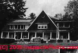
In the summer of 1981, mechanical engineer and air-quality researcher William Turner bought a heat-leaking house 40 miles northwest of Portland, Maine. Built in 1926 as a summer home for a Broadway playwright, the 3600-square foot wood-frame house had never been insulated. The builder's effort went instead into grand design and distinctive finishes: most rooms sport floor-to-ceiling wainscoting and tongue-and-groove wooden ceilings.
Adding Super-Insulation to a 1926 Home
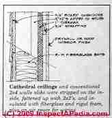
To make the house heatable for the first winter, Turner started on the inside. He tore down the wooden cladding on walls and ceilings and added heavy insulation. With a crew of three, he added 2x2's to the studs, and stuffed the wall cavities with 6-inch fiberglass insulation batts.
Next, the crew rolled poly out on the walls - lapping it one full stud at seams - and installed an inch of Thermax rigid insulation, horizontal strapping 16 inches on-center, and 1/2-inch drywall. They ran the wiring in the 3/4-inch strapping space.
All the walls got this R-26 superinsulation system, except a few spots where bookshelves and built-ins were in the way. These areas were blown with cellulose insulation and caulked on the interior.
The house had a sweeping cathedral ceiling on the north side, and a full attic below the main roof. On the cathedral ceiling, the 2x6 rafters were deepened with 1x2s, then insulated with R-19 fiberglass insulating batts, leaving a small air channel above the insulation. In the attic, a 10-inch layer and a 6-inch layer of fiberglass batts were installed at right angles to one another.
Turner placed strips of aluminized building paper and poly between the joists, believing at the time that foil strips would serve as an adequate vapor barrier. "I got conflicting advice on whether to install a continuous ceiling vapor barrier or not. And I didn't want to enclose the ceiling joists in poly," said Turner. "A house has to breathe,"I was told at the time.
All floors got R-19 fiberglass insulation batts stapled to the joists - kraft paper facing down into a vented crawlspace. The crew punctured the kraft-paper backing to let any moisture escape, but the interior side of the cavity received no vapor barrier. At the time, Turner saw no practical way to create a vapor barrier on the warm side of the floor insulation, short of removing the hard-pine finish flooring. [DJF note: normally we place the vapor barrier on the warm side - that is, up towards the floor above over a crawl. There is a risk of forming a moisture trap between the joists if it faces down, even though installation is easier in that position.]
Of the house's 34 windows, a few were replaced with double glazing and storms. The rest got triple-track exterior storms and inexpensive sheet-vinyl glazing on the interior - a poor-man's triple-glazing window design. The family installed high-R window-insulation panels on subfreezing nights. They left some panels in all winter. "If I did it over," said Turner, I'd use triple glazing, maybe with night insulation in bedrooms and baths."
Heating Equipment Updates to Reduce Energy Costs
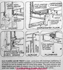
To house the new furnace and water heater they built a small 6-by-12 foot concrete block basement under the first floor bath, and wrapped it in 4 inches of beadboard. Four inches of beadboard was also added around the base of a large chimney where it protruded into the crawl space.
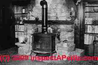
Heating during the first winter was divided roughly in half between the oil-fired furnace and an air-tight woodstove (left).
Watch out: be careful not to place combustible insulation against a chimney where sparks or heat could cause a fire, or where a chimney leak might be hidden: don't insulate over a chimney cleanout door, for example.
See HEATING COST SAVINGS METHODS for energy saving suggestions focused on the heating equipment itself.
Energy Saving Building Retrofits: Expectations vs. Reality
[Also see ENERGY SAVINGS RETROFIT LEAK SEALING GUIDE a sidebar to this article]: heating cost energy saving retrofit realities rarely match textbook diagrams. Pipes and wires get in your way, spaces are inaccessible, and the building details you discover often boggle the mind. And because textbook buildings rarely match real ones, real energy savings often fall short of predictions.
Surprising heating costs in a super-insulated building
The work completed, Turner moved in and fired up the oil-fired furnace and the woodstove, only to find that the house at up almost 20 MMBTU more fuel than expected - based on an estimated load of 4 BTU/ (ft2 degree day). That first winter, total energy use for heating, half wood and half oil, was about 13t MMBTU, rather than the 117 MMBTU estimated.
When Turner realized that the house's performance was not up to snuff, he called in a crew of house doctors to investigate. With a blower door and infrared scanner (thermography shows areas of heat loss), they quickly spotted massive air flows up through the slatted wood ceilings on the second floor. And this was on a relatively mild 35 degF. day.
The added air and heat infiltration losses, reasoned Turner, could easily account for the missing BTUs. Calculations revealed that in a house that size, an extra 0.2 air changes per hour (over the estimated 0.5 ACH) would make the difference. (See HEAT LOSS in BUILDINGS and HEAT LOSS DETECTION TOOLS and HEAT LOSS INDICATORS for details.)
Ice Dam Leaks in a Newly Insulated Building
Another problem Turner faced the first winter was a large ice dam on the sloping north roof that caused minor flooding in the wall. The retrofit team had yet to install soffit or ridge vent, so the 1-inch air space above the insulation was blocked off. That and two northeasters (storms) that dumped 3 feet of snow on the roof were to blame.
[DJF note: wall leaks from plumbing or ice dams not only end the effectiveness of insulation by making it wet, there is a risk of potentially significant mold damage and longer term, rot or insect damage. See ROOF ICE DAM LEAKS for details.]
Fixing Air & Heat Leak Losses in the Super-Insulated Home - Taking the Building Doctors' Advice
Adding a Top Floor AIr/Vapor Barrier
Having pinpointed the attic as a major source of air and heat leaks, Turner and crew went back and temporarily removed the 16 inches of attic insulation. They laid in a continuous poly air/vapor barrier in the ceiling (below the attic floor).
The new vapor barrier ran across the ceiling, going up and over each ceiling joist [a common retrofit approach], and all the joints in the vapor barrier were caulked and stapled. Then they reinstalled the insulation over the new vapor barrier. "It was a job I hope never to repeat." said Turner.
Stopping the ice dams
As for the ice dams, Turner chose not to install top and bottom vents, given the complexity of venting a shed roof. Instead he used heat tapes timed to run one hour a day -- they seem to work satisfactorily. (See HEAT TAPES & CABLES on Roofs for Ice Dams
for details.)
[DJF note: while this solution may prevent leaks by melting water escape channels through the ice dams, it won't prevent attic condensation, trapped moisture, or mold in the future. (See ROOF ICE DAM LEAKS for details.)
Suggestions for Sealing Air & Heat Leaks in the Insulated Building at Six Trouble Spots
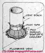
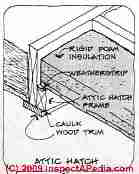
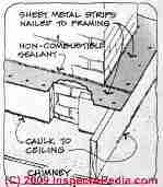
Our sketches shown here provide details of how a number of air and heat leaks were identified and sealed in the home. These sketches are enlargements taken from Energy Retrofit of an Older Building - part 2. In a typical leaky attic floor, common leak points are through chimney chases, plumbing vent stacks (above left), ceiling light fixtures, bath fans (below center), and partition wall tops.
The attic hatch was sealed using rigid foam insulation (above center), and metal flashing combined with fireproof caulk were used to seal around the chimney chase (above right).
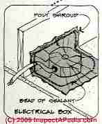
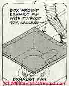
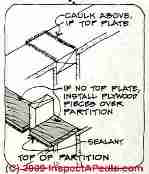
These sketches show additional air and heat loss sealing methods for ceiling electrical boxes (above right), the bath exhaust fan (above center), and the top of building partition walls (above right).
Sealing Air Leaks in Building Floors
The other major step the house doctors recommended was to seal air leaks in the floors. A cantilevered section of the second floor, which projects over the porch, was sealed with housewrap (Tyvek). The main floor, built over a vented crawl space, was not yet sealed. These details of the floor air and heat leak sealing procedures are described at ENERGY SAVINGS RETROFIT LEAK SEALING GUIDE and are shown in the sketch at left.
Said Turner, "On windy or very cold days, it's still uncomfortably drafty on the first floor - but there's no way to seal it." In some places the crawl space is just a foot height. Options that were being considered at that time included Tyvek, rigid foam insulation, and rigid fiberglass insulation.
[DJF Note: That comment was in the mid 1980's. Current (2009) best construction practices have shifted from venting crawl spaces to sealing the crawl space from outside, drying it out, and converting the crawl area to "conditioned space".
See CRAWL SPACE DRYOUT PROCEDURES and because we do not recommend use of fiberglass insulation in potentially wet or damp areas like hard-to-access crawl spaces, see CRAWLSPACE MOLD ADVICE.]
Evaluation of Energy Retrofit Savings: Results of Sealing Air Leaks
Although the house could not be thoroughly tightened, the next winter's energy consumption fell well below the original estimate - at around 90 MM BTU. "The major [heating cost] savings" said Turner, "may have resulted from sealing the building well on top." While the current performance doesn't hold a candle to the featherweight heating bills many superinsulators seek, it's quite respectable for a sprawling 3600-square foot antique in an 8500-degree-day climate.
Turner's future plans included a sunspace with 100 square feet of vertical south-facing glass, replacement windows for the hopelessly leaky French-style antiques, and a better air seal on the top floor. [DJF note: that top floor might have been better-sealed using a pumped-in insulating foam.] These improvements, plus Turner's continuing effort to caulk and seal against air leakage will result in further savings.
"Insulation alone will create a 'superinsulated' structure," said the weary but warm retrofitter, "but only meticulous attention to reducing air movement in and out of the structure will allow it to perform as an energy-efficient dwelling."
Links to the original article in PDF form immediately below are followed by an expanded/updated online version of this article.
- Energy Retrofit of an Older Building - PDF form, use your browser's back button to return to this page
- Energy Retrofit of an Older Building - part 2: PDF form, sketches of attic and basement air leak locations & their remedy
- Energy Retrofit of an Older Building - part 3: PDF form, sealing air leaks at old floors
- Energy Retrofit of an Older Building - part 4: PDF form, finding and sealing attic air leaks
Here we include solar energy, solar heating, solar hot water, and related building energy efficiency improvement articles reprinted/adapted/excerpted with permission from Solar Age Magazine - editor Steven Bliss.
Old House Energy Savings Research
- Energy Savers: Whole House Systems Approach to Energy Efficient Home Design [copy on file as /interiors/Whole_House_Energy_Efficiency_DOE.pdf ] - U.S. Department of Energy
- Brick nogging used as soundproofing was mentioned in a now-no-longer-online article on Popular Forest Magazine poplarforest.org
- The National Institute of Standards and Technology, NIST (nee National Bureau of Standards NBS) is a US government agency - see www.nist.gov
- "A Parametric Study of Wall Moisture Contents Using a Revised Variable Indoor Relative Humidity Version of the "Moist" Transient Heat and Moisture Transfer Model [copy on file as/interiors/MOIST_Model_NIST_b95074.pdf ] - ", George Tsongas, Doug Burch, Carolyn Roos, Malcom Cunningham; this paper describes software and the prediction of wall moisture contents. - PDF Document from NIS
...
HEAT LOSS DETECTION TOOLS or select a topic from the closely-related articles below, or see the complete ARTICLE INDEX.
Or see these
Recommended Articles
- AIR LEAK DETECTION TOOLS
- AIR LEAK MINIMIZATION
- AIR SEALING STRATEGIES
- ENERGY SAVINGS in BUILDINGS - home
- HEATING COST SAVINGS METHODS
- HOUSE DOCTOR, how-to be
- INSULATION INSPECTION & IMPROVEMENT
- SUPERINSULATION RETROFIT
- WINDOW / DOOR ENERGY EFFICIENT, DOE
Suggested citation for this web page
ENERGY SAVINGS RETROFIT CASE STUDY at InspectApedia.com - online encyclopedia of building & environmental inspection, testing, diagnosis, repair, & problem prevention advice.
Or see this
INDEX to RELATED ARTICLES: ARTICLE INDEX to BUILDING ENERGY SAVINGS
Or use the SEARCH BOX found below to Ask a Question or Search InspectApedia
Ask a Question or Search InspectApedia
Try the search box just below, or if you prefer, post a question or comment in the Comments box below and we will respond promptly.
Search the InspectApedia website
Note: appearance of your Comment below may be delayed: if your comment contains an image, photograph, web link, or text that looks to the software as if it might be a web link, your posting will appear after it has been approved by a moderator. Apologies for the delay.
Only one image can be added per comment but you can post as many comments, and therefore images, as you like.
You will not receive a notification when a response to your question has been posted.
Please bookmark this page to make it easy for you to check back for our response.
IF above you see "Comment Form is loading comments..." then COMMENT BOX - countable.ca / bawkbox.com IS NOT WORKING.
In any case you are welcome to send an email directly to us at InspectApedia.com at editor@inspectApedia.com
We'll reply to you directly. Please help us help you by noting, in your email, the URL of the InspectApedia page where you wanted to comment.
Citations & References
In addition to any citations in the article above, a full list is available on request.
- Solar Age Magazine was the official publication of the American Solar Energy Society. The contemporary solar energy magazine associated with the Society is Solar Today. "Established in 1954, the nonprofit American Solar Energy Society (ASES) is the nation's leading association of solar professionals & advocates. Our mission is to inspire an era of energy innovation and speed the transition to a sustainable energy economy. We advance education, research and policy. Leading for more than 50 years. ASES leads national efforts to increase the use of solar energy, energy efficiency and other sustainable technologies in the U.S. We publish the award-winning SOLAR TODAY magazine, organize and present the ASES National Solar Conference and lead the ASES National Solar Tour – the largest grassroots solar event in the world."
- Steve Bliss's Building Advisor at buildingadvisor.com helps homeowners & contractors plan & complete successful building & remodeling projects: buying land, site work, building design, cost estimating, materials & components, & project management through complete construction. Email: info@buildingadvisor.com
Steven Bliss served as editorial director and co-publisher of The Journal of Light Construction for 16 years and previously as building technology editor for Progressive Builder and Solar Age magazines. He worked in the building trades as a carpenter and design/build contractor for more than ten years and holds a masters degree from the Harvard Graduate School of Education. Excerpts from his recent book, Best Practices Guide to Residential Construction, Wiley (November 18, 2005) ISBN-10: 0471648361, ISBN-13: 978-0471648369, appear throughout this website, with permission and courtesy of Wiley & Sons. Best Practices Guide is available from the publisher, J. Wiley & Sons, and also at Amazon.com - Best Practices Guide to Residential Construction, by Steven Bliss. John Wiley & Sons, 2006. ISBN-10: 0471648361, ISBN-13: 978-0471648369, Hardcover: 320 pages, available from Amazon.com and also Wiley.com. See our book review of this publication.
- In addition to citations & references found in this article, see the research citations given at the end of the related articles found at our suggested
CONTINUE READING or RECOMMENDED ARTICLES.
- Carson, Dunlop & Associates Ltd., 120 Carlton Street Suite 407, Toronto ON M5A 4K2. Tel: (416) 964-9415 1-800-268-7070 Email: info@carsondunlop.com. Alan Carson is a past president of ASHI, the American Society of Home Inspectors.
Thanks to Alan Carson and Bob Dunlop, for permission for InspectAPedia to use text excerpts from The HOME REFERENCE BOOK - the Encyclopedia of Homes and to use illustrations from The ILLUSTRATED HOME .
Carson Dunlop Associates provides extensive home inspection education and report writing material. In gratitude we provide links to tsome Carson Dunlop Associates products and services.


